E110 FIREYE FLAME-MONITOR™ - Westmill Industries
E110 FIREYE FLAME-MONITOR™ - Westmill Industries
E110 FIREYE FLAME-MONITOR™ - Westmill Industries

You also want an ePaper? Increase the reach of your titles
YUMPU automatically turns print PDFs into web optimized ePapers that Google loves.
26<br />
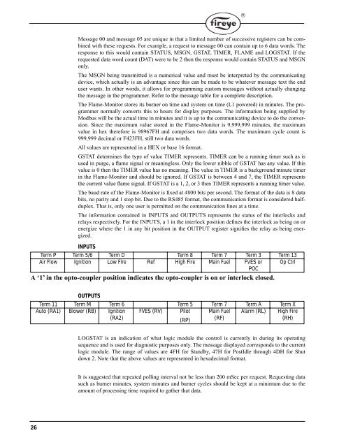
Message 00 and message 05 are unique in that a limited number of successive registers can be combined<br />
with these requests. For example, a request to message 00 can contain up to 6 data words. The<br />
response to this would contain STATUS, MSGN, GSTAT, TIMER, <strong>FLAME</strong> and LOGSTAT. If the<br />
requested data word count (DAT) were to be 2 then the response would contain STATUS and MSGN<br />
only.<br />
The MSGN being transmitted is a numerical value and must be interpreted by the communicating<br />
device, which actually is an advantage since this can be made to be whatever message text the end<br />
user wants. In other words, it allows for programming custom messages without actually changing<br />
the message in the programmer. Refer to the message table for a complete description.<br />
The Flame-Monitor stores its burner on time and system on time (L1 powered) in minutes. The programmer<br />
normally converts this to hours for display purposes. The information being supplied by<br />
Modbus will be the actual time in minutes and it is up to the communicating device to do the conversion.<br />
Since the maximum value stored in the Flame-Monitor is 9,999,999 minutes, the maximum<br />
value in hex therefore is 98967FH and comprises two data words. The maximum cycle count is<br />
999,999 decimal or F423FH, still two data words.<br />
All values are represented in a HEX or base 16 format.<br />
GSTAT determines the type of value TIMER represents. TIMER can be a running timer such as is<br />
used in purge, a flame signal or meaningless. Only the lower nibble of GSTAT has any value. If this<br />
value is 0 then the TIMER value has no meaning. The value in TIMER is a background minute timer<br />
in the Flame-Monitor and should be ignored. If GSTAT is between 4 and 7, the TIMER represents<br />
the current value flame signal. If GSTAT is a 1, 2, or 3 then TIMER represents a running timer value.<br />
The baud rate of the Flame-Monitor is fixed at 4800 bits per second. The format of the data is 8 data<br />
bits, no parity and 1 stop bit. Due to the RS485 format, the communication format is considered halfduplex.<br />
That is, only one user is permitted on the communication lines at a time.<br />
The information contained in INPUTS and OUTPUTS represents the status of the interlocks and<br />
relays respectively. For the INPUTS, a 1 in the interlock position defines the interlock as being on or<br />
energize where the 1 in any bit position in the OUTPUT register signifies the relay as being energized.<br />
Term P<br />
INPUTS<br />
Term 5/6 Term D Term 8 Term 7 Term 3 Term 13<br />
Air Flow Ignition Low Fire Ref High Fire Main Fuel FVES or<br />
POC<br />
Op Ctrl<br />
A ‘1’ in the opto-coupler position indicates the opto-coupler is on or interlock closed.<br />
OUTPUTS<br />
Term 11 Term M Term 6 Term 5 Term 7 Term A Term X<br />
Auto (RA1) Blower (RB) Ignition FVES (RV) Pilot Main Fuel Alarm (RL) High Fire<br />
(RA2)<br />
(RP) (RF)<br />
(RH)<br />
LOGSTAT is an indication of what logic module the control is currently in during its operating<br />
sequence and is used for diagnostic purposes only. The message displayed corresponds to the current<br />
logic module. The range of values are 4FH for Standby, 47H for PostIdle through 4DH for Shut<br />
down 2. Note that the above values are represented in hexadecimal format.<br />
It is suggested that repeated polling interval not be less than 200 mSec per request. Requesting data<br />
such as burner minutes, system minutes and burner cycles should be kept at a minimum due to the<br />
amount of processing time required to gather that data.<br />
®