E110 FIREYE FLAME-MONITOR™ - Westmill Industries
E110 FIREYE FLAME-MONITOR™ - Westmill Industries
E110 FIREYE FLAME-MONITOR™ - Westmill Industries

Create successful ePaper yourself
Turn your PDF publications into a flip-book with our unique Google optimized e-Paper software.
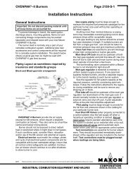
14<br />
4. Purge Interlock: Generally a firing rate motor linkage position switch or a differential air-pressure<br />
switch, that proves a maximum purge air flow rate. It is connected between Terminals D and<br />
8. The purge interlock proves that the purge air flow rate is at maximum during the purge.<br />
5. Running Interlocks: These generally are air flow switches, high and low fuel pressure switches,<br />
oil temperature switches, atomizing media pressure switches, and excess smoke density controls.<br />
These interlocks prove proper conditions for normal operation of the burner. They are wired in<br />
series and connected between Terminals 3 and P.<br />
6. Low Fire Start Interlock: Generally a firing rate motor linkage position switch or a damper<br />
position switch, will prove both the linkage and dampers are in their proper positions to begin<br />
burner light off. This switch is connected between Terminals M and D.<br />
®