E110 FIREYE FLAME-MONITOR™ - Westmill Industries
E110 FIREYE FLAME-MONITOR™ - Westmill Industries
E110 FIREYE FLAME-MONITOR™ - Westmill Industries

Create successful ePaper yourself
Turn your PDF publications into a flip-book with our unique Google optimized e-Paper software.
INSTALLING THE CONTROL<br />
OPERATION<br />
10<br />
3. Reconnect the neutral wire (L2) at the power source. Remove the test probe from the grounded<br />
terminal and reconnect it to Terminal L2 in the wiring base. With the other probe, touch each<br />
other terminal. It is normal to obtain a resistance reading on the meter at some terminals during<br />
this test as there are resistive loads (coils, transformers, lamps, etc.) connected whose normal<br />
DC resistance may be less than 5 ohms. However, at no time should the test meter read zero<br />
ohms.<br />
CAUTION: Restore power for the following test.<br />
4. With Flame-Monitor removed, measure voltage from L2 to all other terminals. Reading should<br />
be zero on all terminals except Ll.<br />
CAUTION: Electric power must be turned off during installation.<br />
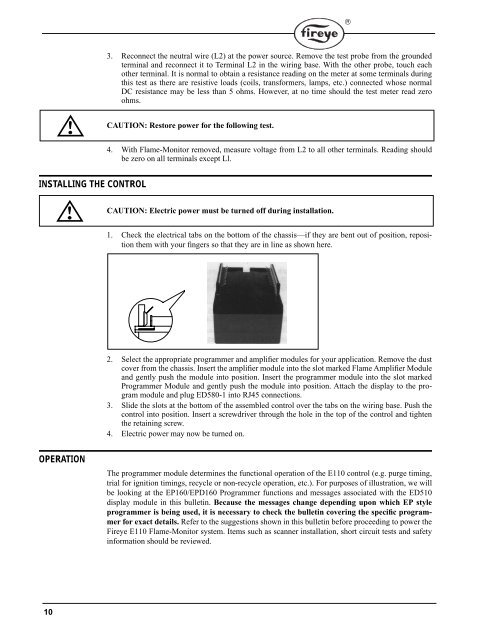
1. Check the electrical tabs on the bottom of the chassis—if they are bent out of position, reposition<br />
them with your fingers so that they are in line as shown here.<br />
2. Select the appropriate programmer and amplifier modules for your application. Remove the dust<br />
cover from the chassis. Insert the amplifier module into the slot marked Flame Amplifier Module<br />
and gently push the module into position. Insert the programmer module into the slot marked<br />
Programmer Module and gently push the module into position. Attach the display to the program<br />
module and plug ED580-1 into RJ45 connections.<br />
3. Slide the slots at the bottom of the assembled control over the tabs on the wiring base. Push the<br />
control into position. Insert a screwdriver through the hole in the top of the control and tighten<br />
the retaining screw.<br />
4. Electric power may now be turned on.<br />
The programmer module determines the functional operation of the <strong>E110</strong> control (e.g. purge timing,<br />
trial for ignition timings, recycle or non-recycle operation, etc.). For purposes of illustration, we will<br />
be looking at the EP160/EPD160 Programmer functions and messages associated with the ED510<br />
display module in this bulletin. Because the messages change depending upon which EP style<br />
programmer is being used, it is necessary to check the bulletin covering the specific programmer<br />
for exact details. Refer to the suggestions shown in this bulletin before proceeding to power the<br />
Fireye <strong>E110</strong> Flame-Monitor system. Items such as scanner installation, short circuit tests and safety<br />
information should be reviewed.<br />
®