E110 FIREYE FLAME-MONITOR™ - Westmill Industries
E110 FIREYE FLAME-MONITOR™ - Westmill Industries
E110 FIREYE FLAME-MONITOR™ - Westmill Industries
Create successful ePaper yourself
Turn your PDF publications into a flip-book with our unique Google optimized e-Paper software.
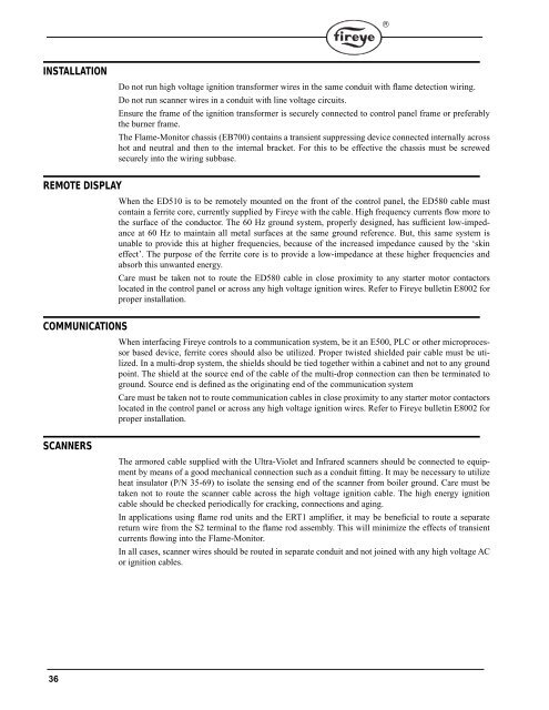
INSTALLATION<br />
36<br />
Do not run high voltage ignition transformer wires in the same conduit with flame detection wiring.<br />
Do not run scanner wires in a conduit with line voltage circuits.<br />
Ensure the frame of the ignition transformer is securely connected to control panel frame or preferably<br />
the burner frame.<br />
The Flame-Monitor chassis (EB700) contains a transient suppressing device connected internally across<br />
hot and neutral and then to the internal bracket. For this to be effective the chassis must be screwed<br />
securely into the wiring subbase.<br />
REMOTE DISPLAY<br />
When the ED510 is to be remotely mounted on the front of the control panel, the ED580 cable must<br />
contain a ferrite core, currently supplied by Fireye with the cable. High frequency currents flow more to<br />
the surface of the conductor. The 60 Hz ground system, properly designed, has sufficient low-impedance<br />
at 60 Hz to maintain all metal surfaces at the same ground reference. But, this same system is<br />
unable to provide this at higher frequencies, because of the increased impedance caused by the ‘skin<br />
effect’. The purpose of the ferrite core is to provide a low-impedance at these higher frequencies and<br />
absorb this unwanted energy.<br />
Care must be taken not to route the ED580 cable in close proximity to any starter motor contactors<br />
located in the control panel or across any high voltage ignition wires. Refer to Fireye bulletin E8002 for<br />
proper installation.<br />
COMMUNICATIONS<br />
When interfacing Fireye controls to a communication system, be it an E500, PLC or other microprocessor<br />
based device, ferrite cores should also be utilized. Proper twisted shielded pair cable must be utilized.<br />
In a multi-drop system, the shields should be tied together within a cabinet and not to any ground<br />
point. The shield at the source end of the cable of the multi-drop connection can then be terminated to<br />
ground. Source end is defined as the originating end of the communication system<br />
Care must be taken not to route communication cables in close proximity to any starter motor contactors<br />
located in the control panel or across any high voltage ignition wires. Refer to Fireye bulletin E8002 for<br />
proper installation.<br />
SCANNERS<br />
The armored cable supplied with the Ultra-Violet and Infrared scanners should be connected to equipment<br />
by means of a good mechanical connection such as a conduit fitting. It may be necessary to utilize<br />
heat insulator (P/N 35-69) to isolate the sensing end of the scanner from boiler ground. Care must be<br />
taken not to route the scanner cable across the high voltage ignition cable. The high energy ignition<br />
cable should be checked periodically for cracking, connections and aging.<br />
In applications using flame rod units and the ERT1 amplifier, it may be beneficial to route a separate<br />
return wire from the S2 terminal to the flame rod assembly. This will minimize the effects of transient<br />
currents flowing into the Flame-Monitor.<br />
In all cases, scanner wires should be routed in separate conduit and not joined with any high voltage AC<br />
or ignition cables.<br />
®


