Conveyor chain
Conveyor chain
Conveyor chain

Create successful ePaper yourself
Turn your PDF publications into a flip-book with our unique Google optimized e-Paper software.
Designer Guide<br />
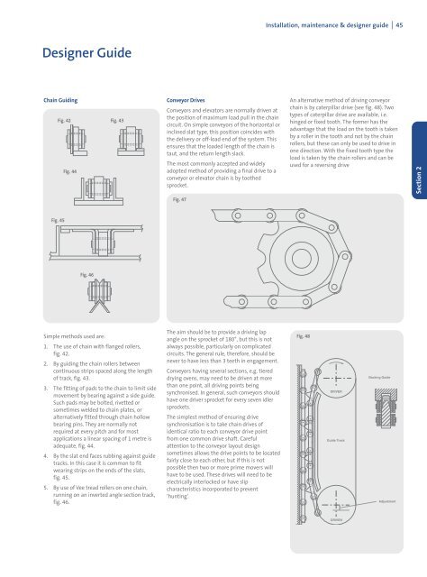
Chain Guiding<br />
Fig. 42 Fig. 43<br />
Fig. 45<br />
Fig. 44<br />
Fig. 46<br />
Simple methods used are:<br />
1. The use of <strong>chain</strong> with flanged rollers,<br />
fig. 42.<br />
2. By guiding the <strong>chain</strong> rollers between<br />
continuous strips spaced along the length<br />
of track, fig. 43.<br />
3. The fitting of pads to the <strong>chain</strong> to limit side<br />
movement by bearing against a side guide.<br />
Such pads may be bolted, rivetted or<br />
sometimes welded to <strong>chain</strong> plates, or<br />
alternatively fitted through <strong>chain</strong> hollow<br />
bearing pins. They are normally not<br />
required at every pitch and for most<br />
applications a linear spacing of 1 metre is<br />
adequate, fig. 44.<br />
4. By the slat end faces rubbing against guide<br />
tracks. In this case it is common to fit<br />
wearing strips on the ends of the slats,<br />
fig. 45.<br />
5. By use of Vee tread rollers on one <strong>chain</strong>,<br />
running on an inverted angle section track,<br />
fig. 46.<br />
<strong>Conveyor</strong> Drives<br />
<strong>Conveyor</strong>s and elevators are normally driven at<br />
the position of maximum load pull in the <strong>chain</strong><br />
circuit. On simple conveyors of the horizontal or<br />
inclined slat type, this position coincides with<br />
the delivery or off-load end of the system. This<br />
ensures that the loaded length of the <strong>chain</strong> is<br />
taut, and the return length slack.<br />
The most commonly accepted and widely<br />
adopted method of providing a final drive to a<br />
conveyor or elevator <strong>chain</strong> is by toothed<br />
sprocket.<br />
Fig. 47<br />
The aim should be to provide a driving lap<br />
angle on the sprocket of 180°, but this is not<br />
always possible, particularly on complicated<br />
circuits. The general rule, therefore, should be<br />
never to have less than 3 teeth in engagement.<br />
<strong>Conveyor</strong>s having several sections, e.g. tiered<br />
drying ovens, may need to be driven at more<br />
than one point, all driving points being<br />
synchronised. In general, such conveyors should<br />
have one driver sprocket for every seven idler<br />
sprockets.<br />
The simplest method of ensuring drive<br />
synchronisation is to take <strong>chain</strong> drives of<br />
identical ratio to each conveyor drive point<br />
from one common drive shaft. Careful<br />
attention to the conveyor layout design<br />
sometimes allows the drive points to be located<br />
fairly close to each other, but if this is not<br />
possible then two or more prime movers will<br />
have to be used. These drives will need to be<br />
electrically interlocked or have slip<br />
characteristics incorporated to prevent<br />
‘hunting’.<br />
Installation, maintenance & designer guide I 45<br />
An alternative method of driving conveyor<br />
<strong>chain</strong> is by caterpillar drive (see fig. 48). Two<br />
types of caterpillar drive are available, i.e.<br />
hinged or fixed tooth. The former has the<br />
advantage that the load on the tooth is taken<br />
by a roller in the tooth and not by the <strong>chain</strong><br />
rollers, but these can only be used to drive in<br />
one direction. With the fixed tooth type the<br />
load is taken by the <strong>chain</strong> rollers and can be<br />
used for a reversing drive<br />
Fig. 48<br />
DRIVER<br />
Guide Track<br />
DRIVEN<br />
Backing Guide<br />
Adjustment<br />
Section 2