Through-Wall Imaging Radar - MIT Lincoln Laboratory
Through-Wall Imaging Radar - MIT Lincoln Laboratory
Through-Wall Imaging Radar - MIT Lincoln Laboratory

Create successful ePaper yourself
Turn your PDF publications into a flip-book with our unique Google optimized e-Paper software.
every 1.9 seconds [1, 2]. The imaging algorithm is a realtime<br />
implementation of the range migration algorithm<br />
(RMA) synthetic aperture radar (SAR) imaging algorithm<br />
based on work from a high-speed imaging architecture<br />
originally developed for real-time interferometric synthetic<br />
aperture microscopy [3].<br />
For the system shown in this article, the maximum<br />
range when imaging through a 20 cm thick, solid concrete<br />
wall is estimated to be 20 m. Free-space measurements<br />
will show that this system is capable of resolving rapidly<br />
moving human targets and low radar-cross-section (RCS)<br />
targets. <strong>Through</strong>-wall measurements will show that this<br />
system is capable of locating human targets that are either<br />
moving or standing still behind 10 cm and 20 cm thick,<br />
solid concrete walls and through cinder-block walls at a<br />
standoff range approximately 6 m from the wall and 10 m<br />
from the targets. Preliminary detection work demonstrates<br />
the feasibility of plotting detections and providing a head<br />
count in real time rather than displaying raw SAR imagery.<br />
Future work will include testing on an adobe structure and<br />
actual random buildings with diverse target scenes.<br />
system description<br />
The radar system can be described in four parts: the hardware,<br />
the antenna array, the imaging algorithm, and the<br />
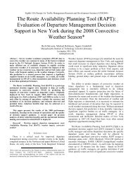
data acquisition and graphical user interface (GUI). Photographs<br />
of the radar system are shown in Figure 2.<br />
<strong>Radar</strong> System<br />
The core of this system is a range-gated FMCW radar<br />
device that transmits linear frequency-modulated (LFM)<br />
chirps from 2–4 GHz in 1 ms with 1 W peak transmit<br />
John E. PEabody, Jr., GrEGory L. CharvaT, JusTin Goodwin, and MarTin Tobias<br />
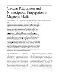
FiGurE 1. The through-wall radar sensor would be<br />
mounted on a vehicle and would operate at standoff ranges,<br />
providing range and cross-range position of moving targets<br />
within an urban structure.<br />
power at 50% duty cycle. Figure 3 shows the transmit<br />
and receive ports are fed to fan-out switch matrices con-<br />
nected to the array elements. This radar architecture<br />
implements a range gate by using a high-Q intermediatefrequency<br />
(IF) filter FL1 [4]. This filter band-limits the<br />
decorrelated LFM prior to pulse compression, resulting<br />
in an effective range gate of the target by rejecting scattered<br />
returns from the air-wall boundary, thereby providing<br />
a spatial frequency range gate. This design provides<br />
maximum dynamic range and sensitivity for imaging<br />
targets behind a wall [5, 6].<br />
Antenna Array<br />
The antenna array is shown in Figure 2a. The transmit<br />
port of the FMCW radar is connected to a fan-out<br />
switch matrix made up of switches SW1–3 (shown in Fig-<br />
(a) (b)<br />
FiGurE 2. Photographs of the through-wall radar imaging system show (a) the antenna elements on the front of the system,<br />
and (b) the transmitter, receiver, power supplies, diagnostic oscilloscope, and computer on the back.<br />
VOLUME 19, NUMBER 1, 2012 n LINCOLN LABORATORY JOURNAL 63