Through-Wall Imaging Radar - MIT Lincoln Laboratory
Through-Wall Imaging Radar - MIT Lincoln Laboratory
Through-Wall Imaging Radar - MIT Lincoln Laboratory

You also want an ePaper? Increase the reach of your titles
YUMPU automatically turns print PDFs into web optimized ePapers that Google loves.
5.75<br />
5.75<br />
8<br />
All antenna switches (SW1–4) are solid state and dig-<br />
itally controlled by the data-acquisition computer. The<br />
TDM MIMO radar system sequences through each of<br />
the 44 bistatic combinations, acquiring one range profile<br />
at each. The computer controls the switches, pulses the<br />
transmitter, and digitizes the video; executes these tasks<br />
in a continuous loop; and simultaneously computes and<br />
displays a SAR image at a rate of 10.8 Hz.<br />
<strong>Imaging</strong> Algorithm<br />
This radar resolves targets by using the RMA, which is a<br />
near-field SAR imaging algorithm [7]. Processing a single<br />
image with the RMA is computationally expensive. A<br />
careful implementation of the RMA was developed so that<br />
values are precomputed and preorganized in the memory<br />
whenever possible. A real-time beamforming algorithm in<br />
Data acquisition system<br />
GUI<br />
Data<br />
display<br />
System<br />
control<br />
External routing<br />
Internal routing<br />
John E. PEabody, Jr., GrEGory L. CharvaT, JusTin Goodwin, and MarTin Tobias<br />
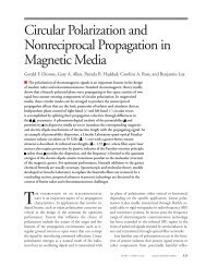
12 4 20 4 20 4 20 4 8 Receive elements<br />
2<br />
Data<br />
processing<br />
algorithms<br />
Analog<br />
output<br />
86<br />
96<br />
a C++ class was designed to execute a high-speed, hardware-optimized<br />
RMA. A MATLAB executable (MEX)<br />
interface was designed to prototype the algorithm in a<br />
debug environment. This interface allows for continued<br />
development of processing routines. The combination of<br />
these streamlined processes provides real-time imaging<br />
at a rate of 10.8 Hz [5].<br />
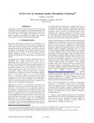
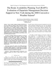
Data Acquisition and Graphical User Interface<br />
The data-acquisition (DAQ) system acquires data from<br />
the radar and provides system control through a GUI that<br />
displays the processed data and establishes a pipeline to<br />
and from the data processing algorithms to facilitate realtime<br />
radar imaging frame rates. A block diagram of the<br />
DAQ system is shown in Figure 6. A screen shot of the<br />
GUI is shown in Figure 7 [5].<br />
Data ring buffers<br />
Analog input<br />
Sample clock<br />
generator<br />
Recorded data<br />
storage<br />
Digital<br />
outputs<br />
44 Evenly spaced<br />
phase centers<br />
13 Evenly spaced<br />
transmit elements<br />
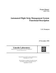
FiGurE 5. In this cartoon of the time-division multiplexed (TDM), multiple-input, multiple-output (MIMO) array layout<br />
[compare to Figure 2(a)](units in inches), large circles represent the antenna elements. The lines between the elements<br />
show the bistatic baselines, and the smaller circles indicate the location of each phase center. With this array,<br />
44 virtual elements can be synthesized with just 21 actual antenna elements.<br />
Input from<br />
video amplifier<br />
Output digital<br />
control to SW1–4<br />
Output to ramp<br />
generator<br />
FiGurE 6. The data acquisition (DAQ) system facilitates real-time imaging by using a high-speed data pipeline<br />
and real-time implementation of a synthetic aperture radar (SAR) imaging algorithm.<br />
VOLUME 19, NUMBER 1, 2012 n LINCOLN LABORATORY JOURNAL 65