EARTHQUAKE SAFETY EVALUATION OF ATATURK DAM
EARTHQUAKE SAFETY EVALUATION OF ATATURK DAM
EARTHQUAKE SAFETY EVALUATION OF ATATURK DAM

Create successful ePaper yourself
Turn your PDF publications into a flip-book with our unique Google optimized e-Paper software.
1 st National Symposium and<br />
Exposition on Dam Safety<br />
May 28-30, 2007<br />
<strong>EARTHQUAKE</strong> <strong>SAFETY</strong> <strong>EVALUATION</strong> <strong>OF</strong> <strong>ATATURK</strong> <strong>DAM</strong><br />
Martin WIELAND 1 , Sujan MALLA 2<br />
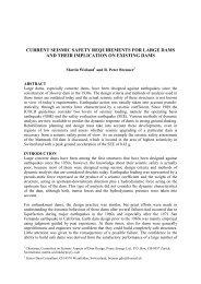
ABSTRACT<br />
The key structure for the development of the Lower Euphrates region is the Ataturk Dam, a<br />
multipurpose dam for hydropower generation, irrigation as well as domestic and industrial water<br />
supply. The 170 m high rockfill dam was designed against earthquakes using design criteria and<br />
methods of analysis that were valid at the time of the design. The construction of the dam was<br />
completed in 1990. A new guideline document on seismic design criteria for large dams was issued by<br />
ICOLD in 1989. As a consequence, the previously used seismic design criteria became obsolete.<br />
Hence, a re-assessment of the earthquake behaviour and safety of the dam was performed for the<br />
maximum credible earthquake (MCE). Based on new detailed information on the seismic hazard in<br />
Turkey, the MCE shaking at the dam site is estimated to have a peak horizontal ground acceleration of<br />
0.5 g. The dam is expected to undergo inelastic deformations during the MCE. The seismic safety<br />
evaluation included the following steps:<br />
• Specification of the ground motion of the MCE.<br />
• Evaluation of the effective static stresses in the dam due to dead and water loads.<br />
• Estimation of strain-dependent material properties for dynamic analysis.<br />
• Dynamic analysis of dam by equivalent linear method using a two-dimensional finite element<br />
model of the maximum section of the dam.<br />
• Analysis of seismic movements of potential sliding masses on the upstream and downstream slopes<br />
of the dam.<br />
• Analysis of permanent inelastic deformations of the dam due to the earthquake shaking.<br />
• Safety evaluation of the dam based on the estimated dam deformations.<br />
Because of the relatively flat slopes, the wide filter zones, and the thick clay core with self-healing<br />
properties, the dam is expected to perform well under the MCE ground motion.<br />
Keywords: Rockfill dam, equivalent linear earthquake analysis, seismic slope stability, dam safety<br />
assessment<br />
INTRODUCTION<br />
The most important results of the earthquake analysis of the Ataturk Dam subjected to the ground<br />
shaking produced by the maximum credible earthquake (MCE) are presented in this paper. The<br />
dynamic analysis of the dam subjected to the earthquake ground shaking was carried out with the help<br />
of a finite element model. Based on the results of this analysis, the dynamic stability and the<br />
earthquake-induced deformations of the dam were examined.<br />
1<br />
Chairman, ICOLD Committee on Seismic Aspects of Dam Design, Poyry Energy Ltd.,<br />
Hardturmstrasse 161, CH-8037 Zurich, Switzerland, e-mail: martin.wieland@poyry.com<br />
2<br />
Senior Engineer, Poyry Energy Ltd., Hardturmstrasse 161, CH-8037 Zurich, Switzerland, e-mail:<br />
sujan.malla@poyry.com
The earthquake analysis of the dam consisted of the following steps:<br />
1. Generation of input ground motion (in the form of artificial spectrum-compatible accelerograms)<br />
corresponding to the MCE, which was selected on the basis of the available information about the<br />
seismic hazard at the dam site<br />
2. Assessment of the following dynamic properties of each dam material<br />
• Maximum dynamic shear modulus (i.e. shear modulus for very small dynamic shear strains),<br />
which depends mainly on the mean effective static stresses and the relative density in the<br />
shells, and on the undrained shear strength in the clay core<br />
• Strain-dependence of dynamic shear modulus and damping ratio<br />
• Shear strength properties: angle of internal friction and cohesion<br />
• Other properties: Poisson’s ratio and mass density<br />
3. Dynamic analysis of the dam subjected to the earthquake ground motion by means of a finite<br />
element model using the equivalent linear method first developed by H.B. Seed and co-workers;<br />
this method is the state-of-the-practice in the earthquake analysis and design of embankment dams<br />
(several cases were analyzed in view of the random nature of the earthquake shaking and<br />
uncertainties concerning the dynamic material properties; the main result of interest from the<br />
dynamic analysis is the distribution of the earthquake accelerations in the dam, in particular, in<br />
potential sliding blocks)<br />
4. Selection of potential sliding surfaces and calculation of yield accelerations by performing slope<br />
stability calculations (note: the yield acceleration of a potential sliding mass is the pseudo-static<br />
horizontal earthquake acceleration for which the factor of safety against a sliding failure is equal<br />
to 1.0)<br />
5. Calculation of the permanent earthquake-induced displacements of the potential sliding masses<br />
based on the knowledge of their yield accelerations and the distribution of the earthquake<br />
accelerations (Newmark sliding block analysis)<br />
6. Seismic settlement analysis to determine the effect of vibration-induced densification of the dam<br />
materials during the earthquake shaking<br />
7. Determination of total loss of freeboard due to the sliding displacements caused by the dynamic<br />
slope instabilities as well as the seismic settlements<br />
8. Assessment of effect of the earthquake-induced deformations on safety against internal erosion in<br />
the dam.<br />
MAIN FEATURES <strong>OF</strong> <strong>ATATURK</strong> <strong>DAM</strong><br />
The Ataturk Dam is a zoned rockfill dam with a central core and is located on the Euphrates River.<br />
The main features of the dam are as follows:<br />
• Dam height: 170 m<br />
• Crest length: 1670 m<br />
• Crest level: 549 m<br />
• Maximum base width: approx. 900 m<br />
• Dam volume: 84 × 10 6 m 3<br />
• Reservoir volume: 48 km 3<br />
• Installed capacity: 2400 MW<br />
• Annual energy generation: 8100 GWh<br />
The construction of the cofferdam lasted from 1985 to 1987. The fill work for the main dam began in<br />
1987 and was completed in 1990. The reservoir level reached 535 m a.s.l. in March 1994 and has<br />
varied between 526 m and 537 m a.s.l. since then. The maximum and minimum operation reservoir<br />
levels are 542 m and 526 m a.s.l., respectively.
DESIGN <strong>EARTHQUAKE</strong> GROUND MOTION<br />
The Ataturk Dam is situated about 50 km southeast of the East Anatolian fault. The most recent<br />
damaging seismic activity associated with the East Anatolian fault took place on 27 June 1998 during<br />
the Adana-Ceyhan earthquake, which had a surface wave magnitude of 6.2 and an epicentral distance<br />
of about 270 km from the Ataturk dam site.<br />
To estimate the peak ground acceleration (PGA) of MCE at the dam site, the seismic hazard data from<br />
the Disaster Management Implementation and Research Centre of the Middle East Technical<br />
University (METU/DMC, 1999) were used as a basis. Accordingly, the peak horizontal ground<br />
accelerations at the dam site (rock surface) for various return periods are as follows:<br />
Return period (years) 100 225 475 1000<br />
Peak ground acceleration 0.22 g 0.27 g 0.33 g 0.39 g<br />
The maximum credible earthquake (MCE) is defined as the largest possible earthquake that can be<br />
reasonably expected to occur in the given tectonic setting. The return period of the MCE may be<br />
several thousand years. It is clear that the PGA of the MCE should be larger than that of an earthquake<br />
with a return period of 1000 years. In view of the above-mentioned information about the seismic<br />
hazard at the dam site, the PGA of horizontal shaking at the free surface of the rock due to the MCE<br />
was taken as 0.50 g.<br />
The vertical earthquake acceleration was also considered in this study. The PGA of the vertical<br />
component of the input earthquake motion was assumed to be equal to 2/3 of the PGA of the<br />
horizontal component. The elastic response spectrum defined by in the Turkish code was used<br />
(Ministry of Public Works and Settlement, 1998).<br />
In view of the random nature of the ground motion, three independent sets of artificial accelerograms<br />
were employed in the dynamic analysis. These spectrum-compatible accelerograms were generated<br />
with the computer program SIMQKE (Gasparini and Vanmarcke, 1976). The strong ground motion<br />
(i.e. the stationary part of the input motion) was assumed to last for 25 s, 30 s and 35 s for the three<br />
artificial earthquakes, respectively.<br />
TWO-DIMENSIONAL FINITE ELEMENT MODEL <strong>OF</strong> HIGHEST <strong>DAM</strong> SECTION<br />
A two-dimensional finite-element model of the dam was used for the dynamic analysis. Four-node<br />
plane-strain elements were employed. The two-dimensional model represents the central cross-section<br />
of the dam. The model geometry corresponds to the actual shape of the dam surface. The roads built<br />
on the dam surface were also modelled. Some adjustments made in the topmost part of the dam during<br />
the crest reinstatement were also incorporated. The horizontal and vertical degrees-of-freedom were<br />
fixed at the base of the dam, where the input seismic motion defined on the rock surface was applied.<br />
DYNAMIC MATERIAL PROPERTIES<br />
The behaviour of geotechnical materials subjected to an earthquake loading is highly nonlinear. In<br />
particular, the dynamic shear moduli and damping ratios of such materials are strongly influenced by<br />
the amplitudes of the dynamic shear strains. The dynamic characteristics of the dam materials had not<br />
been specially investigated by means of dynamic triaxial tests. Such tests would provide the necessary<br />
information about the dynamic properties of these materials. The material properties required for the<br />
dynamic analysis were obtained from the geotechnical literature on the dynamic characteristics of
comparable materials. Possible ranges of the most important dynamic properties were considered by<br />
analysing a number of cases.<br />
The Poisson’s ratios of the shells (including filters) and the core were assumed to be equal to 0.30 and<br />
0.47, respectively. The total mass densities of the dam materials corresponded to the total unit weights<br />
listed in Table 2.<br />
The principal features of the dynamic properties of the dam materials are explained below.<br />
Maximum dynamic shear modulus in upstream and downstream shells<br />
The maximum dynamic shear modulus Gmax of a cohesionless geotechnical material can be expressed<br />
as (Seed and Idriss, 1970)<br />
0.<br />
5<br />
G max = 220 k 2max ( σ′<br />
m ) (in kPa)<br />
where k2max is a material constant that depends primarily on the relative density and σ′ m is the mean<br />
effective static stress. Conventionally, the shear modulus for a cyclic shear strain amplitude of 10 -4 %<br />
is designated as Gmax, since the dynamic shear modulus is practically constant for strain amplitudes<br />
below this level.<br />
The possible range of values of k2max considered for the upstream and downstream shells was as<br />
follows (Seed et al., 1984):<br />
• Lower bound: k2max = 90<br />
• Average: k2max = 120<br />
• Upper bound: k2max = 150<br />
Maximum dynamic shear modulus in clay core<br />
The maximum dynamic shear modulus Gmax of the clay core depends primarily on the undrained shear<br />
strength su (Seed and Idriss, 1970). The approximate relationship between the two quantities can be<br />
expressed as<br />
⎧1200<br />
lower bound<br />
G max ⎪<br />
= ⎨2400<br />
average<br />
s u ⎪<br />
⎩3600<br />
upper bound<br />
The undrained shear strength su of the clay core varies from approximately 100 kPa at the top to<br />
220 kPa at the bottom of the dam. It is assumed to vary linearly over the dam height.<br />
Strain-dependence of dynamic shear modulus and damping ratio<br />
The dynamic shear modulus and the damping ratio of a fill material subjected to a cyclic loading vary<br />
substantially with the amplitude of the shear strain. In general, the shear modulus diminishes and the<br />
damping ratio grows when the dynamic shear strain amplitude becomes larger. The strain-dependence<br />
of the dam materials for the earthquake analysis is briefly discussed below.<br />
• Upstream and downstream shells: The dynamic shear modulus and the damping ratio of the<br />
upstream and downstream shells (including the filters) were assumed to vary with shear strain<br />
amplitude as shown in Fig. 1. These curves were proposed by Seed et al. (1984) based on a large<br />
number of cyclic triaxial tests made on gravelly soils, including the rockfill materials used in the<br />
Pyramid and Oroville Dams in USA.<br />
• Clay core: The strain-dependence of a clayey soil is strongly influenced by its plasticity index. The<br />
plasticity index of the core material of the Ataturk dam lies within the range of 20 to 45. The<br />
corresponding variation of the shear modulus and the damping ratio of the clay core with the<br />
dynamic shear strain are plotted in Fig. 2, in which the average curves as well as the upper and<br />
lower bounds are indicated.
Fig. 1: Dependence of dynamic shear modulus (left) and damping ratio (right) of rockfill on cyclic<br />
shear strain amplitude<br />
Fig. 2: Dependence of dynamic shear modulus (left) and damping ratio (right) of clay core on cyclic<br />
shear strain amplitude<br />
<strong>EARTHQUAKE</strong> ANALYSIS<br />
Brief description of analysis method<br />
The dynamic analysis was performed with the computer program QUAD4M (Hudson et al., 1994).<br />
This program evaluates the seismic response of any soil deposit or earth structure using the finite<br />
element procedure in the time domain. The equations of motion are solved by direct step-by-step<br />
numerical integration.<br />
The shear modulus and damping ratio are based on dynamic tests using constant-amplitude strain<br />
cycles. The strain response during an earthquake, however, consists of cycles with variable<br />
amplitudes. This was taken into account by using an equivalent, uniform dynamic shear strain<br />
amplitude equal to 65% of the peak dynamic shear strain for the evaluation of the dynamic shear<br />
modulus and the damping ratio. An iterative procedure, based on the equivalent linear method, was<br />
applied to obtain the strain-compatible shear modulus and damping ratio of each finite element. The<br />
solution was found to converge satisfactorily in 5 iterations.<br />
The integration of the dynamic equations of motion was done in time steps of 0.01 s. The dynamic<br />
solution was obtained for the total duration of the input motion plus an additional 5 s of the free<br />
vibration phase after the earthquake.<br />
Cases analysed
In view of the randomness of the earthquake excitation and the uncertainties concerning the dynamic<br />
soil properties, a number of cases listed in Table 1 were analysed.<br />
Table 1: List of analysed cases and some principal results<br />
Case<br />
Dynamic shear moduli<br />
(Gmax value and G/Gmax<br />
curve)<br />
Damping ratio curve<br />
Fundamental<br />
eigenfrequency<br />
(Hz)<br />
Peak absolute<br />
acceleration at<br />
crest level (g)<br />
Horz. Vert.<br />
A Average Average 0.49 0.64 0.33<br />
B Average Lower bound 0.46 0.75 0.35<br />
C Average Upper bound 0.51 0.55 0.30<br />
D Lower bound Average 0.31 0.42 0.26<br />
E Upper bound Average 0.67 0.93 0.49<br />
Table 1 lists the fundamental eigenfrequencies in the various cases. The fundamental eigenfrequency<br />
of the dam subjected to the MCE lies in the range of 0.31 Hz to 0.67 Hz, and is equal to about 0.50 Hz<br />
for the estimated average material properties. It should be noted that the dam eigenfrequencies also<br />
depend on the earthquake size, i.e. they are smaller for a larger earthquake due to the straindependence<br />
of the dynamic shear moduli.<br />
The peak value of the horizontal component of the absolute crest acceleration is in the range of 0.42 g<br />
to 0.93 g and that of the vertical component in the range of 0.26 g to 0.49 g. The highest and lowest<br />
earthquake accelerations are, respectively, associated with the estimated upper and lower bounds of<br />
the dynamic shear moduli of the embankment materials. This is related to the fact that the spectral<br />
acceleration increases when the fundamental frequency becomes higher in the frequency range up to<br />
3.3 Hz due to the shape of the input response spectrum.<br />
DYNAMIC SLOPE STABILITY ANALYSIS<br />
If the inertial forces acting on a potential sliding mass on a dam slope during an earthquake become<br />
sufficiently large, the total (static plus dynamic) driving forces would exceed the available resisting<br />
forces. As a result, the factor of safety would drop below 1.0, implying that the sliding mass starts to<br />
move because equilibrium is no longer possible. The permanent displacements of such potential<br />
sliding masses on the dam slopes were computed by the Newmark sliding block analysis.<br />
Calculation of yield accelerations<br />
For the Newmark sliding block analysis, first of all, the yield acceleration of a potential sliding mass<br />
has to be determined. This corresponds to the pseudo-static horizontal earthquake acceleration for<br />
which the factor of safety against a sliding failure is equal to 1.0.<br />
The yield acceleration depends mainly on the following factors: (i) gradient of slope, (ii) shape of<br />
sliding surface, (iii) shear strength parameters (angle of sliding friction and cohesion), and<br />
(iv) distribution of pore water pressures.<br />
The slope stability analysis for the calculation of the yield acceleration was performed using the<br />
Spencer method. In this method, the factor of safety is obtained by taking into account both the force<br />
and moment equilibrium conditions, and the resultant interslice forces are assumed to have a constant<br />
slope throughout the sliding mass.
Table 2: Material properties for slope stability calculations<br />
Description<br />
Total unit<br />
weight<br />
(kN/m³)<br />
Cohesion<br />
(kPa)<br />
Angle of friction<br />
Peak Residual<br />
φ't φ'res<br />
Upstream shell (submerged) 24.0 0 43° 39°<br />
Downstream shell and top of upstream shell<br />
above water surface<br />
22.1 0 43° 39°<br />
Upstream filter (submerged) 23.3 0 39° 37°<br />
Downstream filter and top of upstream filter<br />
above water surface<br />
21.9 0 39° 37°<br />
Core (below reservoir level) 20.3 30 10° 10°<br />
Core (above reservoir level) 19.8 30 10° 10°<br />
Note: The φ't values listed above are representative peak friction angles for relatively high confining stresses.<br />
The friction angles for low confining stresses are higher. As the stress-dependence of the friction angles of the<br />
shell and filter materials has not been taken into account, the above friction angles are conservative.<br />
From the viewpoint of dam safety, the sliding surfaces of interest are those involving the dam crest<br />
because any sliding movement in the crest area would lead to a reduction of the freeboard. The<br />
dynamic slope stability calculations were made for a large number of potential sliding blocks on both<br />
the upstream and downstream sides of the dam crest.<br />
The material properties assumed for the slope stability calculations are listed in Table 2. A distinction<br />
is made between the peak and residual values of the angles of friction of the various dam materials.<br />
This reflects the fact the shear strength usually drops to some extent after attaining a maximum value<br />
as shear strains increase.<br />
The maximum operation reservoir level was taken as 542 m a.s.l. for the calculation of pore pressures<br />
in the upstream shell and filter. The pore pressures in the clay core were obtained from the estimated<br />
distribution of pore pressure ratios ru over the dam height (note: ru = u / γ h, where u is the pore water<br />
pressure and γ h is the total vertical pressure expressed as a product of the total unit weight γ and the<br />
depth h).<br />
The yield accelerations of each potential sliding block were calculated for the following three cases:<br />
i) Using peak angles of sliding friction and ignoring influence of vertical acceleration<br />
ii) Using residual angles of sliding friction and ignoring influence of vertical acceleration<br />
iii) Using residual angles of sliding friction and considering influence of vertical acceleration<br />
Newmark sliding block analysis<br />
As soon as the absolute horizontal acceleration of a potential sliding mass exceeds the yield<br />
acceleration, it starts to move. The relative velocity of the sliding mass grows as long as the<br />
earthquake acceleration remains above the yield level. When the acceleration falls below the yield<br />
level, the motion gets braked and, after some time, the sliding mass sticks to the underlying material<br />
again. The permanent displacement due to the earthquake shaking is determined by integrating the<br />
time history of the relative sliding velocity produced by the acceleration pulses exceeding the yield<br />
level. For the Newmark analysis, the time history of the absolute horizontal acceleration averaged over<br />
each potential sliding mass is needed.<br />
The maximum, mean and minimum values of the permanent horizontal displacements of the critical<br />
sliding block at the upstream slope of the dam are listed in Table 3 for the average dynamic material<br />
properties, as well as for the upper and lower bounds of the dynamic material properties. In this table,<br />
the resulting vertical displacements, estimated on the basis of a geometrical consideration, are also
given. For this purpose, the sliding movement was assumed to occur in the direction of the tangent at<br />
the highest point of the sliding surface.<br />
Table 3: Permanent displacements of critical sliding block on upstream slope<br />
(Notation: ayield: yield acceleration; dh: horizontal displacement; dv: vertical displacement)<br />
Peak angles of friction Residual angles of friction<br />
Considering only<br />
Considering only Considering horizontal and<br />
horizontal acceleration horizontal acceleration vertical accelerations<br />
ayield<br />
(g)<br />
Max./<br />
Mean/<br />
Min.<br />
dh<br />
(m)<br />
dv<br />
(m)<br />
ayield<br />
(g)<br />
Max./<br />
Mean/<br />
Min.<br />
(a) With average dynamic material properties<br />
dh<br />
(m)<br />
dv<br />
(m)<br />
ayield<br />
(g)<br />
Max./<br />
Mean/<br />
Min.<br />
Max. 0.41 0.26 Max. 1.03 0.64 Max. 2.34 1.46<br />
0.239 Mean 0.32 0.20 0.185 Mean 0.91 0.57 0.139 Mean 2.03 1.27<br />
Min. 0.19 0.12 Min. 0.79 0.50 Min. 1.66 1.04<br />
(b) Considering possible upper and lower bounds of dynamic material properties<br />
Max. 1.28 0.80 Max. 2.28 1.42 Max. 3.72 2.32<br />
0.239 Mean 0.47 0.29 0.185 Mean 1.07 0.67 0.139 Mean 2.17 1.36<br />
Min. 0.03 0.02 Min. 0.18 0.11 Min. 0.98 0.61<br />
dh<br />
(m)<br />
CONSEQUENCES <strong>OF</strong> <strong>EARTHQUAKE</strong>-INDUCED SLIDING DISPLACEMENTS<br />
The most important consequences of the sliding movements induced by the earthquake loading are<br />
discussed below.<br />
Reduction of available freeboard<br />
During a major earthquake, the crest region can be expected to undergo sliding movements towards<br />
both the upstream and downstream sides along a number of criss-crossing failure surfaces. The sliding<br />
movements are likely to be of intermittent nature. Consequently, the displacements towards the<br />
upstream and downstream sides would occur at different times and, thus, can be assumed to have a<br />
cumulative effect on the vertical displacement of the crest region. Hence, the total drop of the level of<br />
the core top was assumed to be equal to the sum of the vertical displacements occurring during the<br />
sliding displacements towards the upstream and downstream sides.<br />
Based on the results for the average properties, the total vertical drop of the core top would be about<br />
1.0 m during the MCE due to the downward vertical displacements of 0.8 m and 0.2 m produced by<br />
sliding towards the upstream and downstream sides, respectively. However, if the dynamic shear<br />
moduli approach the upper bound values (case E), the total lowering of the level of the core top could<br />
become as high as 2.3 m as a result of vertical displacements of about 1.5 m and 0.8 m during the<br />
sliding movements caused by the MCE towards the upstream and downstream sides, respectively.<br />
Besides the permanent sliding displacements resulting from the dynamic slope instabilities, the<br />
earthquake ground shaking also produces a general settlement due to the vibration-induced<br />
densification of the embankment materials. The maximum seismic settlement of the top of the core<br />
due to this effect was estimated to be of the order of 0.5 m.<br />
Considering the effects of both the movements of potential sliding masses and the general seismic<br />
settlement, it was estimated that the lowering of the elevation of the core top could approach the order<br />
of 3 m during the MCE. Therefore, the freeboard with respect to the core top must be sufficient at all<br />
times to accommodate such a reduction without endangering the safety of the dam.<br />
dv<br />
(m)
Danger of leakage through core<br />
Relatively wide filter (transition) zones have been provided on both sides of the core. Except for the<br />
reinstated crest region, the upstream filter has an almost uniform width of about 9 m (measured<br />
horizontally), and the downstream filter has a width varying from about 8 m at the top to more than<br />
15 m at the base. The filter widths are gradually decreased in the reinstated crest region. As a result,<br />
the widths of the upstream and downstream filters reduce to about 6 m and 8 m, respectively, at<br />
elevation 545 m a.s.l.<br />
The wide upstream and downstream filters form a very effective first line of defence against<br />
concentrated earthquake-induced leakage through the dam. Moreover, the core is made of highly<br />
plastic clay (mainly CH), a good core material in which it is unlikely that a great deal of erosion would<br />
occur even in the worst conditions of cracking and leakage.<br />
After the sliding movement caused by the MCE, the filter width at the location of a sliding surface<br />
would still be at least about 6 m. This should be sufficient to ensure that uncontrolled leakage does not<br />
develop through the dam in the critical period following an earthquake.<br />
SUMMARY AND CONCLUSIONS<br />
The main points and the conclusions of this study are as follows:<br />
1. The present study deals with the effects of the earthquake ground shaking only.<br />
2. The dynamic analysis and the slope stability calculations were performed using 2-dimensional<br />
(2-D) models representing the central cross-section of the dam; 3-D effects were not considered.<br />
3. As dynamic test results were not available, the dynamic material characteristics for the earthquake<br />
analysis were selected on the basis of the geotechnical literature. In view of uncertainties<br />
concerning the material properties and the random nature of the ground motion, the possible<br />
scatter of the results was investigated by analyzing a number of cases.<br />
4. On the basis of the currently available information about the seismic hazard at the dam site, the<br />
peak ground accelerations (PGA’s) of the horizontal and vertical components of the maximum<br />
credible earthquake (MCE) were taken as 0.50 g and 0.33 g, respectively. The input motion in the<br />
dynamic analysis consisted of synthetic accelerograms compatible with the elastic response<br />
spectrum of the Turkish earthquake code.<br />
5. The horizontal crest accelerations calculated for the upper and lower bounds of the damping ratios<br />
deviate from those calculated for the average damping ratios by about 15%. For obvious reasons,<br />
the earthquake response becomes smaller when the damping ratios increase.<br />
6. The peak value of the horizontal component of the absolute crest acceleration calculated in the<br />
various cases under the MCE ground excitation is in the range of 0.42 g to 0.93 g and that of the<br />
vertical component in the range of 0.26 g to 0.49 g.<br />
7. From the viewpoint of the earthquake safety of the dam, sliding displacements in the crest region<br />
are of main interest. A large number of potential sliding surfaces involving the crest area were<br />
examined in this study.<br />
8. As the excess pore pressures generated by the earthquake shaking in the upstream shell and the<br />
clay core are likely to be quite small, they have not been considered in this study.<br />
9. The sliding blocks on the upstream slope have significantly lower yield accelerations than those<br />
on the downstream slope, whereby it is assumed that the angle of friction of the submerged<br />
upstream shell is equal to that of the downstream shell.<br />
10. The yield accelerations of the upstream sliding blocks are in the range of 0.20 g to 0.26 g for the<br />
peak friction angles and in the range of 0.16 g to 0.20 g for the residual friction angles, when only<br />
the horizontal earthquake accelerations are considered. If the vertical accelerations are also<br />
conservatively applied in the unfavourable direction, the horizontal yield accelerations of the<br />
upstream sliding blocks could become as low as 0.12 g to 0.16 g.<br />
11. Based on the results obtained using the average dynamic material properties, the total vertical drop<br />
of the core top during the MCE is expected to be about 1.0 m due to downward displacements of<br />
0.8 m and 0.2 m produced by sliding towards the upstream and downstream sides, respectively. In
case the dynamic shear moduli approach the more unfavourable upper bound values, the total<br />
lowering of the core top during the MCE could become as high as 2.3 m as a result of drops of<br />
about 1.5 m and 0.8 m due to sliding movements towards the upstream and downstream sides,<br />
respectively.<br />
12. The ground motion also produces general settlements due to the vibration-induced densification of<br />
the embankment materials, which was estimated as 0.5 m.<br />
13. The total drop of the elevation of the core top caused by the MCE could approach the order of<br />
3 m, when the effects of both the earthquake-induced sliding movements along the slopes and the<br />
general seismic settlements due to the densification of the dam materials are considered. Hence,<br />
the minimum freeboard with respect to the core top should not be less than 3 m. In other words,<br />
the minimum level of the top of the core should be at least 545 m a.s.l., as the maximum operation<br />
reservoir level is 542 m a.s.l.<br />
14. The relatively wide filter zones provide an effective first line of defence against the development<br />
of concentrated leakage through the dam after the earthquake. Moreover, the dam core consists of<br />
highly plastic clay, which is a good core material that is resistant to erosion even in the worst<br />
conditions of cracking and leakage. The minimum filter width at the location of a sliding surface<br />
after the MCE would not be less than about 6 m, which should be adequate to ensure that the filter<br />
zones continue to perform satisfactorily in the critical period following the earthquake.<br />
ACKNOWLEDGMENT<br />
The authors are grateful to DSI for permitting publication of the paper. The investigations and studies<br />
described in this paper were carried out in cooperation with DSI and Dolsar Engineering Ltd. The<br />
contributions of other experts, who have participated in this project and are not listed explicitly, are<br />
greatly acknowledged. The opinions expressed in this paper are those of the authors and are not<br />
necessarily those of DSI.<br />
REFERENCES<br />
Gasparini, D.A. and Vanmarcke, E.H. (1976). SIMQKE: A Program for Artificial Motion Generation.<br />
Department of Civil Engineering, MIT, USA.<br />
Hudson, M., Idriss, I.M., and Beikae, M. (1994). QUAD4M: A Computer Program to Evaluate the<br />
Seismic Response of Soil Structures Using Finite Element Procedures and Incorporating a<br />
Compliant Base. University of California, Davis, USA.<br />
METU/DMC (1999). Seismic Hazard Map Ordinates of Turkey. Disaster Management<br />
Implementation and Research Centre (DMC), Middle East Technical University (METU), Ankara,<br />
Turkey (available at web address: http://www.metu.edu.tr/home/wwwdmc/ordind_ing.html).<br />
Ministry of Public Works and Settlement (1998). Specification for Structures to be Built in Disaster<br />
Areas, PART III – Earthquake Disaster Prevention. Ankara, Turkey<br />
Seed, H.B. and Idriss, I.M. (1970). Soil Moduli and Damping Factors for Dynamic Response Analysis.<br />
Report No. EERC 70-10, Earthquake Engineering Research Center, University of California,<br />
Berkeley, USA.<br />
Seed, H.B., Wong, R.T., Idriss, I.M., and Tokimatsu, K. (1984). Moduli and Damping Factors for<br />
Dynamic Analyses of Cohesionless Soils. Report No. UCB/EERC-84/14, University of California,<br />
Berkeley.