Physics Solutions Manual
Physics Solutions Manual
Physics Solutions Manual

Create successful ePaper yourself
Turn your PDF publications into a flip-book with our unique Google optimized e-Paper software.
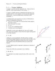
Chapter 24 continued<br />
Challenge Problem<br />
page 656<br />
The figure shows two identical motors with a<br />
common shaft. For simplicity, the commutators<br />
are not shown. Each armature coil consists of<br />
48 turns of wire with rectangular dimensions of<br />
17 cm wide by 35 cm deep. The armature<br />
resistance is 12 . The red wire travels to the left<br />
(along half the width) and then back to the rear<br />
of the motor (along the depth). The magnetic<br />
field is 0.21 T. The diameter of the pulley is<br />
7.2 cm. A rope fixed to the pulley and the floor<br />
prevents the motor shaft from turning.<br />
Pulley<br />
S<br />
Spring<br />
scale<br />
S 1<br />
S<br />
Shaft<br />
N<br />
120 V<br />
1. Given F ILB, derive an equation for the<br />
torque on the armature for the position<br />
shown.<br />
Torque is defined as the product of the<br />
force and the lever arm. In the case of<br />
the motor armature position shown, the<br />
lever arm is equal to half of the width of<br />
the armature coil (the shaft is the center<br />
of rotation and is at the midpoint of the<br />
coil width). The length of the wire acted<br />
upon by the field is equal to the depth<br />
of the coil. This length is effectively<br />
increased by n, the number of turns in<br />
the coil. Finally, the torque is doubled<br />
because as one side is pushed up by<br />
the magnetic field, the other side is<br />
pushed down according to the third<br />
right-hand rule.<br />
2nBI(depth)(width/2)<br />
S 2<br />
N<br />
35 V<br />
Simplifying and replacing (depth)(width)<br />
with area, A, gives:<br />
nBIA<br />
The torque produced by the motor<br />
armature, in the position shown, is<br />
equal to the number of turns times the<br />
field strength times the armature current<br />
times the area of the armature coil.<br />
2. With S 1 closed and S 2 open, determine the<br />
torque on the shaft and the force on the<br />
spring scale.<br />
nBIA<br />
(48)(0.21 T)1 20<br />
V<br />
(0.35 m)(0.17 m)<br />
12<br />
<br />
6.0 Nm<br />
Because the shaft cannot turn, the system<br />
is in equilibrium and the force on<br />
the spring scale is found by considering<br />
half the pulley diameter:<br />
6.<br />
0 Nm<br />
Fspring scale 170 N<br />
0.<br />
036<br />
m<br />
3. With both switches closed, determine the<br />
torque on the shaft and the force on the<br />
spring scale.<br />
Both motors produce counterclockwise<br />
torque:<br />
1 (48)(0.21 T)1 20<br />
V<br />
(0.35 m)(0.17 m)<br />
12<br />
<br />
6.0 Nm<br />
2 (48)(0.21 T) 35<br />
V<br />
(0.35 m)(0.17 m)<br />
12<br />
<br />
1.7 Nm<br />
net 7.7 Nm counterclockwise<br />
7.<br />
7 Nm<br />
Fspring scale 210 N<br />
0.<br />
036<br />
m<br />
4. What happens to torque if the armature is<br />
in a different position?<br />
The torque is reduced when there is<br />
any rotation from the position shown<br />
because the lever arm is reduced. With<br />
90° rotation, the force on the armature<br />
will be up and down (canceling) with<br />
the effective lever arm equal to zero.<br />
With the shown position as 0°:<br />
nBIA cos <br />
500 <strong>Solutions</strong> <strong>Manual</strong> <strong>Physics</strong>: Principles and Problems<br />
Copyright © Glencoe/McGraw-Hill, a division of The McGraw-Hill Companies, Inc.