Physics Solutions Manual
Physics Solutions Manual
Physics Solutions Manual

You also want an ePaper? Increase the reach of your titles
YUMPU automatically turns print PDFs into web optimized ePapers that Google loves.
Copyright © Glencoe/McGraw-Hill, a division of The McGraw-Hill Companies, Inc.<br />
CHAPTER<br />
24 Magnetic Fields<br />
Practice Problems<br />
24.1 Magnets: Permanent and<br />
Temporary<br />
pages 643–651<br />
page 647<br />
1. If you hold a bar magnet in each hand and<br />
bring your hands close together, will the<br />
force be attractive or repulsive if the magnets<br />
are held in the following ways?<br />
a. the two north poles are brought close<br />
together<br />
repulsive<br />
b. a north pole and a south pole are<br />
brought together<br />
attractive<br />
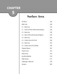
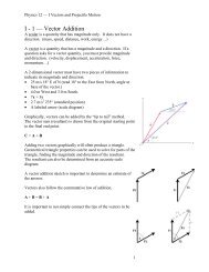
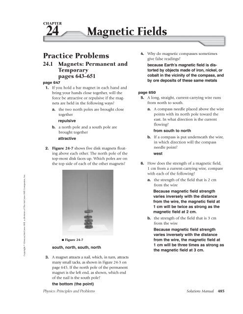
2. Figure 24-7 shows five disk magnets floating<br />
above each other. The north pole of the<br />
top-most disk faces up. Which poles are on<br />
the top side of each of the other magnets?<br />
■ Figure 24-7<br />
south, north, south, north<br />
3. A magnet attracts a nail, which, in turn, attracts<br />
many small tacks, as shown in Figure 24-3 on<br />
page 645. If the north pole of the permanent<br />
magnet is the left end, as shown, which end<br />
of the nail is the south pole?<br />
the bottom (the point)<br />
4. Why do magnetic compasses sometimes<br />
give false readings?<br />
because Earth’s magnetic field is distorted<br />
by objects made of iron, nickel, or<br />
cobalt in the vicinity of the compass, and<br />
by ore deposits of these same metals<br />
page 650<br />
5. A long, straight, current-carrying wire runs<br />
from north to south.<br />
a. A compass needle placed above the wire<br />
points with its north pole toward the<br />
east. In what direction is the current<br />
flowing?<br />
from south to north<br />
b. If a compass is put underneath the wire,<br />
in which direction will the compass<br />
needle point?<br />
<strong>Physics</strong>: Principles and Problems <strong>Solutions</strong> <strong>Manual</strong> 485<br />
west<br />
6. How does the strength of a magnetic field,<br />
1 cm from a current-carrying wire, compare<br />
with each of the following?<br />
a. the strength of the field that is 2 cm<br />
from the wire<br />
Because magnetic field strength<br />
varies inversely with the distance<br />
from the wire, the magnetic field at<br />
1 cm will be twice as strong as the<br />
magnetic field at 2 cm.<br />
b. the strength of the field that is 3 cm<br />
from the wire<br />
Because magnetic field strength<br />
varies inversely with the distance<br />
from the wire, the magnetic field at<br />
1 cm will be three times as strong as<br />
the magnetic field at 3 cm.
Chapter 24 continued<br />
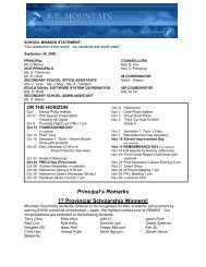
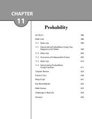
7. A student makes a magnet by winding wire<br />
around a nail and connecting it to a battery,<br />
as shown in Figure 24-13. Which end of<br />
the nail, the pointed end or the head, will<br />
be the north pole?<br />
■ Figure 24-13<br />
the pointed end<br />
<br />
8. You have a spool of wire, a glass rod, an<br />
iron rod, and an aluminum rod. Which rod<br />
should you use to make an electromagnet<br />
to pick up steel objects? Explain.<br />
Use the iron rod. Iron would be attracted<br />
to a permanent magnet and take on properties<br />
of a magnet, whereas aluminum or<br />
glass would not. This effect would support<br />
the magnetic field in the wire coil and<br />
thus make the strongest electromagnet.<br />
9. The electromagnet in problem 8 works well,<br />
but you decide that you would like to make its<br />
strength adjustable by using a potentiometer<br />
as a variable resistor. Is this possible? Explain.<br />
Yes. Connect the potentiometer in<br />
series with the power supply and the<br />
coil. Adjusting the potentiometer for<br />
more resistance will decrease the current<br />
flow and the strength of the field.<br />
Section Review<br />
24.1 Magnets: Permanent and<br />
Temporary<br />
pages 643–651<br />
page 651<br />
10. Magnetic Fields Is a magnetic field real, or<br />
is it just a means of scientific modeling?<br />
Field lines are not real. The field is real.<br />
11. Magnetic Forces Identify some magnetic<br />
forces around you. How could you demonstrate<br />
the effects of those forces?<br />
Student answers may vary. Answers<br />
could include magnets on a refrigerator<br />
and Earth’s magnetic field. The effects<br />
of these forces can be demonstrated by<br />
bringing another magnet, or a material<br />
that can be magnetized, nearby.<br />
12. Magnetic Fields A current-carrying wire is<br />
passed through a card on which iron filings<br />
are sprinkled. The filings show the magnetic<br />
field around the wire. A second wire is close<br />
to and parallel to the first wire. There is an<br />
identical current in the second wire. If the<br />
two currents are in the same direction, how<br />
will the first magnetic field be affected?<br />
How will it be affected if the two currents<br />
are in opposite directions?<br />
It would be approximately twice as<br />
large; it would be approximately zero.<br />
13. Direction of a Magnetic Field Describe<br />
the right-hand rule used to determine the<br />
direction of a magnetic field around a<br />
straight, current-carrying wire.<br />
If you grasp the wire with your right hand,<br />
with your thumb pointing in the direction<br />
of the conventional current, your fingers<br />
curl in the direction of the field.<br />
14. Electromagnets A glass sheet is placed<br />
over an active electromagnet, and iron filings<br />
sprinkled on the sheet create a pattern<br />
on it. If this experiment is repeated with the<br />
polarity of the power supply reversed, what<br />
observable differences will result? Explain.<br />
None. The filings would show the same<br />
field pattern but a compass would show<br />
the magnetic polarity reversal.<br />
15. Critical Thinking Imagine a toy containing<br />
two parallel, horizontal metal rods, one<br />
above the other. The top rod is free to move<br />
up and down.<br />
a. The top rod floats above the lower one. If<br />
the top rod’s direction is reversed, however,<br />
it falls down onto the lower rod. Explain<br />
why the rods could behave in this way.<br />
The metal rods could be magnets<br />
with their axes parallel. If the top<br />
486 <strong>Solutions</strong> <strong>Manual</strong> <strong>Physics</strong>: Principles and Problems<br />
Copyright © Glencoe/McGraw-Hill, a division of The McGraw-Hill Companies, Inc.
Copyright © Glencoe/McGraw-Hill, a division of The McGraw-Hill Companies, Inc.<br />
Chapter 24 continued<br />
magnet is positioned so that its<br />
north and south poles are above the<br />
north and south poles of the bottom<br />
magnet, it will be repelled and float<br />
above. If the top magnet is turned<br />
end for end, it will be attracted to the<br />
bottom magnet.<br />
b. Assume that the top rod was lost and<br />
replaced with another one. In this case,<br />
the top rod falls on top of the bottom<br />
rod no matter what its orientation is.<br />
What type of replacement rod must<br />
have been used?<br />
If an ordinary iron bar is used on<br />
top, it will be attracted to the bottom<br />
magnet in any orientation.<br />
Practice Problems<br />
24.2 Forces Caused by<br />
Magnetic Fields<br />
pages 652–659<br />
page 654<br />
16. What is the name of the rule used to predict<br />
the direction of force on a current-carrying<br />
wire at right angles to a magnetic field?<br />
Identify what must be known to use this rule.<br />
Third right-hand rule. The direction of<br />
the current and the direction of the field<br />
must be known.<br />
17. A wire that is 0.50 m long and carrying a<br />
current of 8.0 A is at right angles to a 0.40-T<br />
magnetic field. How strong is the force that<br />
acts on the wire?<br />
F BIL (0.40 N/Am)(8.0 A)(0.50 m)<br />
1.6 N<br />
18. A wire that is 75 cm long, carrying a current<br />
of 6.0 A, is at right angles to a uniform<br />
magnetic field. The magnitude of the force<br />
acting on the wire is 0.60 N. What is the<br />
strength of the magnetic field?<br />
F BIL<br />
F<br />
B <br />
IL<br />
0.<br />
60<br />
N<br />
0.13 T<br />
(6.0 A)<br />
( 0. 75 m)<br />
19. A 40.0-cm-long copper wire carries a current<br />
of 6.0 A and weighs 0.35 N. A certain<br />
magnetic field is strong enough to balance<br />
the force of gravity on the wire. What is the<br />
strength of the magnetic field?<br />
F BIL, where F weight of the wire<br />
F 0.<br />
35<br />
N<br />
B 0.15 T<br />
IL (6.0 A)<br />
( 0.400<br />
m)<br />
20. How much current will be required to produce<br />
a force of 0.38 N on a 10.0 cm length<br />
of wire at right angles to a 0.49-T field?<br />
F BIL<br />
F 0.38 N<br />
I 7.8 A<br />
BL<br />
(0.49 T)(0.100 m)<br />
page 658<br />
21. In what direction does the thumb point when<br />
using the third right-hand rule for an electron<br />
moving at right angles to a magnetic field?<br />
opposite to the direction of the electron<br />
motion<br />
22. An electron passes through a magnetic field<br />
at right angles to the field at a velocity of<br />
4.010 6 m/s. The strength of the magnetic<br />
field is 0.50 T. What is the magnitude of the<br />
force acting on the electron?<br />
F Bqv<br />
(0.50 T)(1.6010 19 C)(4.010 6 m/s)<br />
3.210 13 N<br />
23. A stream of doubly ionized particles (missing<br />
two electrons, and thus, carrying a net<br />
charge of two elementary charges) moves at<br />
a velocity of 3.010 4 m/s perpendicular to<br />
a magnetic field of 9.010 2 T. What is the<br />
magnitude of the force acting on each ion?<br />
F Bqv<br />
(9.010 2 T)(2)(1.6010 19 C)<br />
(3.010 4 m/s)<br />
8.610 16 N<br />
24. Triply ionized particles in a beam carry a<br />
net positive charge of three elementary<br />
charge units. The beam enters a magnetic<br />
field of 4.010 2 T. The particles have a<br />
speed of 9.010 6 m/s. What is the magnitude<br />
of the force acting on each particle?<br />
<strong>Physics</strong>: Principles and Problems <strong>Solutions</strong> <strong>Manual</strong> 487
Chapter 24 continued<br />
F Bqv<br />
(4.010 2 T)(3)(1.6010 19 C)<br />
(9.010 6 m/s)<br />
1.710 13 N<br />
25. Doubly ionized helium atoms (alpha particles)<br />
are traveling at right angles to a magnetic<br />
field at a speed of 4.010 4 m/s. The<br />
field strength is 5.010 2 T. What force<br />
acts on each particle?<br />
F Bqv<br />
(5.010 2 T)(2)(1.6010 19 C)<br />
(4.010 4 m/s)<br />
6.410 16 N<br />
Section Review<br />
24.2 Forces Caused by<br />
Magnetic Fields<br />
pages 652–659<br />
page 659<br />
26. Magnetic Forces Imagine that a currentcarrying<br />
wire is perpendicular to Earth’s<br />
magnetic field and runs east-west. If the current<br />
is east, in which direction is the force<br />
on the wire?<br />
up, away from the surface of Earth<br />
27. Deflection A beam of electrons in a<br />
cathode-ray tube approaches the deflecting<br />
magnets. The north pole is at the top of the<br />
tube; the south pole is on the bottom. If you<br />
are looking at the tube from the direction of<br />
the phosphor screen, in which direction are<br />
the electrons deflected?<br />
to the left side of the screen<br />
28. Galvanometers Compare the diagram of a<br />
galvanometer in Figure 24-18 on page 655<br />
with the electric motor in Figure 24-20 on<br />
page 656. How is the galvanometer similar<br />
to an electric motor? How are they different?<br />
Both the galvanometer and the electric<br />
motor use a loop of wire positioned<br />
between the poles of a permanent magnet.<br />
When a current passes through the<br />
loop, the magnetic field of the permanent<br />
magnet exerts a force on the loop.<br />
The loop in a galvanometer cannot<br />
rotate more than 180°. The loop in an<br />
electric motor rotates through many<br />
360° turns. The motor’s split-ring commutator<br />
allows the current in the loop to<br />
reverse as the loop becomes vertical in<br />
the magnetic field, enabling the loop to<br />
spin in the magnetic field. The galvanometer<br />
measures unknown currents;<br />
the electric motor has many uses.<br />
29. Motors When the plane of the coil in a<br />
motor is perpendicular to the magnetic<br />
field, the forces do not exert a torque on the<br />
coil. Does this mean that the coil does not<br />
rotate? Explain.<br />
Not necessarily; if the coil is already in<br />
rotation, then rotational inertia will carry<br />
it past the point of zero torque. It is the<br />
coil’s acceleration that is zero, not the<br />
velocity.<br />
30. Resistance A galvanometer requires 180 A<br />
for full-scale deflection. What is the total<br />
resistance of the meter and the multiplier<br />
resistor for a 5.0-V full-scale deflection?<br />
V 50 V<br />
R 28 k<br />
I 180 A<br />
31. Critical Thinking How do you know that<br />
the forces on parallel current-carrying wires<br />
are a result of magnetic attraction between<br />
wires, and not a result of electrostatics?<br />
Hint: Consider what the charges are like when<br />
the force is attractive. Then consider what the<br />
forces are when three wires carry currents in the<br />
same direction.<br />
If the currents are in the same direction,<br />
the force is attractive. If it were due to<br />
electrostatic forces, the like charges<br />
would make the force repulsive. Three<br />
wires would all attract each other, which<br />
could never happen if the forces were<br />
due to electrostatic charges.<br />
488 <strong>Solutions</strong> <strong>Manual</strong> <strong>Physics</strong>: Principles and Problems<br />
Copyright © Glencoe/McGraw-Hill, a division of The McGraw-Hill Companies, Inc.
Copyright © Glencoe/McGraw-Hill, a division of The McGraw-Hill Companies, Inc.<br />
Chapter 24 continued<br />
Chapter Assessment<br />
Concept Mapping<br />
page 664<br />
32. Complete the following concept map using<br />
the following: right-hand rule, F qvB, and<br />
F ILB.<br />
current-carrying<br />
wire<br />
exerted on a<br />
Mastering Concepts<br />
page 664<br />
33. State the rule for magnetic attraction and<br />
repulsion. (24.1)<br />
Like poles repel one another; opposite<br />
poles attract.<br />
34. Describe how a temporary magnet differs<br />
from a permanent magnet. (24.1)<br />
A temporary magnet is like a magnet<br />
only while under the influence of<br />
another magnet. A permanent magnet<br />
needs no outside influence.<br />
35. Name the three most important common<br />
magnetic elements. (24.1)<br />
iron, cobalt, and nickel<br />
moving charge<br />
has a has a<br />
has a<br />
magnitude direction magnitude<br />
F ILB<br />
Force<br />
resulting from<br />
a magnetic field<br />
given by given by given by<br />
right-hand<br />
rule<br />
F qvB<br />
36. Draw a small bar magnet and show the<br />
magnetic field lines as they appear around<br />
the magnet. Use arrows to show the direction<br />
of the field lines. (24.1)<br />
N S<br />
37. Draw the magnetic field between two like<br />
magnetic poles and then between two<br />
unlike magnetic poles. Show the directions<br />
of the fields. (24.1)<br />
N N<br />
N S<br />
38. If you broke a magnet in two, would you<br />
have isolated north and south poles?<br />
Explain. (24.1)<br />
No, new poles would form on each of<br />
the broken ends.<br />
39. Describe how to use the first right-hand rule<br />
to determine the direction of a magnetic field<br />
around a straight current-carrying wire. (24.1)<br />
Grasp the wire with the right hand,<br />
keeping thumb pointing in the direction<br />
of the conventional current through the<br />
wire. Fingers will encircle the wire and<br />
point in the direction of the field.<br />
40. If a current-carrying wire is bent into a<br />
loop, why is the magnetic field inside the<br />
loop stronger than the magnetic field outside?<br />
(24.1)<br />
The magnetic field lines are concentrated<br />
inside the loop.<br />
41. Describe how to use the second right-hand<br />
rule to determine the polarity of an electromagnet.<br />
(24.1)<br />
<strong>Physics</strong>: Principles and Problems <strong>Solutions</strong> <strong>Manual</strong> 489
Chapter 24 continued<br />
Grasp the coil with the right hand, keeping<br />
the fingers encircling the coil in the<br />
direction of the conventional current<br />
flow through the loops. The thumb of<br />
the right hand will point toward the<br />
north pole of the electromagnet.<br />
42. Each electron in a piece of iron is like a tiny<br />
magnet. The iron, however, may not be a<br />
magnet. Explain. (24.1)<br />
The electrons are not all oriented and<br />
moving in the same direction; their<br />
magnetic fields have random directions.<br />
43. Why will dropping or heating a magnet<br />
weaken it? (24.1)<br />
The domains are jostled out of alignment.<br />
44. Describe how to use the third right-hand<br />
rule to determine the direction of force on a<br />
current-carrying wire placed in a magnetic<br />
field. (24.2)<br />
Point the fingers of your right hand in<br />
the direction of the magnetic field. Point<br />
your thumb in the direction of the conventional<br />
current in the wire. The palm<br />
of your hand then faces in the direction<br />
of the force on the wire.<br />
45. A strong current suddenly is switched on in a<br />
wire. No force acts on the wire, however. Can<br />
you conclude that there is no magnetic field<br />
at the location of the wire? Explain. (24.2)<br />
No, if a field is parallel to the wire, no<br />
force would result.<br />
46. What kind of meter is created when a shunt<br />
is added to a galvanometer? (24.2)<br />
an ammeter<br />
Applying Concepts<br />
pages 664–665<br />
47. A small bar magnet is hidden in a fixed<br />
position inside a tennis ball. Describe an<br />
experiment that you could do to find the<br />
location of the north pole and the south<br />
pole of the magnet.<br />
Use a compass. The north pole of the<br />
compass needle is attracted to the south<br />
pole of the magnet and vice versa.<br />
48. A piece of metal is attracted to one pole of a<br />
large magnet. Describe how you could tell<br />
whether the metal is a temporary magnet or<br />
a permanent magnet.<br />
Move it to the other pole. If the same<br />
end is attracted, it is a temporary<br />
magnet; if the same end is repelled and<br />
the other end is attracted, it is a permanent<br />
magnet.<br />
49. Is the magnetic force that Earth exerts on a<br />
compass needle less than, equal to, or<br />
greater than the force that the compass<br />
needle exerts on Earth? Explain.<br />
The forces are equal according to<br />
Newton’s third law.<br />
50. Compass Suppose you are lost in the<br />
woods but have a compass with you.<br />
Unfortunately, the red paint marking the<br />
north pole of the compass needle has worn<br />
off. You have a flashlight with a battery and<br />
a length of wire. How could you identify<br />
the north pole of the compass?<br />
Connect the wire to the battery so that the<br />
current is away from you in one section.<br />
Hold the compass directly above and<br />
close to that section of the wire. By the<br />
right-hand rule, the end of the compass<br />
needle that points right is the north pole.<br />
51. A magnet can attract a piece of iron that is<br />
not a permanent magnet. A charged rubber<br />
rod can attract an uncharged insulator.<br />
Describe the different microscopic processes<br />
producing these similar phenomena.<br />
The magnet causes the domains in the<br />
iron to point in the same direction. The<br />
charged rod separates the positive and<br />
negative charges in the insulator.<br />
52. A current-carrying wire runs across a laboratory<br />
bench. Describe at least two ways in<br />
which you could find the direction of the<br />
current.<br />
490 <strong>Solutions</strong> <strong>Manual</strong> <strong>Physics</strong>: Principles and Problems<br />
Copyright © Glencoe/McGraw-Hill, a division of The McGraw-Hill Companies, Inc.
Copyright © Glencoe/McGraw-Hill, a division of The McGraw-Hill Companies, Inc.<br />
Chapter 24 continued<br />
Use a compass to find the direction of<br />
the magnetic field. Bring up a strong<br />
magnet and find the direction of the force<br />
on the wire, then use the right-hand rule.<br />
53. In which direction, in relation to a magnetic<br />
field, would you run a current-carrying wire<br />
so that the force on it, resulting from the<br />
field, is minimized, or even made to be zero?<br />
Run the wire parallel to the magnetic field.<br />
54. Two wires carry equal currents and run parallel<br />
to each other.<br />
a. If the two currents are in opposite directions,<br />
where will the magnetic field<br />
from the two wires be larger than the<br />
field from either wire alone?<br />
The magnetic field will be larger anywhere<br />
between the two wires.<br />
b. Where will the magnetic field from both<br />
be exactly twice as large as from one wire?<br />
The magnetic field will be twice as<br />
large along a line directly between<br />
the wires that is equal in distance<br />
from each wire.<br />
c. If the two currents are in the same direction,<br />
where will the magnetic field be<br />
exactly zero?<br />
The magnetic field will be zero along<br />
a line directly between the wires that<br />
is equal in distance from each wire.<br />
55. How is the range of a voltmeter changed<br />
when the resistor’s resistance is increased?<br />
The range of the voltmeter increases.<br />
56. A magnetic field can exert a force on a<br />
charged particle. Can the field change the<br />
particle’s kinetic energy? Explain.<br />
No, the force is always perpendicular<br />
to the velocity. No work is done. The<br />
energy is not changed.<br />
57. A beam of protons is moving from the<br />
back to the front of a room. It is deflected<br />
upward by a magnetic field. What is the<br />
direction of the field causing the deflection?<br />
Facing the front of the room, the<br />
velocity is forward, the force is upward,<br />
and therefore, using the third right-hand<br />
rule, B is to the left.<br />
58. Earth’s magnetic field lines are shown in<br />
Figure 24-23. At what location, poles or<br />
equator, is the magnetic field strength<br />
greatest? Explain.<br />
South pole<br />
■ Figure 24-23<br />
Earth’s magnetic field strength is<br />
greatest at the poles. The field lines are<br />
closer together at the poles.<br />
Mastering Problems<br />
24.1 Magnets: Permanent and Temporary<br />
pages 665–666<br />
Level 1<br />
59. As the magnet below in Figure 24-24<br />
moves toward the suspended magnet, what<br />
will the magnet suspended by the string do?<br />
N N S<br />
■ Figure 24-24<br />
Move to the left or begin to turn. Like<br />
poles repel.<br />
60. As the magnet in Figure 24-25 moves<br />
toward the suspended magnet, what will the<br />
magnet that is suspended by the string do?<br />
<strong>Physics</strong>: Principles and Problems <strong>Solutions</strong> <strong>Manual</strong> 491<br />
S<br />
Magnetic pole<br />
S<br />
N<br />
Magnetic pole<br />
North pole
Chapter 24 continued<br />
S<br />
■ Figure 24-25<br />
Move to the right. Unlike poles attract.<br />
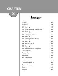
61. Refer to Figure 24-26 to answer the following<br />
questions.<br />
■ Figure 24-26<br />
a. Where are the poles?<br />
4 and 2, by definition<br />
b. Where is the north pole?<br />
2, by definition and field direction<br />
c. Where is the south pole?<br />
4, by definition and field direction<br />
62. Figure 24-27 shows the response of a compass<br />
in two different positions near a magnet.<br />
Where is the south pole of the magnet located?<br />
■ Figure 24-27<br />
At the right end, unlike poles attract.<br />
63. A wire that is 1.50 m long and carrying a<br />
current of 10.0 A is at right angles to a uniform<br />
magnetic field. The force acting on the<br />
wire is 0.60 N. What is the strength of the<br />
magnetic field?<br />
F ILB<br />
F<br />
B <br />
IL<br />
0.60<br />
N<br />
0.040 N/Am<br />
(10.0 A)(<br />
1.50<br />
m)<br />
0.040 T<br />
N<br />
3<br />
S<br />
1<br />
4 2<br />
N<br />
64. A conventional current flows through a<br />
wire, as shown in Figure 24-28. Copy the<br />
wire segment and sketch the magnetic field<br />
that the current generates.<br />
■ Figure 24-28<br />
65. The current is coming straight out of the<br />
page in Figure 24-29. Copy the figure and<br />
sketch the magnetic field that the current<br />
generates.<br />
■ Figure 24-29<br />
66. Figure 24-30 shows the end view of an electromagnet<br />
with current flowing through it.<br />
I<br />
I<br />
■ Figure 24-30<br />
492 <strong>Solutions</strong> <strong>Manual</strong> <strong>Physics</strong>: Principles and Problems<br />
I<br />
Copyright © Glencoe/McGraw-Hill, a division of The McGraw-Hill Companies, Inc.
Copyright © Glencoe/McGraw-Hill, a division of The McGraw-Hill Companies, Inc.<br />
Chapter 24 continued<br />
a. What is the direction of the magnetic<br />
field inside the loops?<br />
down into the page<br />
b. What is the direction of the magnetic<br />
field outside the loops?<br />
up (out of the page)<br />
Level 2<br />
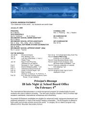
67. Ceramic Magnets The repulsive force<br />
between two ceramic magnets was measured<br />
and found to depend on distance, as given in<br />
Table 24-1.<br />
a. Plot the force as a function of distance.<br />
F (N)<br />
b. Does this force follow an inverse square<br />
law?<br />
No.<br />
4.0<br />
3.0<br />
2.0<br />
1.0<br />
0.0<br />
Table 24-1<br />
Separation, d (cm) Force, F (N)<br />
1.0 3.93<br />
1.2 0.40<br />
1.4 0.13<br />
1.6 0.057<br />
1.8 0.030<br />
2.0 0.018<br />
2.2 0.011<br />
2.4 0.0076<br />
2.6 0.0053<br />
2.8 0.0038<br />
3.0 0.0028<br />
1.0 1.4 1.8 2.2 2.6 3.0<br />
d (cm)<br />
24.2 Forces Caused by Magnetic Fields<br />
pages 666–667<br />
Level 1<br />
68. The arrangement shown in Figure 24-31 is<br />
used to convert a galvanometer to what<br />
type of device?<br />
■ Figure 24-31<br />
Ammeter, much of the current flows<br />
through the resistor and allows the<br />
measurement of higher currents.<br />
69. What is the resistor shown in Figure 24-31<br />
called?<br />
Shunt; by definition shunt is another<br />
word for parallel.<br />
70. The arrangement shown in Figure 24-32 is<br />
used to convert a galvanometer to what<br />
type of device?<br />
■ Figure 24-32<br />
Voltmeter; the added resistance<br />
decreases the current for any given<br />
voltage.<br />
71. What is the resistor shown in Figure 24-32<br />
called?<br />
Multiplier; by definition since it multiplies<br />
the voltage range of the meter<br />
72. A current-carrying wire is placed between the<br />
poles of a magnet, as shown in Figure 24-33.<br />
What is the direction of the force on the wire?<br />
<strong>Physics</strong>: Principles and Problems <strong>Solutions</strong> <strong>Manual</strong> 493<br />
G<br />
G
Chapter 24 continued<br />
■ Figure 24-33<br />
73. A wire that is 0.50 m long and carrying a<br />
current of 8.0 A is at right angles to a uniform<br />
magnetic field. The force on the wire<br />
is 0.40 N. What is the strength of the magnetic<br />
field?<br />
F ILB<br />
NN<br />
NN<br />
F 0.40 N<br />
B 0.10 T<br />
IL<br />
(8.0 A)(0.50 m)<br />
74. The current through a wire that is 0.80 m<br />
long is 5.0 A. The wire is perpendicular to a<br />
0.60-T magnetic field. What is the magnitude<br />
of the force on the wire?<br />
F ILB (5.0 A)(0.80 m)(0.60 N/Am)<br />
2.4 N<br />
75. A wire that is 25 cm long is at right angles<br />
to a 0.30-T uniform magnetic field. The current<br />
through the wire is 6.0 A. What is the<br />
magnitude of the force on the wire?<br />
F ILB (6.0 A)(0.25 m)(0.30 N/Am)<br />
0.45 N<br />
I<br />
I<br />
76. A wire that is 35 cm long is parallel to a<br />
0.53-T uniform magnetic field. The current<br />
through the wire is 4.5 A. What force acts<br />
on the wire?<br />
F<br />
SS<br />
SS<br />
If the wire is parallel to the field, no<br />
cutting is taking place, so no force is<br />
produced.<br />
77. A wire that is 625 m long is perpendicular<br />
to a 0.40-T magnetic field. A 1.8-N force acts<br />
on the wire. What current is in the wire?<br />
F ILB<br />
F 1.8<br />
N<br />
I <br />
BL<br />
(0.40 T)(625<br />
m)<br />
0.0072 A<br />
7.2 mA<br />
78. The force on a 0.80-m wire that is perpendicular<br />
to Earth’s magnetic field is 0.12 N.<br />
What is the current in the wire? Use<br />
5.010 5 T for Earth’s magnetic field.<br />
F ILB<br />
F<br />
I <br />
BL<br />
3.010 3 A<br />
3.0 kA<br />
79. The force acting on a wire that is at right<br />
angles to a 0.80-T magnetic field is 3.6 N.<br />
The current in the wire is 7.5 A. How long<br />
is the wire?<br />
F ILB<br />
F 3.6 N<br />
L 0.60 m<br />
BI<br />
(0.80 T)(7.5 A)<br />
Level 2<br />
80. A power line carries a 225-A current from<br />
east to west, parallel to the surface of Earth.<br />
a. What is the magnitude of the force<br />
resulting from Earth’s magnetic field<br />
acting on each meter of the wire? Use<br />
B Earth 5.010 5 T.<br />
F ILB<br />
0.12 N<br />
<br />
(5.010 5 T)(0.80 m)<br />
F<br />
L IB (225 A)(5.0105 T)<br />
0.011 N/m<br />
b. What is the direction of the force?<br />
The force would be downward.<br />
c. In your judgment, would this force be<br />
important in designing towers to hold<br />
this power line? Explain.<br />
No; the force is much smaller than<br />
the weight of the wires.<br />
494 <strong>Solutions</strong> <strong>Manual</strong> <strong>Physics</strong>: Principles and Problems<br />
Copyright © Glencoe/McGraw-Hill, a division of The McGraw-Hill Companies, Inc.
Copyright © Glencoe/McGraw-Hill, a division of The McGraw-Hill Companies, Inc.<br />
Chapter 24 continued<br />
81. Galvanometer A galvanometer deflects<br />
full-scale for a 50.0-A current.<br />
a. What must be the total resistance of the<br />
series resistor and the galvanometer to<br />
make a voltmeter with 10.0-V full-scale<br />
deflection?<br />
V IR<br />
R V<br />
I 2.00105 10.0 V<br />
<br />
<br />
50.0106 A<br />
2.0010 2 k<br />
b. If the galvanometer has a resistance of<br />
1.0 k, what should be the resistance of<br />
the series (multiplier) resistor?<br />
Total resistance 2.0010 2 k, so<br />
the series resistor is 2.0010 2 k <br />
1.0 k 199 k.<br />
82. The galvanometer in problem 81 is used to<br />
make an ammeter that deflects full-scale for<br />
10 mA.<br />
a. What is the potential difference across the<br />
galvanometer (1.0 k resistance) when a<br />
current of 50 A passes through it?<br />
V IR (5010 6 A)(1.010 3 )<br />
0.05 V<br />
b. What is the equivalent resistance of parallel<br />
resistors having the potential difference<br />
calculated in a circuit with a total<br />
current of 10 mA?<br />
V IR<br />
R V 510<br />
5 <br />
I 2 V<br />
<br />
0.01 A<br />
c. What resistor should be placed parallel<br />
with the galvanometer to make the<br />
resistance calculated in part b?<br />
1<br />
R<br />
1<br />
R1<br />
1 1<br />
so<br />
R1<br />
1<br />
<br />
5 1<br />
1.0103<br />
<br />
<br />
1 1<br />
<br />
R R2<br />
so R 1 5 <br />
R2<br />
83. A beam of electrons moves at right angles to<br />
a magnetic field of 6.010 2 T. The electrons<br />
have a velocity of 2.510 6 m/s. What is the<br />
magnitude of the force on each electron?<br />
F Bqv<br />
(6.010 2 T)(1.610 19 C)<br />
(2.510 6 m/s)<br />
2.410 14 N<br />
84. Subatomic Particle A muon (a particle<br />
with the same charge as an electron) is<br />
traveling at 4.2110 7 m/s at right angles<br />
to a magnetic field. The muon experiences<br />
a force of 5.0010 12 N.<br />
a. How strong is the magnetic field?<br />
F qvB<br />
F<br />
B qv<br />
<strong>Physics</strong>: Principles and Problems <strong>Solutions</strong> <strong>Manual</strong> 495<br />
<br />
0.742 T<br />
b. What acceleration does the muon experience<br />
if its mass is 1.8810 28 kg?<br />
F ma<br />
F<br />
a <br />
m<br />
2.6610 16 m/s 2<br />
85. A singly ionized particle experiences a force<br />
of 4.110 13 N when it travels at right<br />
angles through a 0.61-T magnetic field.<br />
What is the velocity of the particle?<br />
F qvB<br />
F<br />
v <br />
Bq<br />
5.0010 12 N<br />
<br />
(1.6010 19 C)(4.2110 7 m/s)<br />
4.210 6 m/s<br />
5.0010 12 N<br />
<br />
1.8810 28 kg<br />
4.110 13 N<br />
<br />
(0.61 T)(1.6010 19 C)<br />
86. A room contains a strong, uniform magnetic<br />
field. A loop of fine wire in the room has<br />
current flowing through it. Assume that you<br />
rotate the loop until there is no tendency for<br />
it to rotate as a result of the field. What is the<br />
direction of the magnetic field relative to the<br />
plane of the coil?<br />
The magnetic field is perpendicular to<br />
the plane of the coil. The right-hand rule<br />
would be used to find the direction of<br />
the field produced by the coil. The field<br />
in the room is in the same direction.
Chapter 24 continued<br />
87. A force of 5.7810 16 N acts on an<br />
unknown particle traveling at a 90° angle<br />
through a magnetic field. If the velocity of<br />
the particle is 5.6510 4 m/s and the field is<br />
3.2010 2 T, how many elementary<br />
charges does the particle carry?<br />
F qvB<br />
F<br />
q <br />
Bv<br />
3.2010 19 C<br />
N (3.201019 1charge<br />
C) 1.601019 C<br />
2 charges<br />
Mixed Review<br />
pages 667–668<br />
Level 2<br />
88. A copper wire of insignificant resistance<br />
is placed in the center of an air gap<br />
between two magnetic poles, as shown<br />
in Figure 24-34. The field is confined<br />
to the gap and has a strength of 1.9 T.<br />
7.5 cm<br />
■ Figure 24-34<br />
a. Determine the force on the wire (direction<br />
and magnitude) when the switch is<br />
open.<br />
0 N. With no current, there is no magnetic<br />
field produced by the wire and<br />
copper is not a magnetic material.<br />
b. Determine the force on the wire (direction<br />
and magnitude) when the switch is<br />
closed.<br />
Up, 0.62 N. The direction of the force<br />
is given by the third right-hand rule.<br />
I <br />
V<br />
R<br />
F ILB <br />
5.7810 16 N<br />
<br />
(3.2010 2 T)(5.6510 4 m/s)<br />
N S<br />
VLB<br />
R<br />
5.5 Ω<br />
24 V<br />
<br />
0.62 N<br />
c. Determine the force on the wire (direction<br />
and magnitude) when the switch is<br />
closed and the battery is reversed.<br />
Down, 0.62 N. The direction of the<br />
force is given by the third right-hand<br />
rule and the magnitude of the force<br />
is the same as in part b.<br />
d. Determine the force on the wire (direction<br />
and magnitude) when the switch is<br />
closed and the wire is replaced with a different<br />
piece having a resistance of 5.5 .<br />
Up, 0.31 N. The direction of the force<br />
is given by the third right-hand rule.<br />
I <br />
F ILB <br />
<br />
(24 V)(0.075 m)(1.9 T)<br />
<br />
5.5 <br />
V<br />
R<br />
(24 V)(0.075 m)(1.9 T)<br />
<br />
5.5 5.5 <br />
0.31 N<br />
89. Two galvanometers are available. One has<br />
50.0-A full-scale sensitivity and the other<br />
has 500.0-A full-scale sensitivity. Both<br />
have the same coil resistance of 855 . Your<br />
challenge is to convert them to measure a<br />
current of 100.0 mA, full-scale.<br />
a. Determine the shunt resistor for the<br />
50.0-A meter.<br />
Find the voltage across the meter<br />
coil at full scale.<br />
V IR (50.0 A)(855 ) 0.0428 V<br />
Calculate the shunt resistor.<br />
V<br />
R <br />
I<br />
0.428 <br />
VLB<br />
R<br />
0.0428 V<br />
<br />
100.0 mA 50.0 A<br />
b. Determine the shunt resistor for the<br />
500.0-A meter.<br />
Find the voltage across the meter<br />
coil at full scale.<br />
V IR (500.0 A)(855 ) 0.428 V<br />
496 <strong>Solutions</strong> <strong>Manual</strong> <strong>Physics</strong>: Principles and Problems<br />
Copyright © Glencoe/McGraw-Hill, a division of The McGraw-Hill Companies, Inc.
Copyright © Glencoe/McGraw-Hill, a division of The McGraw-Hill Companies, Inc.<br />
Chapter 24 continued<br />
Calculate the shunt resistor.<br />
V<br />
R <br />
I<br />
4.30 <br />
c. Determine which of the two is better for<br />
actual use. Explain.<br />
The 50.0-A meter is better. Its<br />
much lower shunt resistance will do<br />
less to alter the total resistance of<br />
the circuit being measured. An ideal<br />
ammeter has a resistance of 0 .<br />
90. Subatomic Particle A beta particle (highspeed<br />
electron) is traveling at right angles to<br />
a 0.60-T magnetic field. It has a speed of<br />
2.510 7 m/s. What size force acts on the<br />
particle?<br />
F Bqv<br />
(0.60 T)(1.610 19 C)(2.510 7 m/s)<br />
2.410 12 N<br />
91. The mass of an electron is 9.1110 31 kg.<br />
What is the magnitude of the acceleration of<br />
the beta particle described in problem 90?<br />
F ma<br />
F<br />
a <br />
m<br />
2.610 18 m/s 2<br />
92. A magnetic field of 16 T acts in a direction<br />
due west. An electron is traveling due south<br />
at 8.110 5 m/s. What are the magnitude<br />
and the direction of the force acting on the<br />
electron?<br />
F Bqv<br />
(16 T)(1.610 19 C)(8.110 5 m/s)<br />
2.110 12 N, upward (right-hand<br />
rule—remembering that electron flow is<br />
opposite to current flow)<br />
93. Loudspeaker The magnetic field in a loudspeaker<br />
is 0.15 T. The wire consists of 250<br />
turns wound on a 2.5-cm-diameter cylindrical<br />
form. The resistance of the wire is 8.0 .<br />
Find the force exerted on the wire when<br />
15 V is placed across the wire.<br />
I <br />
V<br />
R<br />
0.428 V<br />
<br />
100.0 mA 500.0 A<br />
2.410 12 N<br />
<br />
9.1110 31 kg<br />
L (# of turns)(circumference) nd<br />
F BIL<br />
F BVnd<br />
<br />
R<br />
<strong>Physics</strong>: Principles and Problems <strong>Solutions</strong> <strong>Manual</strong> 497<br />
<br />
5.5 N<br />
94. A wire carrying 15 A of current has a length<br />
of 25 cm in a magnetic field of 0.85 T. The<br />
force on a current-carrying wire in a uniform<br />
magnetic field can be found using the<br />
equation F ILB sin . Find the force on<br />
the wire when it makes the following angles<br />
with the magnetic field lines of<br />
a. 90°<br />
F ILB sin <br />
b. 45°<br />
c. 0°<br />
(15 A)(0.25 m)(0.85 T)(sin 90°)<br />
3.2 N<br />
F ILB sin <br />
(15 A)(0.25 m)(0.85 T)(sin 45°)<br />
2.3 N<br />
sin 0° 0<br />
so F 0 N<br />
95. An electron is accelerated from rest through<br />
a potential difference of 20,000 V, which<br />
exists between plates P 1 and P 2 , shown in<br />
Figure 24-35. The electron then passes<br />
through a small opening into a magnetic<br />
field of uniform field strength, B. As indicated,<br />
the magnetic field is directed into<br />
the page.<br />
P 1<br />
Electron<br />
(0.15 T)(15 V)(250)()(0.025 m)<br />
<br />
8.0 <br />
P2 X X X X X X X<br />
X X X X X X X<br />
X X X X X X X<br />
X X X X X X X<br />
X X X X X X X<br />
X X X X X X X<br />
■ Figure 24-35<br />
a. State the direction of the electric field<br />
between the plates as either P 1 to P 2 or<br />
P 2 to P 1 .<br />
from P 2 to P 1
Chapter 24 continued<br />
b. In terms of the information given, calculate<br />
the electron’s speed at plate P 2 .<br />
KE qV (1.610 19 C)<br />
(20,000 J/C)<br />
3.210 15 J<br />
KE mv2 1<br />
<br />
2<br />
v (2)(3.210<br />
<br />
15 2KE<br />
J)<br />
<br />
m 9.111031 kg<br />
810 7 m/s<br />
c. Describe the motion of the electron<br />
through the magnetic field.<br />
clockwise<br />
Thinking Critically<br />
page 668<br />
96. Apply Concepts A current is sent through<br />
a vertical spring, as shown in Figure 24-36.<br />
The end of the spring is in a cup filled with<br />
mercury. What will happen? Why?<br />
■ Figure 24-36<br />
Mercury<br />
Spring<br />
When the current passes through the<br />
coil, the magnetic field increases and<br />
forces cause the spring to compress.<br />
The wire comes out of the mercury,<br />
the circuit opens, the magnetic field<br />
decreases, and the spring drops down.<br />
The spring will oscillate up and down.<br />
97. Apply Concepts The magnetic field produced<br />
by a long, current-carrying wire is<br />
represented by B (210 7 Tm/A)(I/d),<br />
where B is the field strength in teslas, I is<br />
the current in amps, and d is the distance<br />
from the wire in meters. Use this equation<br />
to estimate some magnetic fields that you<br />
encounter in everyday life.<br />
a. The wiring in your home seldom carries<br />
more than 10 A. How does the magnetic<br />
field that is 0.5 m from such a wire<br />
compare to Earth’s magnetic field?<br />
I 10 A, d 0.5 m, so<br />
B <br />
<br />
410 6 T<br />
Earth’s field is 510 5 T, so Earth’s<br />
field is about 12 times stronger than<br />
that of the wire.<br />
b. High-voltage power transmission lines<br />
often carry 200 A at voltages as high as<br />
765 kV. Estimate the magnetic field on<br />
the ground under such a line, assuming<br />
that it is about 20 m high. How does<br />
this field compare with a magnetic field<br />
in your home?<br />
I 200 A, d 20 m, so<br />
B <br />
<br />
(210 7 Tm/A)I<br />
d<br />
(210 7 Tm/A)(10 A)<br />
<br />
0.5 m<br />
(210 7 Tm/A)I<br />
d<br />
(210 7 Tm/A)(200 A)<br />
<br />
20 m<br />
210 6 T<br />
This is half as strong as the field in<br />
part a.<br />
c. Some consumer groups have recommended<br />
that pregnant women not use electric<br />
blankets in case the magnetic fields cause<br />
health problems. Estimate the distance<br />
that a fetus might be from such a wire,<br />
clearly stating your assumptions. If such a<br />
blanket carries 1 A, find the magnetic field<br />
at the location of the fetus. Compare this<br />
with Earth’s magnetic field.<br />
Assume only one wire runs over<br />
“the fetus, and use the center of the<br />
fetus (where the vital organs are) as<br />
a reference point. At an early stage,<br />
the fetus might be 5 cm from the<br />
blanket. At later stages, the center<br />
of the fetus may be 10 cm away.<br />
I 1 A, d 0.05 m, so<br />
B (2107 Tm/A)I<br />
<br />
d<br />
(2107 Tm/A)(1 A)<br />
<br />
0.05 m<br />
498 <strong>Solutions</strong> <strong>Manual</strong> <strong>Physics</strong>: Principles and Problems<br />
Copyright © Glencoe/McGraw-Hill, a division of The McGraw-Hill Companies, Inc.
Copyright © Glencoe/McGraw-Hill, a division of The McGraw-Hill Companies, Inc.<br />
Chapter 24 continued<br />
410 6 T<br />
Earth’s magnetic field of 510 5 T is<br />
about 12 times stronger.<br />
98. Add Vectors In almost all cases described<br />
in problem 97, a second wire carries the<br />
same current in the opposite direction. Find<br />
the net magnetic field that is a distance of<br />
0.10 m from each wire carrying 10 A. The<br />
wires are 0.01 m apart. Make a scale drawing<br />
of the situation. Calculate the magnitude<br />
of the field from each wire and use a<br />
right-hand rule to draw vectors showing the<br />
directions of the fields. Finally, find the vector<br />
sum of the two fields. State its magnitude<br />
and direction.<br />
B B<br />
B A<br />
B 1<br />
B 1<br />
<br />
<br />
0.10 m<br />
0.10 m<br />
From each wire I 10 A, d 0.10 m, so<br />
B 2105 T<br />
From the diagram, only the components<br />
parallel to the line from the center of<br />
the wires contribute to the net field<br />
strength. The component from each<br />
wire is B1 B sin , where sin <br />
0.005<br />
m<br />
0.05, so B<br />
0.10<br />
m<br />
1 (2105 T)<br />
(0.05) 1106 T. But, each wire contributes<br />
the same amount, so the total<br />
field is 2106 (210<br />
T, about 1/25 Earth’s field.<br />
7 Tm/A)(10 A)<br />
<br />
0.10 m<br />
Writing In <strong>Physics</strong><br />
page 668<br />
99. Research superconducting magnets and write<br />
a one-page summary of proposed future uses<br />
for such magnets. Be sure to describe any<br />
hurdles that stand in the way of the practical<br />
application of these magnets.<br />
<br />
<br />
Iin Wire B<br />
0.005 m<br />
0.005 m<br />
Wire A<br />
Iout Student answers may vary. Superconducting<br />
magnets currently are used<br />
in magnetic resonance imaging (MRI), a<br />
medical technology. They are being tested<br />
for use in magnetically levitated highspeed<br />
trains, and it is hoped that superconducting<br />
magnets will help to make<br />
nuclear fusion energy practical. A drawback<br />
of superconducting magnets is that<br />
they require extremely low temperatures<br />
(near absolute zero). Scientists are trying<br />
to develop materials that are superconductive<br />
at higher temperatures.<br />
Cumulative Review<br />
page 668<br />
100. How much work is required to move a<br />
charge of 6.4010 3 C through a potential<br />
difference of 2500 V? (Chapter 21)<br />
W qV (6.4010 3 C)(2500 V) 16 J<br />
101. The current flow in a 120-V circuit increases<br />
from 1.3 A to 2.3 A. Calculate the<br />
change in power. (Chapter 22)<br />
P IV<br />
P 1 I 1 V, P 2 I 2 V<br />
P P 2 P 1 I 2 V I 1 V<br />
V(I 2 I 1 )<br />
(120 V)(2.3 A 1.3 A)<br />
120 W<br />
102. Determine the total resistance of three,<br />
55- resistors connected in parallel and<br />
then series-connected to two 55- resistors<br />
connected in series. (Chapter 23)<br />
1<br />
Rparallel<br />
R parallel 18 <br />
1 1 1 1<br />
R R R 55 <br />
1 1<br />
<br />
55 55 <br />
R equiv R parallel R R<br />
18 55 55 <br />
128 <br />
3<br />
55 <br />
<strong>Physics</strong>: Principles and Problems <strong>Solutions</strong> <strong>Manual</strong> 499
Chapter 24 continued<br />
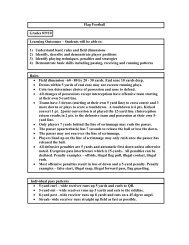
Challenge Problem<br />
page 656<br />
The figure shows two identical motors with a<br />
common shaft. For simplicity, the commutators<br />
are not shown. Each armature coil consists of<br />
48 turns of wire with rectangular dimensions of<br />
17 cm wide by 35 cm deep. The armature<br />
resistance is 12 . The red wire travels to the left<br />
(along half the width) and then back to the rear<br />
of the motor (along the depth). The magnetic<br />
field is 0.21 T. The diameter of the pulley is<br />
7.2 cm. A rope fixed to the pulley and the floor<br />
prevents the motor shaft from turning.<br />
Pulley<br />
S<br />
Spring<br />
scale<br />
S 1<br />
S<br />
Shaft<br />
N<br />
120 V<br />
1. Given F ILB, derive an equation for the<br />
torque on the armature for the position<br />
shown.<br />
Torque is defined as the product of the<br />
force and the lever arm. In the case of<br />
the motor armature position shown, the<br />
lever arm is equal to half of the width of<br />
the armature coil (the shaft is the center<br />
of rotation and is at the midpoint of the<br />
coil width). The length of the wire acted<br />
upon by the field is equal to the depth<br />
of the coil. This length is effectively<br />
increased by n, the number of turns in<br />
the coil. Finally, the torque is doubled<br />
because as one side is pushed up by<br />
the magnetic field, the other side is<br />
pushed down according to the third<br />
right-hand rule.<br />
2nBI(depth)(width/2)<br />
S 2<br />
N<br />
35 V<br />
Simplifying and replacing (depth)(width)<br />
with area, A, gives:<br />
nBIA<br />
The torque produced by the motor<br />
armature, in the position shown, is<br />
equal to the number of turns times the<br />
field strength times the armature current<br />
times the area of the armature coil.<br />
2. With S 1 closed and S 2 open, determine the<br />
torque on the shaft and the force on the<br />
spring scale.<br />
nBIA<br />
(48)(0.21 T)1 20<br />
V<br />
(0.35 m)(0.17 m)<br />
12<br />
<br />
6.0 Nm<br />
Because the shaft cannot turn, the system<br />
is in equilibrium and the force on<br />
the spring scale is found by considering<br />
half the pulley diameter:<br />
6.<br />
0 Nm<br />
Fspring scale 170 N<br />
0.<br />
036<br />
m<br />
3. With both switches closed, determine the<br />
torque on the shaft and the force on the<br />
spring scale.<br />
Both motors produce counterclockwise<br />
torque:<br />
1 (48)(0.21 T)1 20<br />
V<br />
(0.35 m)(0.17 m)<br />
12<br />
<br />
6.0 Nm<br />
2 (48)(0.21 T) 35<br />
V<br />
(0.35 m)(0.17 m)<br />
12<br />
<br />
1.7 Nm<br />
net 7.7 Nm counterclockwise<br />
7.<br />
7 Nm<br />
Fspring scale 210 N<br />
0.<br />
036<br />
m<br />
4. What happens to torque if the armature is<br />
in a different position?<br />
The torque is reduced when there is<br />
any rotation from the position shown<br />
because the lever arm is reduced. With<br />
90° rotation, the force on the armature<br />
will be up and down (canceling) with<br />
the effective lever arm equal to zero.<br />
With the shown position as 0°:<br />
nBIA cos <br />
500 <strong>Solutions</strong> <strong>Manual</strong> <strong>Physics</strong>: Principles and Problems<br />
Copyright © Glencoe/McGraw-Hill, a division of The McGraw-Hill Companies, Inc.