Position Stability of Surface Laid Submarine Optical Fiber Cables
Position Stability of Surface Laid Submarine Optical Fiber Cables
Position Stability of Surface Laid Submarine Optical Fiber Cables

You also want an ePaper? Increase the reach of your titles
YUMPU automatically turns print PDFs into web optimized ePapers that Google loves.
<strong>Position</strong> <strong>Stability</strong> <strong>of</strong> <strong>Surface</strong> <strong>Laid</strong> <strong>Submarine</strong> <strong>Optical</strong> <strong>Fiber</strong> <strong>Cables</strong><br />
Abstract<br />
Buried installation for submarine cable and optical fiber submarine<br />
cable is always a first choice, but when considering some other<br />
factors surface laid method is sometimes selected to install<br />
submarine cable. In such case, it is <strong>of</strong> great importance to consider<br />
the position stability <strong>of</strong> a submarine cable under water current. In<br />
this paper, a seabed touched submarine cable in marine current is<br />
analyzed by method <strong>of</strong> mechanics <strong>of</strong> fluids. The position stability <strong>of</strong><br />
surface laid submarine cable was analyzed. It is pointed out that the<br />
position stability <strong>of</strong> surface laid submarine cable depends on a cable<br />
structure parameter—a cable weight related parameter called<br />
position stability factor rather than cable weight. According to this<br />
consideration optical fiber submarine cable with higher position<br />
stability was designed and manufactured.<br />
Keywords: <strong>Submarine</strong> cable; optical fiber submarine cable;<br />
surface laid; position stability factor <strong>of</strong> submarine cable.<br />
1. Introduction<br />
Generally buried installation for submarine cable and optical fiber<br />
submarine cable is always a first choice since it could protect cables<br />
from various kinds <strong>of</strong> damage and ensure cable lifetime.<br />
But in practice, considering equipments, seabed topography or<br />
installation cost, surface laid method is selected to install submarine<br />
cable. For example, submarine power cables are <strong>of</strong>ten installed by<br />
surface laid method. Even for optical fiber submarine cables,<br />
trenching operation becomes much difficult in rocky seabed and<br />
deep sea, sometimes buried installation is not adopted, and cables<br />
are laid by cable ship, and then sink onto seabed.<br />
In order to repair the cable when fault is found, people need to know<br />
the exact position <strong>of</strong> submarine cable, so as to recover it. Therefore<br />
the study on position stability <strong>of</strong> surface laid submarine cable when<br />
exposed to water current is very important in practice. In this paper<br />
mechanics analysis is made on a horizontal cable surface laid on a<br />
flat horizontal seabed under the action <strong>of</strong> current.<br />
2. Mechanics Analysis<br />
The forces acting on a submarine cable laid on seabed under water<br />
current could be considered the forces acting on a horizontal laid<br />
cylinder laid on a flat horizontal bottom in a steady flow <strong>of</strong> viscous<br />
liquid.<br />
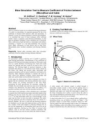
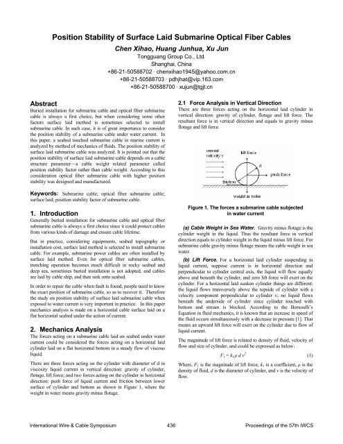
There are three forces acting on the cylinder with diameter <strong>of</strong> d in<br />
viscosity liquid current in vertical direction: gravity <strong>of</strong> cylinder,<br />
flotage, lift force; and two forces acting on the cylinder in horizontal<br />
direction: push force <strong>of</strong> liquid current and friction between lower<br />
surface <strong>of</strong> cylinder and bottom as shown in Figure 1, where the<br />
weight in water means gravity minus flotage.<br />
Chen Xihao, Huang Junhua, Xu Jun<br />
Tongguang Group Co., Ltd.<br />
Shanghai, China<br />
+86-21-50588702 · chenxihao1945@yahoo.com.cn<br />
+86-21-50588703 · pdhjhat@vip.163.com<br />
+86-21-50588700 · xujun@tgjt.cn<br />
2.1 Force Analysis in Vertical Direction<br />
There are three forces acting on the horizontal laid cylinder in<br />
vertical direction: gravity <strong>of</strong> cylinder, flotage and lift force. The<br />
resultant force is in vertical direction and equals to gravity minus<br />
flotage and lift force.<br />
Figure 1. The forces a submarine cable subjected<br />
in water current<br />
(a) Cable Weight in Sea Water. Gravity minus flotage is the<br />
cylinder weight in the liquid. Thus the resultant force in vertical<br />
direction equals to cylinder weight in the liquid minus lift force. For<br />
submarine cable gravity minus flotage means the cable weight in sea<br />
water.<br />
(b) Lift Force. For a horizontal laid cylinder suspending in<br />
liquid current, suppose current is in horizontal direction and<br />
perpendicular to cylinder central axis, the liquid will flow equally<br />
above and beneath the cylinder, and zero lift force will exert on the<br />
cylinder. For a horizontal laid sunken cylinder things are different:<br />
the liquid flows transversely above the topside <strong>of</strong> cylinder with a<br />
velocity component perpendicular to cylinder v; no liquid flows<br />
beneath the underside <strong>of</strong> cylinder since cylinder touched with<br />
bottom and stream is blocked. According to the Bernoulli’s<br />
Equation in fluid mechanics, it is known that an increase in speed <strong>of</strong><br />
the fluid occurs simultaneously with a decrease in pressure [1]. That<br />
means an upward lift force will exert on the cylinder due to flow <strong>of</strong><br />
liquid current.<br />
The magnitude <strong>of</strong> lift force is related to density <strong>of</strong> fluid, velocity <strong>of</strong><br />
flow and size <strong>of</strong> cylinder, and could be expressed as below:<br />
F1 = k1 ρ d v 2 (1)<br />
Where, F1 is the magnitude <strong>of</strong> lift force, k1 is a coefficient, ρ is the<br />
density <strong>of</strong> fluid, d is the diameter <strong>of</strong> cylinder, and v is the velocity <strong>of</strong><br />
flow.<br />
International Wire & Cable Symposium 436 Proceedings <strong>of</strong> the 57th IWCS
Thus, the resultant force exerted on cylinder in vertical direction<br />
becomes:<br />
W-F1 = W-k1 ρdv 2 (2)<br />
In equation (2), W represents the weight <strong>of</strong> cylinder in liquid.<br />
Normally, lift force is smaller than the weight <strong>of</strong> cylinder in the<br />
liquid, the direction <strong>of</strong> resultant force is in downward direction.<br />
Once lift force is larger than the weight <strong>of</strong> cylinder in the liquid, the<br />
cylinder will be lifted up, then the stream will flow beneath the<br />
cylinder, results lift force to zero.<br />
2.2 Force Analysis in Horizontal Direction<br />
For low velocity and laminar flow, the current push force acting on<br />
cylinder equals to viscous resistance, and could be expressed as:<br />
F2=k2 μ d v (3)<br />
Where F2 represents push force, k2 is a coefficient, μ is viscosity<br />
coefficient <strong>of</strong> fluid.<br />
For high velocity, when Reynolds Numbers beyond 4000, the flow<br />
is completely turbulent, and the push force acting on cylinder could<br />
be expressed as:<br />
F 3=k 3 ρ d v 2 (4)<br />
Where F3 represents push force, k3 is a coefficient.<br />
The maximum static friction force f between lower surface <strong>of</strong><br />
cylinder and bottom equals to:<br />
f = k (W- F1)= k (W-k1 ρ d v 2 ) (5)<br />
Where k is static friction coefficient and the meanings <strong>of</strong> other<br />
symbols are same as before.<br />
2.3 <strong>Position</strong> <strong>Stability</strong> Analysis<br />
The cylinder will remain at rest in condition that weight in water is<br />
large than lift force and the push force is less than friction, i. e:<br />
W-k1 ρdv 2 >0 and<br />
(6)<br />
F2 < f (for low velocity and laminar flow) (7)<br />
Substituting (3) and (5) to (7), we get:<br />
k2 μ v+ k k1 ρ v 2 < k W/d (8)<br />
Or<br />
W-k1 ρdv 2 >0 and<br />
(6)<br />
F3 < f (for high velocity and turbulent flow) (9)<br />
Substituting (4) and (5) to (9), we get:<br />
(k3 + k k1) ρ v 2 < k W/d (10)<br />
When push force equals to friction, inequalities (8) and (10) could<br />
be expressed as equations:<br />
k k1 ρ v 2 + k2 μ v - k W/d=0 (11)<br />
And (k3 + k k1) ρ v 2 - k W/d =0 (12)<br />
Mark vcl and vct as the solutions <strong>of</strong> equation (11) or equation (12),<br />
which represent critical velocity.<br />
The solution <strong>of</strong> equation (11) for laminar flow could be solved as:<br />
v cl<br />
=<br />
( k μ)<br />
2<br />
2<br />
2 ⎛W<br />
⎞<br />
+ 4k<br />
k1ρ<br />
⎜ ⎟ − k 2μ<br />
⎝ d ⎠<br />
2kk<br />
ρ<br />
The solution <strong>of</strong> equation (12) for turbulent flow could be solved as:<br />
v ct<br />
=<br />
k<br />
( k + kk )<br />
3<br />
1<br />
1<br />
⎛W<br />
⎜<br />
ρ ⎝ d<br />
⎞<br />
⎟<br />
⎠<br />
(13)<br />
(14)<br />
From equations (13) and (14) we know: if the velocity component<br />
<strong>of</strong> horizontal flow in perpendicular to cylinder axis direction is less<br />
than critical velocity, the cylinder will remain at rest, no movement<br />
will happen.<br />
In equation (13) and (14), density ρ <strong>of</strong> fluid and viscosity coefficient<br />
μ are parameters depend on the nature <strong>of</strong> fluid itself; W/d is ratio<br />
<strong>of</strong> weight <strong>of</strong> cylinder in liquid to diameter <strong>of</strong> cylinder; k1, k2 and<br />
k3 are parameters related to fluid and surface property <strong>of</strong> cylinder;<br />
static friction coefficient k is a parameter related to materials and<br />
surface roughness <strong>of</strong> contacting.<br />
Equation (13) and (14) could be rewritten as:<br />
vc = F(k, k1 ,k2, k3, μ, ρ, W/d) (15)<br />
From equation (15) we know that position stability <strong>of</strong> submarine<br />
cable is a function <strong>of</strong> fluid property, outer cover materials <strong>of</strong><br />
submarine cable and its surface property, density ρ and viscosity<br />
coefficient μ <strong>of</strong> seawater, and ratio <strong>of</strong> weight <strong>of</strong> cable in seawater<br />
to cable diameter.<br />
For submarine cables with same outer layer materials, to be<br />
placed onto same seabed, the parameter <strong>of</strong> k, k1 , k2, k3, μ and ρ<br />
are same, thus the position stability <strong>of</strong> cables only depend on their<br />
W/d, the ratio <strong>of</strong> weight <strong>of</strong> cable in seawater to cable diameter<br />
involved. W/d could be defined as position stability factor <strong>of</strong><br />
submarine cable. A submarine cable with bigger ratio <strong>of</strong> W/d could<br />
keep stationary at larger flow velocity.<br />
<strong>Position</strong> stability factor W/d is the measure <strong>of</strong> position stability for<br />
surface laid submarine cable.<br />
<strong>Position</strong> stability <strong>of</strong> submarine cable depends on W/d, the ratio <strong>of</strong><br />
cable weight in seawater to cable diameter rather than cable weight<br />
or cable weight in seawater.<br />
<strong>Cables</strong> with same position stability factor will have same position<br />
stability; a lighter cable with small diameter maybe has same even<br />
better position stability with a heavy cable with big diameter; among<br />
cables with same diameter the heavy one will have better position<br />
stability.<br />
3. Design Application<br />
In one area in East China Sea, an optical fibers submarine cable was<br />
planned to be laid on rocky seabed with maximum water depth <strong>of</strong><br />
100m and maximum current velocity <strong>of</strong> 1.81m/s. In this area many<br />
other submarine cables or pipes have been installed before and new<br />
submarine cable would cross with some <strong>of</strong> them The CBL (cable<br />
breaking load) requirement <strong>of</strong> cable is 450kN, and the fiber count is<br />
36. Because <strong>of</strong> such seabed situation, surface laid method is selected;<br />
the new cable will ask better position stability.<br />
To meet such application, an optical fiber submarine cable with<br />
three armoring layers was designed. The structure <strong>of</strong> this cable is<br />
shown in Figure 2 and could be further described as below:<br />
International Wire & Cable Symposium 437 Proceedings <strong>of</strong> the 57th IWCS
• Cable core: Stainless steel loose tube with 36 fibers. Inside <strong>of</strong><br />
tube water blocking compound is filled to prevent water ingress<br />
into the tube. HDPE is extruded over the stainless steel tube to<br />
insulate the tube. The nominal diameter <strong>of</strong> the insulation is<br />
10mm.<br />
• The first layer <strong>of</strong> armoring: The first layer <strong>of</strong> armoring consists<br />
<strong>of</strong> 12 high-tensile galvanized steel wires <strong>of</strong> 3.2mm nominal<br />
diameter. These wires are flooded with special bitumen<br />
compound and helically applied over the cable core with left<br />
hand lay direction.<br />
• Buffering layer: Buffering layer consists <strong>of</strong> polypropylene yarn<br />
applied over the first armoring layer.<br />
Figure 2. Cross-section structure <strong>of</strong> triple armored<br />
submarine cable<br />
• The second layer <strong>of</strong> armoring: The second layer <strong>of</strong> armoring<br />
consists <strong>of</strong> 12 high-tensile galvanized steel wires <strong>of</strong> 5.0mm<br />
nominal diameter. The wires are flooded with special bitumen<br />
compound and helically applied over the cable core with same<br />
lay direction as the first armoring.<br />
• The third layer <strong>of</strong> armoring: The third layer <strong>of</strong> armoring consists<br />
<strong>of</strong> 16 low-tensile galvanized steel wires <strong>of</strong> 6.0mm nominal<br />
diameter. The wires are flooded with special bitumen compound<br />
and helically applied over the cable core with same lay direction<br />
as the first armoring.<br />
• Outer serving: Outer serving consists <strong>of</strong> two layers <strong>of</strong><br />
polypropylene yarn helically applied over the armoring wires<br />
with opposite lay direction. Bitumen compound is flooded to the<br />
first layer <strong>of</strong> PP yarn. The finished cable is coated with talcum<br />
powder. The nominal cable diameter is 45mm.<br />
• Calculated position stability factor <strong>of</strong> the cable is 138kg/mm·km.<br />
Main characteristics <strong>of</strong> the optical fiber submarine cable are shown<br />
in Table 1, also listed in Table 1 are parameters <strong>of</strong> one double<br />
armored submarine cable and one single armored submarine cable<br />
for comparing. The double armored cable has similar structure as<br />
triple armored cable but without the third armoring, as shown in<br />
Figure 3. The single armored cable has similar structure as triple<br />
armored cable but without the second and the third armoring, as<br />
shown in Figure 4.<br />
According to calculating results listed in Table 1, we know the<br />
position stability factor <strong>of</strong> special designed triple armored<br />
submarine cable is double than that <strong>of</strong> the double armored cable and<br />
more than 4 times than that <strong>of</strong> the single armored cable.<br />
In structure <strong>of</strong> the triple armored cable, the main function <strong>of</strong> the<br />
first layer <strong>of</strong> armoring and the second layer <strong>of</strong> armoring is to<br />
provide cable mechanical strength, steel wires with high-tensile<br />
strength( better than 1200MPa) are used; and the main function <strong>of</strong><br />
the third layer <strong>of</strong> armoring is to provide cable position stability,<br />
increase W/d <strong>of</strong> the cable, steel wires with low-tensile strength<br />
( about 340MPa) are fit for such purpose, they provide lower cost<br />
and are easy to be armored compare with high-tensile steel wires<br />
while meet total CBL requirement <strong>of</strong> the cable.<br />
Figure 3. Cross-section structure <strong>of</strong> double armored<br />
submarine cable<br />
Figure 4. Cross-section structure <strong>of</strong> single armored<br />
submarine cable<br />
Table 1. Main structure parameters and characteristics <strong>of</strong><br />
three optical fiber submarine cables<br />
Item Unit<br />
Triple<br />
armored<br />
cable<br />
Double<br />
armored<br />
cable<br />
Single<br />
armored<br />
cable<br />
Core size mm 10 10 10<br />
1st layer<br />
armoring wires<br />
(1200MPa)<br />
2nd layer<br />
armoring wires<br />
(1200MPa)<br />
3rd layer<br />
armoring wires<br />
(340MPa)<br />
12 x<br />
3.2mm<br />
12 x<br />
5.0mm<br />
16 x<br />
6.0mm<br />
12 x<br />
3.2mm<br />
12 x<br />
5.0mm<br />
12 x<br />
3.2mm<br />
N/A<br />
N/A N/A<br />
Overall diameter mm 45 33 23<br />
CBL** kN 520 400 120<br />
NTTS** kN 310 240 72<br />
NOTS** kN 160 150 45<br />
Weight in air kg/m 7.85 3.1 1.1<br />
Weight in sea<br />
water*<br />
<strong>Position</strong> stability<br />
factor<br />
kg/m 6.23 2.23 0.67<br />
kg/mm·k<br />
m<br />
138 67 29<br />
* Density <strong>of</strong> sea water =1.023.<br />
** Definitions used are according to ITU-T G.972.<br />
International Wire & Cable Symposium 438 Proceedings <strong>of</strong> the 57th IWCS
The above designed three armored optical fiber submarine cable<br />
was manufactured by Tongguang Group and surface laid in sea<br />
area for already more than one year and has worked well.<br />
4. Conclusions<br />
In this paper the position stability <strong>of</strong> a surface laid submarine cable<br />
was analyzed by fluid mechanics method. It is shown that position<br />
stability <strong>of</strong> surface laid submarine cable depends on one cable<br />
structure parameter W/d, ratio <strong>of</strong> cable weight in water to cable<br />
diameter. It is suggested to call this parameter as position stability<br />
factor.<br />
According to such analysis, an optical fiber submarine cable with<br />
better position stability was designed, fabricated and surface laid in<br />
East China Sea for more than 1 year and has worked well. The main<br />
function <strong>of</strong> the 3 rd layer <strong>of</strong> armoring in the cable structure is to<br />
increase W/d <strong>of</strong> the cable. The position stability factor <strong>of</strong> the cable<br />
was calculated and compared with that <strong>of</strong> corresponding double<br />
armored cable and single armored cable.<br />
All the coefficients appeared in the formula could be obtained by<br />
further experiments, and it is believed that more detail engineering<br />
calculation will be possible.<br />
5. Acknowledgments<br />
Special thanks to Mr. Zhang Qiang <strong>of</strong> Tongguang Group for his<br />
support to this work and Mr. Li Wanmeng <strong>of</strong> Tongguang Group for<br />
helpful discussion.<br />
6. References<br />
[1] M C Potter, D C Wiggert and & M Hondzo, “ Mechanics <strong>of</strong><br />
Fluids” , 2 nd edition, Prentice Hall, 1997<br />
7. About the Authors<br />
Mr. Chen Xihao was<br />
born in Apr 1945 in<br />
Shanghai. He is<br />
senior engineer now.<br />
Mr. Chen graduated<br />
from the University<br />
<strong>of</strong> Science and<br />
Technology <strong>of</strong> China<br />
in 1967, and has been<br />
engaged in the field<br />
<strong>of</strong> optical fiber and<br />
optical fiber cable<br />
since 1976. He<br />
studied in Tohoku<br />
University ( Japan ) from 1984 to 1986. He worked for<br />
Shanghai Transmission Lines Research Institute from 1968 to<br />
1998, worked for Alcatel Shanghai <strong>Optical</strong> <strong>Fiber</strong> Cable Co., Ltd<br />
from 1998 to 2005. At present he works for Tongguang Group<br />
Company. His E-mail address is: chenxihao1945 @yahoo.com.cn<br />
Mr. Huang Junhua was<br />
born in Apr 1949 in<br />
Shanghai, he is senior<br />
engineer now. Mr.<br />
Huang graduated from<br />
Shanghai Construction<br />
Engineering School in<br />
1969 and studied in<br />
Shanghai University <strong>of</strong><br />
Science and<br />
Technology from 1982<br />
to 1985, and he has<br />
been engaged in the<br />
field <strong>of</strong> optical fiber<br />
and optical fiber cable since1976. He worked for Shanghai Quartz<br />
Glass Works from 1969 to 1985, worked for Shanghai <strong>Optical</strong><br />
<strong>Fiber</strong> Communication Company from 1986 to 1995, worked for<br />
Alcatel Shanghai <strong>Optical</strong> <strong>Fiber</strong> Cable Co., Ltd from 1995 to 2001.<br />
He has worked for Tongguang Group Company since 2002; he is<br />
Deputy General Manager <strong>of</strong> Tongguang Group Company now.<br />
His E-mail address is: pdhjhat@vip.163.com<br />
Mr. Xu Jun was born<br />
in 1977 in Haimen<br />
City, Jiangsu<br />
Province. He<br />
graduated from<br />
Nanjing University<br />
<strong>of</strong> Science and<br />
Technology in 1997.<br />
He has worked for<br />
Tongguang Group<br />
Company since 1999,<br />
and has been<br />
engaged in the field<br />
<strong>of</strong> optical fiber cable<br />
technology since<br />
then. Mr. Xu is Vise Chief Engineer <strong>of</strong> Tongguang Group<br />
Company now. His E-mail address is: xujun@tgjt.cn.<br />
International Wire & Cable Symposium 439 Proceedings <strong>of</strong> the 57th IWCS