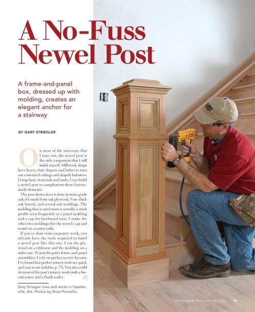
A No-Fuss Newel Post - Fine Homebuilding
A No-Fuss Newel Post - Fine Homebuilding
A No-Fuss Newel Post - Fine Homebuilding

You also want an ePaper? Increase the reach of your titles
YUMPU automatically turns print PDFs into web optimized ePapers that Google loves.
A <strong>No</strong>-<strong>Fuss</strong><br />
<strong>Newel</strong> <strong>Post</strong><br />
A frame-and-panel<br />
box, dressed up with<br />
molding, creates an<br />
elegant anchor for<br />
a stairway<br />
BY GARY STRIEGLER<br />
On most of the stairways that<br />
I trim out, the newel post is<br />
the only component that I still<br />
build myself. Millwork shops<br />
have heavy-duty shapers and lathes to turn<br />
out contoured railings and shapely balusters.<br />
Using basic materials and tools, I can build<br />
a newel post to complement these factorymade<br />
elements.<br />
The post shown here is done in stain-grade<br />
oak; it’s made from oak plywood, 3 ⁄4-in.-thick<br />
oak boards, and several oak moldings. The<br />
molding that is used most is actually a stock<br />
profile seen frequently as a panel molding<br />
and a cap for baseboard trim. I make the<br />
other two moldings (for the newel’s cap and<br />
waist) on a router table.<br />
If you’ve done trim-carpentry work, you<br />
already have the tools required to build<br />
a newel post like this one. I cut the plywood<br />
on a tablesaw and the molding on a<br />
miter saw. To join the post’s frame-and-panel<br />
assemblies, I rely on pocket screws because<br />
I’ve found that pocket-joinery tools are quick<br />
and easy to use (sidebar, p. 77). You also could<br />
do most of the post’s joinery work with a biscuit<br />
joiner and a finish nailer. <br />
Gary Striegler lives and works in Fayetteville,<br />
Ark. Photos by Brian Pontolilo.<br />
DECEMBER 2005/JANUARY 2006 75
Layout establishes<br />
post position and the<br />
railing’s plumb cut<br />
I notch the bottom of the<br />
newel to fit partially over<br />
the stairway’s first step.<br />
To my eye, this looks nicer<br />
than having the newel<br />
rest fully on the floor, and<br />
it’s less of an obstacle to<br />
folks turning the corner to<br />
go up the stairs. Strength<br />
is another benefit: The<br />
notched configuration<br />
offers multiple anchoring<br />
points when it comes time<br />
to install the post.<br />
When laying out the<br />
newel’s position, take<br />
baluster spacing into<br />
account and make sure<br />
that the centerline of the<br />
post is aligned with the<br />
centerline of the railing.<br />
To meet code in my<br />
area, the stair handrail<br />
should be between 32 in.<br />
and 34 in. from the tread,<br />
measured at the nosing<br />
(most codes now require<br />
34 in. to 38 in.). Taking<br />
into account the 7 3 ⁄8-in.<br />
rise of the stairway, I<br />
designed this newel post<br />
to create a top panel<br />
where the handrail could<br />
land and be fastened.<br />
You can mark the<br />
railing’s plumb cut by<br />
extending a vertical line<br />
from the notch position on<br />
the tread (photo below).<br />
76<br />
FINE HOMEBUILDING<br />
48 in.<br />
Plan view<br />
9 1 ⁄2 in.<br />
Elevation<br />
34 1 ⁄4 in.<br />
Railing<br />
<strong>No</strong>sing<br />
Mark the handrail’s plumb<br />
cut. Once the newel location<br />
is marked on the tread,<br />
you can mark the handrail’s<br />
plumb cut. Lay the railing<br />
on the treads to get its final<br />
installation angle. Place the<br />
square where the notched<br />
newel will fit, allowing<br />
for the 3 ⁄4-in. panel recess<br />
where the newel will be fastened.<br />
Then mark the cut.<br />
THE NEWEL POST STARTS OUT AS A<br />
Centerline<br />
34 in.<br />
2 1 ⁄2 in.<br />
The post is a hollow box made by joining four<br />
frame-and-panel sides together. Each side consists<br />
of a pair of 48-in.-long stiles and three rails. The<br />
bottom rail doesn’t need to extend all the way to<br />
the bottom of the box because this open area will<br />
be covered later by base molding. Stiles need to<br />
show the same finished width (1 3 ⁄4 in.) on all sides<br />
Top rail<br />
Top<br />
panel<br />
Bottom rail<br />
Middle<br />
rail<br />
Bottom<br />
panel<br />
8 3 ⁄4 in.<br />
3 in.<br />
1-in.-wide stile<br />
1 7 ⁄8-in.-wide stile<br />
Top<br />
panel<br />
Drawings: Bob La Pointe
FRAME-AND-PANEL BOX<br />
of the post, so two different stile widths are used.<br />
The 1 7 ⁄8-in.-wide stiles allow for a 1 ⁄8-in. overlap<br />
when I glue up the box. Routing away this excess<br />
material after the glue has dried gives me an<br />
almost invisible joint that makes two joining stiles<br />
look like a solid corner post.<br />
1 ⁄8-in.<br />
overhang<br />
Miter-cut<br />
panel edges<br />
Plan view of<br />
glued-up box<br />
Join stiles and rails<br />
with pocket screws.<br />
This locking-clamp<br />
setup is part of my<br />
pocket-joinery system<br />
(sidebar right). I use<br />
1 1 ⁄4-in. pan-head screws<br />
with self-drilling points<br />
to fasten rails to stiles.<br />
Fill the frames with<br />
plywood panels.<br />
Each side’s stile-andrail<br />
assembly gets a<br />
plywood panel glued<br />
against its inside face.<br />
I drive a few brads<br />
along each side to<br />
hold the panel in<br />
place while the<br />
glue dries.<br />
Glue and clamp up the box. Several<br />
1 1 ⁄4-in. brads keep each corner joint<br />
aligned while clamps are applied. The<br />
MDF block near the center of the box<br />
prevents clamp pressure from bending<br />
the stiles.<br />
Rout corners with a flush-trim bit.<br />
A planned corner overhang when<br />
assembling the box allows me to rout<br />
flush corners after the glue dries.<br />
POCKET SCREWS<br />
CAN’T BE BEAT<br />
I use pocket screws primarily to<br />
assemble face frames, mitered<br />
trim, and cabinet cases,<br />
but they have<br />
many other uses<br />
as well. Pocket<br />
screws offer some<br />
significant advantages<br />
over other<br />
joinery methods:<br />
● Joints can be made quickly. It<br />
doesn’t take long to clamp the<br />
workpiece to a drilling guide,<br />
bore pocket holes, then screw the<br />
joint together. Unlike biscuit joinery,<br />
only half of the joint needs to<br />
be machined.<br />
● Pocket screws have plenty of<br />
holding power. Even in a narrow<br />
joint, there’s room for at least a<br />
pair of screws; additional screws<br />
increase strength.<br />
● Glue is optional, and clamping<br />
isn’t necessary. Because screws<br />
provide the clamping power, your<br />
project can proceed without waiting<br />
for glue to dry.<br />
● Perfect alignment is easy. The<br />
special locking clamps available<br />
with most kits do an excellent<br />
job of locking parts together prior<br />
to assembly.<br />
● Pocket joinery is affordable and<br />
portable. The only tool you need<br />
is a drill. Shown above, Kreg’s<br />
Rocket Jig Pocket Hole System<br />
($50) has the necessary parts for<br />
getting started: a two-hole guide,<br />
clamp, and drilling and driving<br />
bits and screws. The K3 Master<br />
System is also worth checking out<br />
(p. 38). My favorite accessory is<br />
the Bench Klamp ($35), which<br />
essentially turns a piece of 3 ⁄4-in.<br />
plywood into a drilling and assembly<br />
workstation with uses that go<br />
beyond pocket joinery. For more<br />
information, contact the Kreg<br />
Tool Company (800-447-8638;<br />
www.kregtool.com).<br />
DECEMBER 2005/JANUARY 2006 77
Mitered moldings<br />
dress up the box<br />
Of the three moldings<br />
used to finish off the<br />
newel, the panel molding<br />
is really the star player.<br />
A With flat edges on<br />
top and bottom, it can<br />
butt cleanly against<br />
other surfaces. Narrow<br />
shoulders along the belly<br />
and the bead create<br />
delicate shadowlines and<br />
make it possible to use<br />
the molding in different<br />
orientations. It’s surprising<br />
how the same profile can<br />
create different visual<br />
effects depending on<br />
how it’s used. The panel<br />
molding is mitered to fit<br />
inside the oak frames on<br />
each side of the post. It’s<br />
also used under and over<br />
the post cap and on top<br />
of the baseboard.<br />
The cap molding is<br />
assembled as a mitered<br />
frame that extends<br />
beyond the top of the<br />
post, also providing a<br />
base for the top. B This<br />
molding starts out as<br />
an oak 1x4. I create the<br />
profile on a router table,<br />
using a thumbnail bit.<br />
I wait until the post is<br />
installed to attach the<br />
waist molding. C This<br />
profile also was made on a<br />
router table, using a wavyedge<br />
bit. Similar stock<br />
profiles are available from<br />
lumber suppliers.<br />
The last trim to go on is<br />
the baseboard. D Mitered<br />
to fit around the post, this<br />
1x6 board is topped off<br />
with the panel molding.<br />
78<br />
FINE HOMEBUILDING<br />
B<br />
Cap molding<br />
The cap molding<br />
is created using a<br />
thumbnail router bit.<br />
Panel molding<br />
A<br />
Waist molding<br />
C<br />
Base molding<br />
Panel molding<br />
is a stock<br />
profile also<br />
used as a<br />
base cap.<br />
Waist<br />
molding has<br />
symmetrical<br />
contours cut<br />
with a wavyedge<br />
bit.<br />
C<br />
D<br />
B<br />
A<br />
A<br />
A<br />
A<br />
A<br />
A<br />
ADD MOLDINGS FOR<br />
The box is together, but it looks plain.<br />
Moldings will change that. Trimming out<br />
the post adds contours, shadowlines, and<br />
the sharply defined detail of mitered joints.<br />
Strength, delicacy, and good craftsmanship<br />
all are expressed in the final result.<br />
The railing and balusters will depend on<br />
the newel for strength and stability, so it’s<br />
critical to anchor the post solidly. I start<br />
the installation by cutting away the tread<br />
nosing in the notch area to make way for<br />
solid blocking. With this material glued and<br />
screwed to the floor and to the stair framing,<br />
I can notch the newel, lift it into position,<br />
and set about making it plumb in all<br />
directions as I drive installation screws.<br />
Cut the nosing.<br />
Removing the overhanging<br />
tread where<br />
the newel will fit<br />
makes way for blocking,<br />
which needs<br />
to be positioned<br />
precisely.<br />
<strong>No</strong>tch for a snug fit. The inner surfaces of the<br />
post need to fit against the blocking, and the<br />
notch shouldn’t show gaps where it butts against<br />
finished-stair surfaces.
ORNAMENTATION AND BLOCKING FOR INSTALLATION<br />
Make it plumb and<br />
solid. The post slips<br />
into position from<br />
above. Once it’s in<br />
place, I check for<br />
plumb on two adjacent<br />
sides. If minor<br />
adjustments are<br />
needed, I tap a shim<br />
beneath one of the<br />
post corners. To<br />
secure the post to its<br />
blocking, I drive 3-in.<br />
wood screws through<br />
the newel’s stiles and<br />
rails. Drill pilot holes<br />
for these screws to<br />
avoid splitting the<br />
wood. The screw<br />
heads later will be<br />
hidden by the baseboard<br />
trim.<br />
Insert shims<br />
under corners<br />
as necessary to<br />
plumb post.<br />
DECEMBER 2005/JANUARY 2006 79