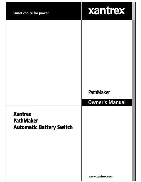
Xantrex PathMaker Automatic Battery Switch PathMaker Owner's ...
Xantrex PathMaker Automatic Battery Switch PathMaker Owner's ...
Xantrex PathMaker Automatic Battery Switch PathMaker Owner's ...

Create successful ePaper yourself
Turn your PDF publications into a flip-book with our unique Google optimized e-Paper software.
<strong>Xantrex</strong><br />
<strong>Xantrex</strong><br />
PathMak athMak athMaker athMak er<br />
<strong>Automatic</strong> <strong>Automatic</strong> <strong>Battery</strong> <strong>Battery</strong> <strong>Switch</strong><br />
<strong>Switch</strong><br />
<strong>PathMaker</strong><br />
<strong>Owner's</strong> Manual
2<br />
The Easy-to-Install <strong>Automatic</strong> <strong>Battery</strong> <strong>Switch</strong><br />
For Marine, RV, Alternative Energy<br />
and Car Audio use<br />
Pick the unit that’s right for your installation:<br />
100 Amps - 2 <strong>Battery</strong> Banks<br />
100 Amps - 3 <strong>Battery</strong> Banks<br />
250 Amps - 2 <strong>Battery</strong> Banks<br />
250 Amps - 3 <strong>Battery</strong> Banks<br />
Manual Contents<br />
Operations 4<br />
Installation 7<br />
Remotes 13<br />
Notice of Copyright<br />
<strong>Xantrex</strong> <strong>PathMaker</strong> <strong>Automatic</strong> <strong>Battery</strong> <strong>Switch</strong> © March 2004 <strong>Xantrex</strong> International All rights<br />
reserved <strong>Xantrex</strong> is a registered trademark of <strong>Xantrex</strong> International<br />
Disclaimer<br />
UNLESS SPECIFICALLY AGREED TO IN WRITING, XANTREX TECHNOLOGY INC<br />
(“XANTREX”)<br />
(a) MAKES NO WARRANTY AS TO THE ACCURACY, SUFFICIENCY OR<br />
SUITABILITY OF ANY TECHNICAL OR OTHER INFORMATION PROVIDED IN ITS<br />
MANUALS OR OTHER DOCUMENTATION<br />
(b) ASSUMES NO RESPONSIBILITY OR LIABILITY FOR LOSS OR DAMAGE,<br />
WHETHER DIRECT, INDIRECT, CONSEQUENTIAL OR INCIDENTAL, WHICH MIGHT ARISE<br />
OUT OF THE USE OF SUCH INFORMATION THE USE OF ANY SUCH INFORMATION WILL<br />
BE ENTIRELY AT THE USER’S RISK<br />
Date and Revision March 2004, Revision B Part Number 975-0119-01-01<br />
Contact Information Web: wwwxantrexcom Email: customerservice@xantrexcom<br />
Phone: 1 800 670 0707 (toll free in North America) 1 360 925 5097 (direct) Fax: 1 360 925 5143
Introduction<br />
The <strong>PathMaker</strong> provides automatic battery switching in a wide range of<br />
environments and applications including marine, recreational vehicles,<br />
renewable energy, military, and mobile audio The <strong>PathMaker</strong> has two<br />
primary functions—first, it automatically parallels (connects together)<br />
multiple batteries (combining them) when charging sources are available,<br />
and second, it automatically disconnects the starting battery from<br />
the system loads when there are no active charging sources This ensures<br />
that the engine starting battery is only used for starting Additionally,<br />
the <strong>PathMaker</strong> can be used to connect loads and sources<br />
The <strong>PathMaker</strong> consists of the following major components:<br />
A control module that provides user-adjustable set points, operator<br />
indicators, and a local control switch Additionally, a telephone jack<br />
on the right hand side of the module allows the user to plug in an optional<br />
remote control panel<br />
A terminal strip is fitted on the control module This terminal strip is<br />
where the user connects a negative wire to the terminal labeled negative<br />
(system ground), and makes optional connections All other connections<br />
are pre-wired at the factory and require no changes<br />
The <strong>PathMaker</strong> Power <strong>Switch</strong>(es) are mounted below the terminal<br />
strip They provide the connection for the path of battery current flow<br />
when enabled by the control module<br />
Remote Control Panel (optional) Use of this optional panel is strongly<br />
recommended, as the <strong>PathMaker</strong> may be mounted where access to<br />
the local control switch may not be convenient<br />
3
4<br />
Operations<br />
The <strong>PathMaker</strong> has power switch(es) that connect batteries,<br />
loads or sources together<br />
Connected Light<br />
The Connected light turns on to indicate that the batteries, loads or<br />
sources are connected<br />
Disabled Light<br />
The Disabled light is on whenever the power switch(es) is(are) not on<br />
High Voltage Disconnect Light<br />
The High Voltage Disconnect light is on solid whenever the batteries<br />
are not connected due to a voltage higher than the High Voltage<br />
Disconnect set point The High Voltage Disconnect light will flash<br />
based on the following condition If a charge source is connected to<br />
a smaller battery bank, it is possible that when the Pathmaker<br />
connects the banks together, the larger battery bank (or depleted<br />
battery bank) will pull the battery voltage down below the Low Voltage<br />
Disconnect Setpoint This will cause the unit to disconnect If this<br />
happens more than five times, the unit will shut down and the High<br />
Voltage Disconnect light will begin to flash After six minutes—to<br />
allow the battery connected to the charge source to charge longer—<br />
the unit will try to reconnect and resume normal operation<br />
The Control Module <strong>Switch</strong><br />
The switch on the Control Module should normally be in the Auto<br />
position If it is in the O (Disabled) position, the batteries will not<br />
connect when a charge source is available To test the <strong>PathMaker</strong><br />
hold the switch in the I (ON) position While the switch is in the I (ON)<br />
position, the power switch(es) will be on and the green “Connected”<br />
light will turn on If emergency starting is required, pushing the<br />
switch to the I (ON) position will momentarily connect the battery<br />
switches as long as the switch is held If two batteries are connected<br />
to the <strong>PathMaker</strong>, this provides a jump start for the starter<br />
Remember: The local switch on the <strong>PathMaker</strong> must be in the “AUTO”<br />
position for any remote switch to work
Setup and Operation<br />
Adjustments<br />
Default settings are at the<br />
12 o’clock position<br />
Low Voltage<br />
Disconnect*<br />
Below this voltage, the<br />
<strong>PathMaker</strong> power switch(es)<br />
is(are) disabled (the batteries<br />
are not connected together)<br />
The default voltage is set at<br />
130 V The yellow “disabled”<br />
light will be lit whenever the<br />
batteries level falls below the<br />
set point<br />
Negative<br />
CONNECT THE SYSTEM<br />
NEGATIVE (ground) TO<br />
THIS TERMINAL LAST<br />
(Use #14 AWG wire or larger)<br />
See Page 14<br />
Factory Installed<br />
5<br />
Connect Voltage*<br />
Above this voltage the <strong>PathMaker</strong><br />
power switch(es) are enabled: thus the<br />
batteries are in parallel for charging<br />
The default voltage setting is 133 V<br />
The green “connected” light is on<br />
whenever the banks are connected<br />
(Light may flicker below 126 V)<br />
High Voltage Disconnect*<br />
Above this voltage, the power<br />
switch(es) are disabled The<br />
default voltage setting is 150 V The<br />
red “High Voltage Disconnect”<br />
light is on solid when active<br />
Optional Remote<br />
See Page 13<br />
*Multiply voltage values times 2<br />
for use on 24 V systems
6<br />
Connecting with a Remote<br />
You can force the <strong>PathMaker</strong> to “Connect” for five minutes for<br />
emergency starting by momentarily pressing the “Manual On” switch<br />
on the remote panel You may cancel the forced connection only by<br />
pressing the “Manual On” switch a second time (for less than one<br />
second)<br />
While in the forced “Connect” mode, placing the switch to the<br />
“Disabled” position will break the connection However, returning<br />
the switch to the “Auto” position will allow the forced “Connect” to<br />
resume until the five-minute timer expires or until the switch is again<br />
placed over to the ON for at least one second to cancel the fiveminute<br />
timer<br />
Troubleshooting<br />
The <strong>PathMaker</strong> is internally protected against most faults If the Green<br />
light does not come on when the switch on the unit is held in the ON<br />
position, disconnect the wire connected to the system negative<br />
terminal, wait one minute and reconnect it
Installation<br />
The terms “battery” and “bank” are used interchangeably A “bank” means<br />
a group of batteries that are connected, in series or parallel, to create a<br />
higher capacity, or higher voltage, “battery” Installation requires three wires<br />
for two bank units and four wires for three bank units Generally no set up<br />
is required<br />
Connect the wire to system negative (ground) to the <strong>PathMaker</strong><br />
terminal strip last<br />
All wiring to <strong>PathMaker</strong> power switch terminals must be sufficiently<br />
sized Starter current of several hundred amps may pass through<br />
these wires If in doubt, please consult a professional<br />
<strong>Battery</strong> cables must be properly strain relieved Although no<br />
exposed contacts are used, the <strong>PathMaker</strong> is NOT approved for<br />
explosive environments<br />
CAUTION!! If B+ (<strong>Battery</strong> Positive) is shorted to the NEGATIVE<br />
terminal of the Control Module, COIL NEGATIVE, the electronics<br />
may be destroyed THIS IS NOT COVERED BY THE WARRANTY!<br />
Fuses, <strong>Battery</strong> <strong>Switch</strong>es, and Protective Terminal Caps<br />
To simplify installation diagrams we have not included fusing or optional<br />
on/off battery switches Check the latest ABYC (American Boat<br />
and Yacht Council) and NEC (National Electrical Code) for fusing<br />
requirements for your installation Install protective terminal caps<br />
as needed to protect against shorting of terminals<br />
Alternator Protection<br />
An alternator may be damaged if operated with no battery (or load)<br />
attached For this reason, we recommend the use of a <strong>Xantrex</strong><br />
ZapStop to protect an alternator that experiences a brief open output<br />
condition The ZapStop prevents momentary overvoltage<br />
7
8<br />
Power <strong>Switch</strong> Connections<br />
When wiring to the power switch(es), remove the supplied voltage<br />
sense leads and place your heavy battery wiring on the<br />
terminal post first Then replace the supplied voltage sense<br />
wire on top of the heavy battery wires This eliminates voltage<br />
sensing errors under high current conditions The drawings below<br />
indicate the terminal designations for each model May not be<br />
exactly as shown<br />
Batt, Load or<br />
Source #1<br />
(VB1)<br />
Batt, Load or<br />
Source #1<br />
(VB1)<br />
Batt, Load, or<br />
Source #1<br />
(VB1)<br />
Batt, Load or<br />
Source #1<br />
(VB1)<br />
100 Amp Two-<br />
Bank <strong>PathMaker</strong><br />
Batt, Load or<br />
Source #2 (VB2)<br />
250 Amp Two-<br />
Bank <strong>PathMaker</strong><br />
Batt, Load or<br />
Source #2 (VB2)<br />
100 Amp Three-<br />
Bank <strong>PathMaker</strong><br />
Batt, Load or Source<br />
#2 (VB2)<br />
Batt, Load or Source<br />
#3 (VB3)<br />
250 Amp Three-<br />
Bank <strong>PathMaker</strong><br />
<strong>Battery</strong>, Load or<br />
Source #3 (VB3)<br />
<strong>Battery</strong>, Load or<br />
Source #2 (VB2)
Diagram Table<br />
Many configurations are possible with a <strong>PathMaker</strong> This table is a<br />
guide to help select the correct diagram for your installation:<br />
System: Use Diagram Page<br />
2 Banks single or multi-engine Diagram 1 10<br />
(Marine, RV, Renewable Energy or Car Audio)<br />
3 Banks<br />
2 House, 1 Start Diagram 2 11<br />
1 House, 2 Start Diagram 3 12<br />
(Marine or RV)<br />
Sources such as battery chargers, solar panels, wind generators, or<br />
alternators may be wired to any battery When a battery’s voltage rises<br />
above the Connect Voltage all batteries are paralleled and charged by<br />
the source If there are multiple sources connected, the source with the<br />
highest voltage will charge the batteries to that level Alternators will<br />
not “fight” against each other; the batteries will simply charge at the voltage<br />
of the alternator having the highest output voltage<br />
9
10<br />
Diagram 1 (2 Banks)<br />
This is the recommended installation method In this diagram the<br />
starter is wired directly to the starting battery The battery switch always<br />
stays in the #1 position, the house battery supplies the DC<br />
loads The engine starting battery always supplies starting The<br />
<strong>PathMaker</strong> connects the batteries in parallel when a charging source<br />
is present and disconnects them when there is no charging source<br />
present<br />
The battery switch shown is not required but may be left installed as<br />
a redundant switch, if desired<br />
Note: Install Negative (ground) to <strong>PathMaker</strong> last<br />
Fusing, breakers, wire size, and optional battery switches that may be<br />
required by ABYC or NEC are not shown<br />
+<br />
NEGATIVE<br />
TO DC LOADS<br />
VB1<br />
+ -<br />
HOUSE<br />
C<br />
1 2<br />
- +<br />
START<br />
ENGINE<br />
PATHMAKER STARTER<br />
VB2<br />
ALT<br />
TO ENGINE(S)
Diagram 2 (3 Banks)<br />
This diagram shows an installation with one engine starting battery<br />
and two house banks This type of installation uses a three-bank<br />
version of the <strong>PathMaker</strong><br />
Note: Install Negative (ground) to <strong>PathMaker</strong> last<br />
Fusing, breakers, wire size, and optional battery switches that may be<br />
required by ABYC or NEC are not shown<br />
ALT<br />
ENGINE<br />
NEGATIVE<br />
VB1<br />
STARTER<br />
+ -<br />
HOUSE 1<br />
1<br />
C TO DC LOADS +<br />
2<br />
PATHMAKER<br />
+ -<br />
START<br />
VB2<br />
- +<br />
HOUSE 2<br />
VB3<br />
11
12<br />
Diagram 3 (3 Banks)<br />
In this twin engine, three-battery bank installation, each engine has a<br />
dedicated starting battery All batteries are charged when either of<br />
the engines is running, or when there is any charging source on the<br />
system In an emergency all batteries may be connected together<br />
using the optional Remote <strong>Switch</strong> This diagram is shown without<br />
any battery switches, since a <strong>PathMaker</strong> can replace battery switches<br />
Note: Install Negative (ground) to <strong>PathMaker</strong> last<br />
+<br />
Fusing, breakers, wire size, and optional battery switches that may be<br />
required by ABYC or NEC are not shown<br />
TO DC LOADS<br />
ALT<br />
ENGINE<br />
# 1<br />
NEGATIVE<br />
VB1<br />
STARTER<br />
+ -<br />
HOUSE<br />
PATHMAKER<br />
+ -<br />
START 1<br />
VB2<br />
- +<br />
START 2<br />
ENGINE<br />
# 2<br />
VB3<br />
ALT<br />
STARTER
Optional <strong>PathMaker</strong> Remote<br />
We highly recommend using the optional Remote Control <strong>Switch</strong> to<br />
provide a clear indication of the <strong>PathMaker</strong> status and to simplify<br />
emergency starting Please contact your dealer to purchase the<br />
Remote Control <strong>Switch</strong> panel<br />
Emergency Starting<br />
If you cannot start the engine, momentarily press the Manual On<br />
switch The <strong>PathMaker</strong> then connects all batteries together (for five<br />
minutes) to provide maximum starting power<br />
Using the <strong>PathMaker</strong> Remote<br />
Control Panel<br />
The <strong>PathMaker</strong> Remote switch<br />
is normally left in the AUTO<br />
position In this position the<br />
power switch(es) are<br />
energized (connecting the<br />
batteries together) when the<br />
“Connect” voltage is reached,<br />
and de-energized below the<br />
”Disconnect” voltage<br />
13<br />
Momentarily press switch in<br />
MANUAL ON position to turn on<br />
power switch(es)<br />
To disable <strong>PathMaker</strong><br />
To disable the <strong>PathMaker</strong><br />
switch to off position<br />
place the switch in the “O”<br />
[OFF] position In this position the battery banks are separated The<br />
yellow “Disabled” light is ON<br />
To manually energize the <strong>PathMaker</strong> power switch(es), momentarily<br />
press and hold the switch to the “I” [ON] position until the green ON<br />
light is lit (about one second) This connects the batteries for five minutes<br />
Moving the switch momentarily to the ON position for at least one<br />
second will cancel the five-minute connect timer
14<br />
User Remote <strong>Switch</strong><br />
You may use your own momentary<br />
pushbutton switch installed between the<br />
terminal labeled (Negative) and (Neg at<br />
Remote) to manually energize the <strong>PathMaker</strong><br />
power switch(es) Hold the pushbutton down<br />
for about 2 seconds to energize the<br />
<strong>PathMaker</strong> power switch(es) They will stay<br />
energized for 5 minutes Momentarily use the<br />
pushbutton again to de-energize the power<br />
switch(es)<br />
Monitor<br />
<br />
Momentary ON<br />
Pushbutton<br />
To DC Negative<br />
Low Voltage<br />
Disconnect<br />
13 .0<br />
12 .9<br />
13 .1<br />
12.8 13 .2<br />
Connect<br />
Voltage<br />
13 .1 13.5<br />
H i gh Vo l ta ge<br />
D i sc on ne ct<br />
High Voltage<br />
13 .3<br />
15.0<br />
Dis able d Connec ted Disconnect<br />
Auto<br />
13 .2<br />
13 .4<br />
14.5<br />
15.5<br />
O I<br />
14.0 16.0<br />
Mu tp y vo tage settng s X2 for 24V use<br />
Monitor Solenoid Wiring<br />
<br />
<br />
The Control Module <strong>Switch</strong><br />
The local switch on the <strong>PathMaker</strong> must<br />
be in the “AUTO” position for the remote<br />
switch to work<br />
Disabled Connected<br />
Solenoid Wiring<br />
High Voltage<br />
Disconnect<br />
Auto<br />
25 0 A mp, 3 Bat ter y<br />
<strong>Automatic</strong> <strong>Switch</strong><br />
w ww.xa nt re x.com<br />
O I<br />
250 Amp, 3 <strong>Battery</strong><br />
<strong>Automatic</strong> <strong>Switch</strong><br />
www.xantrex.com
Warranty<br />
What does this warranty cover? This Limited Warranty is provided by <strong>Xantrex</strong> Technology, Inc<br />
(“<strong>Xantrex</strong>”) and covers defects in workmanship and materials in your <strong>Xantrex</strong> <strong>PathMaker</strong><br />
<strong>Automatic</strong> <strong>Battery</strong> <strong>Switch</strong> This warranty lasts for a Warranty Period of 12 months from the date<br />
of purchase at point of sale to you, the original end user customer<br />
This Limited Warranty is transferable to subsequent owners but only for the unexpired portion of the<br />
Warranty Period<br />
What will <strong>Xantrex</strong> do? <strong>Xantrex</strong> will, at its option, repair or replace the defective product free of<br />
charge, provided that you notify <strong>Xantrex</strong> of the product defect within the Warranty Period, and<br />
provided that <strong>Xantrex</strong> through inspection establishes the existence of such a defect and that it is<br />
covered by this Limited Warranty<br />
<strong>Xantrex</strong> will, at its option, use new and/or reconditioned parts in performing warranty repair and<br />
building replacement products <strong>Xantrex</strong> reserves the right to use parts or products of original or<br />
improved design in the repair or replacement If <strong>Xantrex</strong> repairs or replaces a product, its warranty<br />
continues for the remaining portion of the original Warranty Period or 90 days from the date of the<br />
return shipment to the customer, whichever is greater All replaced products and all parts removed<br />
from repaired products become the property of <strong>Xantrex</strong><br />
<strong>Xantrex</strong> covers both parts and labor necessary to repair the product, and return shipment to the<br />
customer via a <strong>Xantrex</strong>-selected non-expedited surface freight within the contiguous United States<br />
and Canada Alaska and Hawaii are excluded Contact <strong>Xantrex</strong> Customer Service for details on<br />
freight policy for return shipments outside of the contiguous United States and Canada<br />
How do you get service? If your product requires troubleshooting or warranty service, contact your<br />
merchant If you are unable to contact your merchant, or the merchant is unable to provide service,<br />
contact <strong>Xantrex</strong> directly at:<br />
Phone: 1 800 670 0707 (toll free in North America), 1 360 925 5097 (direct)<br />
Fax: 1 360 925 5143<br />
Email: Customerservice@xantrexcom<br />
Direct returns may be performed according to the <strong>Xantrex</strong> Return Material Authorization Policy<br />
described in your product manual For some products, <strong>Xantrex</strong> maintains a network of regional<br />
Authorized Service Centers Call <strong>Xantrex</strong> or check our website to see if your product can be repaired<br />
at one of these facilities<br />
In any warranty claim, dated proof of purchase must accompany the product and the product must not<br />
have been disassembled or modified without prior written authorization by <strong>Xantrex</strong><br />
Proof of purchase may be in any one of the following forms:<br />
· The dated purchase receipt from the original purchase of the product at point of sale to the<br />
end user, or<br />
· The dated dealer invoice or purchase receipt showing original equipment manufacturer (OEM)<br />
status, or<br />
· The dated invoice or purchase receipt showing the product exchanged under warranty<br />
15
16<br />
Warranty<br />
What does this warranty not cover?<br />
This Limited Warranty does not cover normal wear and tear of the product or costs related to the<br />
removal, installation, or troubleshooting of the customer’s electrical systems This warranty does not<br />
apply to and <strong>Xantrex</strong> will not be responsible for any defect in or damage to:<br />
a) the product if it has been misused, neglected, improperly installed, physically damaged or<br />
altered, either internally or externally, or damaged from improper use or use in an unsuitable<br />
environment;<br />
b) the product if it has been subjected to fire, water, generalized corrosion, biological<br />
infestations, or input voltage that creates operating conditions beyond the maximum or<br />
minimum limits listed in the <strong>Xantrex</strong> product specifications including high input voltage from<br />
generators and lightning strikes;<br />
c) the product if repairs have been done to it other than by <strong>Xantrex</strong> or its authorized service<br />
centers (hereafter “ASCs”);<br />
d) the product if it is used as a component part of a product expressly warranted by another<br />
manufacturer;<br />
e) the product if its original identification (trade-mark, serial number) markings have been<br />
defaced, altered, or removed<br />
Disclaimer<br />
Product<br />
THIS LIMITED WARRANTY IS THE SOLE AND EXCLUSIVE WARRANTY PROVIDED BY<br />
XANTREX IN CONNECTION WITH YOUR XANTREX PRODUCT AND IS, WHERE PERMITTED BY<br />
LAW, IN LIEU OF ALL OTHER WARRANTIES, CONDITIONS, GUARANTEES, REPRESENTA-<br />
TIONS, OBLIGATIONS AND LIABILITIES, EXPRESS OR IMPLIED, STATUTORY OR OTHERWISE<br />
IN CONNECTION WITH THE PRODUCT, HOWEVER ARISING (WHETHER BY CONTRACT, TORT,<br />
NEGLIGENCE, PRINCIPLES OF MANUFACTURER’S LIABILITY, OPERATION OF LAW,<br />
CONDUCT, STATEMENT OR OTHERWISE), INCLUDING WITHOUT RESTRICTION ANY IMPLIED<br />
WARRANTY OR CONDITION OF QUALITY, MERCHANTABILITY OR FITNESS FOR A PARTICU-<br />
LAR PURPOSE ANY IMPLIED WARRANTY OF MERCHANTABILITY OR FITNESS FOR A<br />
PARTICULAR PURPOSE TO THE EXTENT REQUIRED UNDER APPLICABLE LAW TO APPLY TO<br />
THE PRODUCT SHALL BE LIMITED IN DURATION TO THE PERIOD STIPULATED UNDER THIS<br />
LIMITED WARRANTY<br />
IN NO EVENT WILL XANTREX BE LIABLE FOR ANY SPECIAL, DIRECT, INDIRECT, INCIDENTAL<br />
OR CONSEQUENTIAL DAMAGES, LOSSES, COSTS OR EXPENSES HOWEVER ARISING<br />
WHETHER IN CONTRACT OR TORT INCLUDING WITHOUT RESTRICTION ANY ECONOMIC<br />
LOSSES OF ANY KIND, ANY LOSS OR DAMAGE TO PROPERTY, ANY PERSONAL INJURY, ANY<br />
DAMAGE OR INJURY ARISING FROM OR AS A RESULT OF MISUSE OR ABUSE, OR THE<br />
INCORRECT INSTALLATION, INTEGRATION OR OPERATION OF THE PRODUCT<br />
Exclusions<br />
If this product is a consumer product, federal law does not allow an exclusion of implied warranties<br />
To the extent you are entitled to implied warranties under federal law, to the extent permitted by<br />
applicable law they are limited to the duration of this Limited Warranty Some states and provinces<br />
do not allow limitations or exclusions on implied warranties or on the duration of an implied warranty<br />
or on the limitation or exclusion of incidental or consequential damages, so the above limitation(s) or<br />
exclusion(s) may not apply to you This Limited Warranty gives you specific legal rights You may<br />
have other rights which may vary from state to state or province to province
Warning: Limitations On Use<br />
Warranty<br />
Please refer to your product user manual for limitations on uses of the product Specifically, please<br />
note that the <strong>Xantrex</strong> <strong>PathMaker</strong> <strong>Automatic</strong> Power <strong>Switch</strong> is not intended for use in connection with<br />
life support systems and <strong>Xantrex</strong> makes no warranty or representation in connection with any use of<br />
the product for such purposes<br />
Return Material Authorization Policy<br />
Before returning a product directly to <strong>Xantrex</strong> you must obtain a Return Material Authorization (RMA)<br />
number and the correct factory “Ship To” address Products must also be shipped prepaid Product<br />
shipments will be refused and returned at your expense if they are unauthorized, returned without an<br />
RMA number clearly marked on the outside of the shipping box, if they are shipped collect, or if they<br />
are shipped to the wrong location<br />
When you contact <strong>Xantrex</strong> to obtain service, please have your instruction manual ready for reference<br />
and be prepared to supply:<br />
· The serial number of your product<br />
· Information about the installation and use of the unit<br />
· Information about the failure and/or reason for the return<br />
· A copy of your dated proof of purchase<br />
Return Procedure<br />
1 Package the unit safely, preferably using the original box and packing materials Please<br />
ensure that your product is shipped fully insured in the original packaging or equivalent This<br />
warranty will not apply where the product is damaged due to improper packaging<br />
2 Include the following:<br />
· The RMA number supplied by <strong>Xantrex</strong> Technology Inc clearly marked on the outside of the<br />
box<br />
· A return address where the unit can be shipped Post office boxes are not acceptable<br />
· A contact telephone number where you can be reached during work hours<br />
· A brief description of the problem<br />
Ship the unit prepaid to the address provided by your <strong>Xantrex</strong> customer service representative<br />
If you are returning a product from outside of the USA or Canada<br />
In addition to the above, you MUST include return freight funds and are fully responsible for all<br />
documents, duties, tariffs, and deposits<br />
If you are returning a product to a <strong>Xantrex</strong> Authorized Service Center (ASC)<br />
A <strong>Xantrex</strong> return material authorization (RMA) number is not required However, you must contact<br />
the ASC prior to returning the product or presenting the unit to verify any return procedures that may<br />
apply to that particular facility<br />
17
Specifications<br />
Electrical: (all units DC)<br />
Input Voltage Range: 10–32 V (24 V operation if turned on >180 V)<br />
Low Voltage Disconnect Range: 128–132 V (x 2 for 24 V)<br />
Connect Voltage Range: 131–135 V (x 2 for 24 V)<br />
High Voltage Disconnect Range: 14–16 V (x 2 for 24 V)<br />
Current Ratings: 100 A units: 100 A continuous, 400 A peak<br />
250 A units: 250 A continuous, 2000 A peak<br />
Idle Power Consumed: 04 W @ 12 V, 08 W @ 24 V<br />
Connected Power: 100 A/2 Bank 65 W @12 V, 11 W @ 24 V<br />
100 A/3 Bank 13 W @12 V, 23 W @ 24 V<br />
250 A/2 Bank 23 W @12 V, 27 W @ 24 V<br />
250 A/3 Bank 42 W @12 V, 46 W @ 24 V<br />
Physical<br />
Dimensions: 63" H x 74" W x 34" D (100 A)<br />
63" H x 74" W x 32" D (250 A)<br />
Indicator Lights: Disabled: Yellow, Connected: Green; HV<br />
Disconnect: Solid Red<br />
Timed lockout: Flashing Red<br />
External Control: User supplied momentary on/off switch<br />
Remote Panel: Flush mount, 225'' H x 365'' W x 075'' D<br />
(Optional)(3'' W x 1625" H cut out)<br />
Splashproof front, 25' cable included<br />
Operating Ambient Temp Range: -40 to +65 °C<br />
Environmental: Not approved for explosive environments!<br />
19
<strong>Xantrex</strong> Technology Inc.<br />
Toll free 1 800 670 0707<br />
Direct 1 360 925 5097<br />
Fax 1 360 925 5143<br />
Customerservice@xantrex.com<br />
www.xantrex.com<br />
975-0119-01-01 Printed in the U.S.A.