Introduction Overview of GKYP Lemma-Based Integrated Servo ...
Introduction Overview of GKYP Lemma-Based Integrated Servo ...
Introduction Overview of GKYP Lemma-Based Integrated Servo ...

You also want an ePaper? Increase the reach of your titles
YUMPU automatically turns print PDFs into web optimized ePapers that Google loves.
*Corresponding author: Chee Khiang Pang<br />
2012 ASME-ISPS /JSME-IIP Joint International Conference on<br />
Micromechatronics for Information and Precision Equipment<br />
MIPE2012<br />
June 18-20, 2012, Santa Clara, California, USA<br />
INTEGRATED SERVO-MECHANICAL DESIGN OF HIGH PERFORMANCE<br />
MECHANICAL SYSTEMS USING GENERALIZED KYP LEMMA<br />
Yan Zhi Tan 1 , Chee Khiang Pang 2 *, Fan Hong 3 , Tong Heng Lee 1,2<br />
1 NUS Graduate School for Integrative Sciences and Engineering, Singapore 117456<br />
E-mail: yanzhi@nus.edu.sg, eleleeth@nus.edu.sg<br />
2 Department <strong>of</strong> Electrical and Computer Engineering, National University <strong>of</strong> Singapore, Singapore 117576<br />
E-mail: justinpang@nus.edu.sg<br />
3 Data Storage Institute, A*STAR, 5 Engineering Drive 1 (Off Kent Ridge Crescent, NUS), Singapore 117608<br />
E-mail: HONG_Fan@dsi.a-star.edu.sg<br />
<strong>Introduction</strong><br />
Traditional R&D process for servo-mechanical design is a<br />
cyclical process that begins with the mechanical structure<br />
design, followed by the manufacturing and evaluation <strong>of</strong><br />
the prototype before the prototype is passed to control<br />
engineers for servo system design and analysis [3]. The<br />
two main problems associated with the traditional servomechanical<br />
design approach are first, the overall servomechanical<br />
system is not necessarily optimal as a result<br />
<strong>of</strong> designing the plant and the controller independently.<br />
Second, the performance specifications might not be met<br />
by the same controller for different batches <strong>of</strong> the same<br />
mechanical system. As such, it is generally difficult to<br />
satisfy the demanding performance specifications <strong>of</strong> a<br />
high-performance mechatronic control system solely<br />
through the design <strong>of</strong> an inexpensive and simple low<br />
order controller [4].<br />
In [1], an integrated system design by separation<br />
approach is proposed. Rather than optimizing the plant<br />
and the controller according to some objectives, this<br />
approach focuses primarily on designing a “good” plant<br />
with a finite frequency positive real (FFPR) inputdifferentiated<br />
output transfer characteristic by using the<br />
Generalized Kalman-Yakubovic-Popov (<strong>GKYP</strong>) <strong>Lemma</strong>.<br />
In this paper, a novel <strong>GKYP</strong> <strong>Lemma</strong>-based integrated<br />
servo-mechanical design algorithm is proposed for<br />
frequency domain design <strong>of</strong> a “good” plant according to a<br />
pre-designed low order controller and the performance<br />
specifications required <strong>of</strong> the overall servo-mechanical<br />
system. The proposed algorithm does not impose the<br />
FFPR condition and is carried out in discrete-time to<br />
prevent deterioration in performance with discretization<br />
<strong>of</strong> a continuous-time system.<br />
The following notations are used. I denotes an identity<br />
matrix <strong>of</strong> appropriate dimensions. For a matrix M, its<br />
376<br />
transpose and complex conjugate transpose are denoted<br />
by M T and M * , respectively, where M T and M * are<br />
matrices <strong>of</strong> appropriate dimensions.<br />
<strong>Overview</strong> <strong>of</strong> <strong>GKYP</strong> <strong>Lemma</strong>-<strong>Based</strong> <strong>Integrated</strong><br />
<strong>Servo</strong>-Mechanical Design<br />
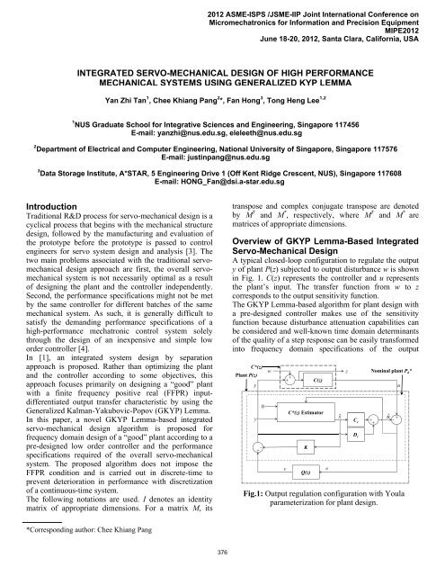
A typical closed-loop configuration to regulate the output<br />
y <strong>of</strong> plant P(z) subjected to output disturbance w is shown<br />
in Fig. 1. C(z) represents the controller and u represents<br />
the plant’s input. The transfer function from w to z<br />
corresponds to the output sensitivity function.<br />
The <strong>GKYP</strong> <strong>Lemma</strong>-based algorithm for plant design with<br />
a pre-designed controller makes use <strong>of</strong> the sensitivity<br />
function because disturbance attenuation capabilities can<br />
be considered and well-known time domain determinants<br />
<strong>of</strong> the quality <strong>of</strong> a step response can be easily transformed<br />
into frequency domain specifications <strong>of</strong> the output<br />
w<br />
z Nominal plant P0 *<br />
Plant P(z)<br />
+<br />
y u<br />
+<br />
C*(z)<br />
C(z)<br />
y<br />
+ -<br />
0<br />
v<br />
C*(z) Estimator<br />
K<br />
Q(z)<br />
Fig.1: Output regulation configuration with Youla<br />
parameterization for plant design.<br />
e<br />
ˆx<br />
C c<br />
D c<br />
+ +<br />
û<br />
+<br />
-
sensitivity function [5]. The following lemma shows the<br />
application <strong>of</strong> the <strong>GKYP</strong> <strong>Lemma</strong> to the loop shaping <strong>of</strong><br />
the discrete-time sensitivity function [2].<br />
<strong>Lemma</strong> 1: Given sensitivity function S(z) = CS(zI-AS) -1 BS<br />
+DS with AS being stable. |S(e j )| r over a finite<br />
frequency range for a given scalar r > 0 if<br />
and only if there exist Hermitian matrices P and V 0<br />
such that<br />
* *<br />
A B 0 0<br />
S S A B S S C S<br />
*<br />
I 0<br />
<br />
I 0<br />
<br />
0 I<br />
<br />
D 0,<br />
S <br />
C D S S<br />
I <br />
<br />
where = -r 2 , = -1, and<br />
<br />
(1)<br />
P V<br />
<br />
*<br />
V P2cosRV .<br />
(2)<br />
<br />
Applying Schur’s complement to (1), = -r and = -r,<br />
and r becomes a variable to be optimized. In (2), the<br />
values <strong>of</strong> scalars R and depend on the frequency range<br />
considered and are shown in Table 1.<br />
Table 1: R and for Different Frequency Range<br />
l<br />
h<br />
l h<br />
R l ( )/ 2<br />
h l<br />
h <br />
1 j ( l h)/2<br />
<br />
e<br />
However, the plant design parameters are to be restricted<br />
to CS and DS <strong>of</strong> (1). To overcome this, Youla<br />
parameterization is required. The Youla parameterization<br />
for plant design is shown in Fig. 1. Its details will be<br />
explained along with the presentation <strong>of</strong> the steps for the<br />
proposed integrated servo-mechanical design algorithm in<br />
the next section.<br />
Design Algorithm<br />
Step 1: Design a low order controller C(z) with state<br />
space matrices denoted as (Ac, Bc, Cc, Dc) to compensate<br />
for the desired low frequency characteristics <strong>of</strong> the plant.<br />
Step 2: Compute the gain matrix L <strong>of</strong> C*(z) Estimator<br />
and feedback gain matrix K using MATLAB commands<br />
given by L = Acdlqe(Ac, Bc, Cc, I, I) and K = dlqr(Ac, Bc,<br />
Cc T Cc, I), respectively. C*(z) Estimator is an estimate <strong>of</strong><br />
C*(z) with w set to zero.<br />
Step 3: Formulate the equations given by<br />
-1<br />
377<br />
x A B<br />
Kx B B w <br />
<br />
k1c c k c c k<br />
,<br />
xˆ <br />
LC A<br />
<br />
xˆ <br />
LD B<br />
<br />
v<br />
<br />
k1 c E k c c k (3)<br />
z 0 1 1<br />
k Kxk<br />
wk ,<br />
e<br />
<br />
C C<br />
<br />
xˆ <br />
D 0<br />
<br />
v<br />
<br />
k c c k c k (4)<br />
where AE = Ac – BcK - LCc, and xk refers to the value <strong>of</strong> x<br />
at discrete time k. (3-4) denote the state space<br />
representation for the combination <strong>of</strong> C*(z) with the<br />
nominal plant P0*(z), and the inclusion <strong>of</strong> e and v.<br />
Step 4: Design Q(z) as an m th order Finite Impulse<br />
Response (FIR) filter given by<br />
0 A q <br />
0 I 0<br />
m1<br />
<br />
, B ,<br />
q<br />
0<br />
<br />
1<br />
<br />
(5)<br />
C q q ... q , D q , (6)<br />
<br />
q m m1 1 q 0<br />
where q is a vector <strong>of</strong> design parameters. Set q0 to zero so<br />
that the designed plant will not have direct feedthrough.<br />
Step 5: Let Twz represent the transfer function from w to z<br />
and obtain the state space matrices <strong>of</strong> the sensitivity<br />
function S = Twz + TvzQTwe given by<br />
Awz <br />
A 0 S <br />
<br />
0<br />
0<br />
At BC q t<br />
0 Bwz<br />
<br />
0<br />
<br />
, B B ,<br />
S t <br />
(7)<br />
A BD q q t<br />
CS Cwz D C q t C , q <br />
DS D D<br />
D , (8)<br />
wz q t<br />
where (Awz, Bwz, Cwz, Dwz) and (At, Bt, Ct, Dt) denote the<br />
state space matrices <strong>of</strong> Twz and TvzTwe , respectively.<br />
Step 6: Specify i constraints on the sensitivity function<br />
using i LMIs in the form <strong>of</strong> (1) to obtain values for the<br />
vector q.<br />
Step 7: Obtain state space matrices <strong>of</strong> the plant given by<br />
A<br />
p<br />
A LD K B C LDC<br />
E c c q c q<br />
<br />
BDKBCABDC ,<br />
(9)<br />
q c q c q q c q <br />
T<br />
B , , .<br />
p L B C K<br />
q C D D<br />
p q (10)<br />
p q<br />
Simulation Example<br />
In this section, the proposed integrated servo-mechanical<br />
design algorithm is applied to the design <strong>of</strong> a highperformance<br />
mechatronic system.<br />
Lead (Pb) Zirconate (Zr) Titanate (Ti) is a piezoelectric<br />
material commonly known as PZT. The frequency<br />
response <strong>of</strong> a PZT microactuator from a commercial 3.5”
Magnitude (dB)<br />
Phase (deg)<br />
Magnitude (dB)<br />
80<br />
60<br />
40<br />
20<br />
0<br />
-20<br />
180<br />
90<br />
0<br />
-90<br />
10 1<br />
-180<br />
10<br />
0<br />
-10<br />
-20<br />
-30<br />
-40<br />
10 1<br />
-50<br />
10 2<br />
10 2<br />
Frequency (Hz)<br />
10 3<br />
10 3<br />
Frequency (Hz)<br />
Original Plant<br />
Nominal Plant<br />
Designed Plant<br />
Lag Compensator<br />
Open Loop<br />
Fig.2: Bode plots <strong>of</strong> original plant, nominal plant,<br />
designed plant, lag compensator and open loop.<br />
Closed-loop w ith Nominal Plant<br />
Closed-loop w ith Designed Plant<br />
Fig.3: Comparison <strong>of</strong> sensitivity functions.<br />
dual-stage Hard Disk Drive (HDD) is measured and<br />
modeled as having two main high frequency resonant<br />
modes at 4.70 kHz and 13.5 kHz. A discrete-time first<br />
order lag compensator with a sampling frequency Fs <strong>of</strong> 40<br />
kHz is designed to produce an open loop bandwidth <strong>of</strong> 2<br />
kHz with the original plant. The Bode plots <strong>of</strong> the original<br />
plant model and the lag compensator are shown in Fig. 2.<br />
As the closed-loop system is unstable due to the 4.7 kHz<br />
resonant mode, the proposed algorithm is used to redesign<br />
the frequency response characteristics <strong>of</strong> the PZT<br />
microactuator. m is chosen to be 6, and the constraints are<br />
a) |S(f1)| -22 dB, 4.68 kHz f1 4.72 kHz,<br />
b) |S(f2)| -3 dB, 12.8 kHz f2 14.2 kHz,<br />
c) |S(f3)| r3, f3 2.6 kHz,<br />
d) |S(f4)| r4, 9.00 kHz f4 9.20 kHz, and<br />
e) |S(f5)| r5, 17.0 kHz f5 20.0 kHz,<br />
10 4<br />
10 4<br />
378<br />
where fi = iFs/2, and r3,4,5 are variables to be minimized.<br />
Constraints (a-b) shape the plant’s resonant modes so that<br />
noise and disturbances in those regions are attenuated by<br />
the closed-loop system, constraint (c) changes the closedloop<br />
bandwidth, and constraints (d-e) limit the sensitivity<br />
function’s gain beyond its 0 dB cross-over frequency.<br />
The sensitivity function <strong>of</strong> the closed-loop system with<br />
the designed plant is shown in Fig. 3. It is shaped from<br />
the sensitivity function <strong>of</strong> the closed-loop system with the<br />
nominal plant according to the constraints specified.<br />
The Bode plots <strong>of</strong> the first-order nominal plant and<br />
seventh-order designed plant are shown in Fig. 2. A high<br />
order plant is not an issue unlike a high order controller.<br />
The first resonant mode <strong>of</strong> the designed plant at 4.70 kHz<br />
has a phase <strong>of</strong> 3.46º while the second resonant mode at<br />
13.5 kHz has a phase <strong>of</strong> -363.67º. The Bode plot <strong>of</strong> the<br />
resulting open loop is also shown in Fig. 2. The open loop<br />
bandwidth is 1.5 kHz and its phase margin is 94º. The<br />
drop in bandwidth is due to zeros in that region. Finally,<br />
the resonant modes are phase stabilized [4] by the lag<br />
compensator despite being out-<strong>of</strong>-phase.<br />
Conclusion<br />
In this paper, a <strong>GKYP</strong> <strong>Lemma</strong>-based integrated servomechanical<br />
design algorithm has been proposed. The<br />
algorithm yields a plant design that can meet the<br />
performance specifications <strong>of</strong> the overall servomechanical<br />
system with a low order controller through<br />
loop shaping <strong>of</strong> the sensitivity function. Our future work<br />
includes the consideration <strong>of</strong> plant parameter pertubations<br />
in the design algorithm. With such a modification, a set <strong>of</strong><br />
plant designs that can meet the required closed-loop<br />
performance specifications with a low order controller<br />
will be obtained.<br />
References<br />
[1] T. Iwasaki, 1999, “<strong>Integrated</strong> System Design by<br />
Separation,” in Proceedings <strong>of</strong> the IEEE International<br />
Conference on Control Applications, 97-102.<br />
[2] T. Iwasaki and S. Hara, 2005, “Generalized KYP<br />
<strong>Lemma</strong>: Unified Frequency Domain Inequalities with<br />
Design Applications,” IEEE Trans. on Automatic<br />
Control, 50:41-59.<br />
[3] C. K. Pang, F. L. Lewis, T. H. Lee, and Z. Y. Dong,<br />
2011, Intelligent Diagnosis and Prognosis <strong>of</strong> Industrial<br />
Networked Systems, CRC Press, Taylor and Francis<br />
Group, Boca Raton, FL, USA.<br />
[4] T. Yamaguchi, M. Hirata, and C. K. Pang (eds.),<br />
2011, High-Speed Precision Motion Control. CRC press,<br />
Taylor and Francis Group, Boca Raton, FL, USA.<br />
[5] K. Zhou, J. C. Doyle, 1996, Essentials <strong>of</strong> Robust<br />
Control. Prentice Hall, New Jersey, USA.