Aux Positioner Lecture Notes
Aux Positioner Lecture Notes
Aux Positioner Lecture Notes

Create successful ePaper yourself
Turn your PDF publications into a flip-book with our unique Google optimized e-Paper software.
<strong>Aux</strong>iliary positioner.<br />
<strong>Lecture</strong>s<br />
.!i
1.<br />
2.<br />
3.<br />
lntroduction<br />
Contents<br />
Purpose, the block diagram and a principle of article operation<br />
3<br />
1.1. Purpose and the basic characteristics of the auxiliary positioner<br />
1.2. Block diagram of the positioner control system<br />
'1.3. Modes of AP functioning<br />
The positioner description<br />
2.1. <strong>Positioner</strong> design<br />
Construction and operation of the positioner mechanical components<br />
3.1. Abearingarm<br />
3.2. The flange<br />
3.3. Landing ring<br />
3.4. Electromechanical azimuth drive<br />
3.5. Electromechanical drive of the elevation axis<br />
3.6. Angulartransducers<br />
3.7. Instrumentation<br />
3.8. Radome fastening<br />
4. The positioner control sYstem<br />
4.1. HPIB Controller<br />
4.2. The arithmetic-logic unit<br />
4.3. Power amplifier<br />
4.4. <strong>Positioner</strong>angularcoordinate transducers<br />
23<br />
4.5. Control sYstem Power unit<br />
5. Operation and servicing of the positioner<br />
5.1. Preparation for mounting and mounting.<br />
5.2. Preparation for oPeration<br />
5.3. Coordinate transducers alignment<br />
5.4. Maintenance service of the positioner<br />
5.5. <strong>Positioner</strong> malfunctions and their elimination<br />
5.5.1. Mechanical units malfunction<br />
5.5.2. Control system malfunction<br />
3<br />
4<br />
5<br />
6<br />
6<br />
10<br />
10<br />
10<br />
10<br />
10<br />
13<br />
14<br />
15<br />
15<br />
16<br />
16<br />
1B<br />
22<br />
24<br />
25<br />
25<br />
25<br />
25<br />
26<br />
27<br />
27<br />
28
Introduction<br />
the Present description is intended for studying a design, a principle of action and<br />
characteristics of the positioner. lt is necessary for full and correct use of technical<br />
capacities of the article. The description consists of the following basic sections:<br />
"lntroduction".<br />
1. Purpose .<br />
2. The positioner description.<br />
3. Construction and operation of the positioner mechanical components.<br />
4. The positioner control system.<br />
5. Operation and servicing of the positioner.<br />
1. Purpose, the block diagram and a principle of article operation.<br />
The article further called the auxiliary positioner (AP) is intended for spatial orien-<br />
tation of the object under test placed on it in order to study its radio characteristics. The<br />
positioner enters into the complete set of the pedestal positioner-2 (PP-2) and consid-<br />
erably expands its technical capacities. Operation of the article is carried out in the<br />
closed, specially equipped room at an ambient temperature no more +33C, relative hu-<br />
midity no more 90%, at temperature 20C.<br />
1.1 Purpose and the basic characteristics of the auxiliary positioner.<br />
AP is fixed on a faceplate of polarization axis of PP-2. The positioner is intended for the<br />
measurement of antenna parameters. lts characteristics are the follows:<br />
1) Quantity of controlled coordinates.:...':.:...:..'.'.... .......2<br />
2) Range of moving:<br />
- azimuth coordinate ....!45 1,,.<br />
-<br />
- elevation coordinate .. ... ...t45 l<br />
3) the Maximal speed of movement, deg/sec... .<br />
4) Number of the fixed speeds of movement, ,. ,.. . ! ,r )<br />
5) Numberof digits of digital transducers .........15<br />
6) Error of positioning, angular sec. . ... ... ... .40<br />
7) Power supply
-frequency, Hz. .. 5011<br />
-voltage, V.............. .....220t10%<br />
8) Power consumption, W. ... . no more than 300 ,.,r<br />
9) Carrying capacity, k9... .......S0..<br />
2.1.3. Structure of the article.<br />
The auxiliary positioner consists of the mechanical part and control system. The<br />
control system is a rack connected with the manual control unit by cables. The me-<br />
chanical part is connected with the control system rack by cabres.<br />
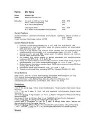
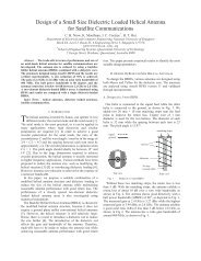
1.2 Block diagram of the positioner control system.<br />
. The positioner control system is a follow-up control system with two negative feed-<br />
backs: position feedback - for maintenance of positioning of drives with required accu-<br />
racy, and velocity feedback - for maintenance of a constancy of speed of rotation of<br />
drive motors while movement. The block diagram of the AP control system is presented<br />
in Fig. 1. The AP control system consists of Hlg controller, arithmetic-logic unit, man-<br />
ual-control unit, and two channels of the movement control by azimuth and elevation.<br />
x16 X16<br />
,{l<br />
Fig I Coneecwn d'ag,an<br />
AI - Conlrol syslen<br />
A2 - Distributtion ba\<br />
A3 - Manual @nlrcl unil<br />
A4 -<strong>Aux</strong>iliaty posiliml<br />
K|- Cable<br />
K2 - Cable MCU<br />
K3 - Dislibution able<br />
Each channel of the movement control consists of the power amplifier (PA), the motor<br />
(M) and tachometer (TM), what is a velocity feedback. The power amplifier includes the<br />
velocity former (VF), the speed controller consisting of the subtractor and pulse-width<br />
modulator (PWM) with a protection device. The motor is connected to the PWM output.<br />
The tachometer (TM) is the velocity-feedback transducer. The angle rotation transducer<br />
is connected to output motor shaft by means of mechanical transition. This transducer
is a position feedback transducer.<br />
The commands coming from the control computer (CC) by HPIB interface are decoded<br />
by the controller. According to parameters of the accepted command the data for the<br />
task formation at the ALU output are sent to the ALU. Then the task is transferred to the<br />
velocity former (VF) of PA of the corresponding coordinate. ,<br />
. Depending on the current value of coordinate and required speed of movement,<br />
the velocity task is formed at the VF output. Then the task is sent to the subtractor input.<br />
The velocity feedback signal from the tachometer output comes to another subtractor<br />
port. The velocity error signal from the subtractor output comes to FWfrrf *iliit'r-'Jontrots<br />
the work of the motor. Presence of the velocity feedback provides rotation of a corre-<br />
sponding axis with the constant speed. During movement continuous interrogation is<br />
made of the current coordinate value. lf the required final value of angle is attained, the<br />
signal for the motor stopping is formed at the ALU output.<br />
1.3 Modes of AP functioning.<br />
The positioner operates in two modes: manual and automatic. The manual mode<br />
is intended for check of the positioner serviceability during preventive maintenance, and<br />
also for determination of its characteristics at certification. The positioner movement by<br />
each coordinate is controlled from the manual control unit (MCU) or by means of the<br />
controls located on the ALU front panel,<br />
The automatic operating mode is the basic one at carrying out of measurements<br />
with the help of the measuring complex, thus the positioner is controlled from the com-<br />
puter by HPIB interface. Control commands are presented in the Annex 1 of the De-<br />
scription.
2. The positioner description.<br />
The positioner is an assembly of a mechanical construction with angular transducers<br />
and the motors which are set on a faceplate of the PP-2 polarization axis and control<br />
system (CS) connected with the control computer by HPIB interface. The equipment<br />
placed on a mechanical construction is connected to the CC output connectors by ca-<br />
bles dressed in metal.<br />
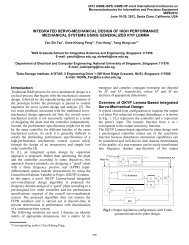
2.1 <strong>Positioner</strong> design.<br />
<strong>Positioner</strong> construction and operation.<br />
Fig.2<br />
elevation<br />
/-745'<br />
4<br />
rJ<br />
The positioner construction contains the following basic elements represented in Fig. 2<br />
and 3:<br />
pola::ization<br />
- bearing arm (BA). .............. 1<br />
- azimuth drive (AD) ...... B<br />
elevation drive (ED)... ................... 10<br />
-flange. .......11<br />
- landing ring . . ... ...29<br />
- angular transducers... .. .. ...2 and 9<br />
6
<strong>Aux</strong> positioner structure.<br />
The bearing arm 1 is fastened on the flange 11 by bolts. The AP body 8 is set in<br />
bearings on the bearing arm 1 (Fig. 2). ln turn, the body 8 of the azimuth drive is articu-<br />
lated by means of the lever4 and the sliding member 15 with the ED output shaft 16.<br />
The landing ring 29 for the installation 110 (Fig. 3) is fastened on arms 5 and 7 con-<br />
nected to the azimuth drive output shaft 18.<br />
7
k)l<br />
*N.<br />
3\\'<br />
L\<br />
"\,1 ,tt \4-<br />
41L// ,/ z ,/<br />
-.t' tt'<br />
"L -". / ,ao;,<br />
t./<br />
-.t.-<br />
F\V<br />
'r/ rl<br />
___,.-]----<br />
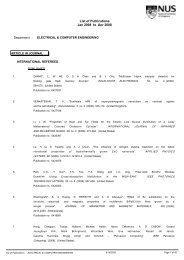
Fig.3<br />
I \- IJ<br />
r)<br />
\ /c<br />
-'F $
L Bearinq arm<br />
2 Anqle transducer<br />
3 Brake devi ce<br />
4 Lever<br />
5 Arm (brackec )<br />
6 Azirnuth drive electric motor<br />
7 Arm (bracket)<br />
B Body<br />
9 Azlmuch anqfe rransducer<br />
l0 Elevation drive<br />
L 1 Flange<br />
L2 bearinq<br />
L3 bearinq<br />
I4 bearinq<br />
l5 Slider<br />
L 6 Shaft<br />
L1 bearinq<br />
L8 Shaft<br />
19 bearinq<br />
20 Screw<br />
2L bearinq<br />
22 Shaft<br />
23 Flexible wheef<br />
24 Wave qenera!or<br />
25 Rinq<br />
26 Coqwheel<br />
21 bearinq<br />
28 movable rins<br />
29 motionless wheel<br />
30 Bushinq<br />
31 beffows sfeeve<br />
32 shaft<br />
Desisnation of elements in Fis. 2 and 3<br />
33 bearinq<br />
34 plate<br />
35 bearinq<br />
3 6 rotor<br />
31 stator<br />
38 screw<br />
3 9 bodr,<br />
40 Bushins<br />
4L worm sector<br />
42 worm screw<br />
43 bodv<br />
44 bearinq<br />
45 qear<br />
46 bearino<br />
41 gear<br />
4 8 sear<br />
49 gear<br />
50 bearing<br />
51 qrnnor- nl:--g<br />
\2 Shall /cl:qql<br />
53 qear<br />
54 wheef<br />
55 bearinq<br />
5 6 gear<br />
51 bearins<br />
58 qear<br />
59 radome fasteninq device<br />
60 bracket<br />
6 1 bracket<br />
62 screw<br />
63 clamp<br />
Moving of the positioner components in the assigned range is limited by the end<br />
switches. The operation of the positioner electromechanical systems is adjusted with<br />
the help of control system (CC) (not shown in Fig. 2 and 3).<br />
The positioner operates as follows. With control signals coming, the output ele-<br />
ments of drives namely shafts 18 and 16 correspondingly begin rotation in the specified<br />
direction and specified mode. lt is provided with presence of transducers of position<br />
feedback 2 and 9 and by velocity. The last ones are the tachometers placed on elec-<br />
tric motors 6 and 9. In so doing the change of angular position of AD body 8 by means<br />
of the lever4, the sliding member 15, arms 5 and 7 in appropriate way changes the an-<br />
gular position of the landing ring 29 with the target.<br />
9
3. Construction and operation of the positioner mechanical components.<br />
3.1. A bearing arm.<br />
The bearing arm (BA) 1 is a base element of the positioner. On the one hand BA<br />
has a setting plate by means of which it is based on flange 11, on the other hand, it is<br />
finished by a plug with landing holes for the setting of the body AD 8in the bearing sup-<br />
ports.. In the BA 1 middle part the guide for the sliding member 15 and a support for the<br />
bearing 44 are executed.<br />
3.2. The flange<br />
The Flange 11 (Fig. 2) is an assembly unit and is intended for the placement of<br />
elements of the positioner construction and its setting on 23 of PP-2 (see description of<br />
PP-2, Fig.2).<br />
It consists of a supporting plate 51 (Fig. 3) with the holes for the fastening by<br />
means of bolts to the faceplate of PP-2 and a glass 52 with an external landing surface<br />
for the exact installation of the positioner with respect to the polarization axis on the<br />
faceplate of PP-2. Simultaneously the flange serves as the elevation drive body.<br />
3.3. Landing ring.<br />
The landing ring is intended for the installation of researched object. lt consists<br />
of a stationary ring 28 which is fastened to arms 5 and 7 by bolts and a movable ring 29<br />
which is set on the stationary ring 28 using threaded joint. Fixing of the movable ring<br />
with respect to the stationary ring is carried out by 2 bolts 20. The scale for readout of<br />
the ring angle of rotation is put on the lateral surface of movable ring 29 (Fig. 3).<br />
3.4. Electromechanical azimuth drive.<br />
The drive 8 (Fig. 2) is intended for the movement of the auxiliary positioner with respect<br />
to the azimuth axis. The drive construction consists of the direct-current motor 6 with<br />
the inserted tachometer, position transducer BT-72 9, electromagnetic brake device 3<br />
for the object fixation in the specified position, and three-step reducer.<br />
The drive and its elements have the following characteristics:<br />
:<br />
- the maximal possible torque, Nm...... ........ 978.8<br />
- the maximal angular speed of an output member, rev/min. ..... 1,02<br />
10
- the general reducer gear-ratio,.,,..... ,....3899<br />
- accuracy of positioning, sec. ...-40<br />
Electric motor:<br />
- type........ [n60-90-4-24P09[09 (Russian specification)<br />
- voltage, V....... ...............24<br />
- the maximal number of revolutions. Rev/min.. ..... 4000<br />
- the nominal torque, Nm, .0.2150<br />
Electromagnet:<br />
- voltage, V....... ............24<br />
- developed axial force. N.............. .........25<br />
The drive is represented in Fig. 3 and its structure is the follows. The target shaft<br />
18 is set in the body B on bearings 17 and 19. The shaft 18 is rigidly connected by one<br />
end to an arm 5 and by another end it is connected to a flexible wheel 23. Bearings 21<br />
and 27 are placed on the shaft 18 and in the body detail 30. The gear wheel 26 with the<br />
generator of waves 24 of the wave transition is set in bearings 21 and 27. The wave<br />
transition consists of a ring 25 with the internal gearing, set in the body 8 and the flexi-<br />
ble wheel 23 rigidly connected with the output shaft 18.The gearing wheel 26 (Fig.4) is<br />
kinematically connected with the eclectic motor 6, gear elements 53, 54, and 56. In so<br />
doing the gear 53 is set on the shaft of the motor 6/ the wheel 54 and the gear 56 are in<br />
the bearings 55 and 57.<br />
11
Fig.4<br />
The brake device (Fig. 5) consists of the body 1 with the induction coil 8. The<br />
first brake disk 3 is set inside of the body. lts rotation is restricted by a pin 2 and it com-<br />
municates with a spring 6 through a pusher 7, the effort of the spring is controlled by the<br />
screw 9. The second brake disk 4 is rigidly fixed on the shaft 5. On the other end of a<br />
shaft 5 the gear 56 is set. lt is in gearing with a wheel 54. The shaft 22 (Fig.2) of the<br />
gearing wheel 26 is connected to the shaft 32 of the elevation transducer 9 by the bel-<br />
lows clutch 31.<br />
The drive works as follows. Without control signal, the disk 3 under the influence<br />
of the spring 6 is in power contact to the disk 4 that provides the fixation of the gearing<br />
wheel 26 (Fig. 4). With a signal to start movement, the current is applied to the winding<br />
of the induction coil 8 of the brake device. In so doing the disk 3 moves and com-<br />
pressed the spring 6 and releases the disk 4 (Fig. 5).<br />
T2
I<br />
Fig.5<br />
2). The torque from the electric motor 6 is transferred to a target shaft 18 (Fig.<br />
2,3) by the kinematical circuit including elements 53,54,56, 26.25,24, and 23. lt pro-<br />
vides the movement of the arm 5 and 7 with a landing ring 29.<br />
The specified angular position is provided with the position transducer 9 which is<br />
set on the body of a reducer 8 and is rigidly connected to the shaft 22 of the gearing<br />
wheel 26 (Fig. 3).<br />
3.5. Electromechanical drive of the elevation axis.<br />
Drive 10 (Fig. 2) is assigned for the movement of the body of the reducer 8 of<br />
the azimuth drives. Thus moving of a landing ring 29 with AP with respect to the eleva-<br />
tion axis is attained (Fig. 3).<br />
The drive and its elements have the following characteristics:<br />
:<br />
- maximal torque of the output shaft, Nm.... ... 4,59<br />
- reducer gear-ratio ..... 18.2<br />
- accuracy of positioning, sec. ........40 "<br />
Electric motor:<br />
- type ....... An60-90-4-24P09809<br />
I<br />
(Russian specification)<br />
- voltage, V............. .....24<br />
- the maximal number of resolutions. Rev/min. .... 4000<br />
I3
- the nominal torque, Nm.... 0.2150<br />
Structurally the drive consists of the electric motor 10, a two-level cylindrical re-<br />
ducer which body is the flange 11, screw - nut transition with the lever 4, hingedly con-<br />
nected to the AD body 8 (Fig. 3), and the transducer of angular position 2 (Fig. 2). The<br />
output shaft 16 executed as a screw, is set in bearings 12,13, 14, and 44 on the bear-<br />
ing arm and the flange 1 1. lt is kinematically connected with slider 15 forming the screw-<br />
nut transition. The slider 15 is restricted from the rotation and by one side moves along<br />
the base guide. The output shaft 16 is kinematically connected to the electric motor 10<br />
through the two-step cylindrical reducer consisting of gear elements 45,47,48,49 set in<br />
bearings 46,50. The transducer of the angular position 2 is placed in the body which<br />
construction is unified for all drives.<br />
The drive works as follows. According to the CC command the torque from the<br />
electric motor 10 is transferred bythe kinematical circuit including elements 49,45,48,<br />
47,16,15and4. ltprovides movementinthespecifieddirectionandwiththespecified<br />
speed of the body of reducer B of azimuth drive. It allows making the object under test<br />
moving with respect to the elevation axes.<br />
With set position attained by the slave unit of the drive, what is fixed by angular<br />
transducer 2, the motor 10 is disconnected.<br />
3.6. Angular transducers.<br />
. Angular transducers (AT) 2 and 9 (Fig. 2-3) provide the movement feedback<br />
with respect to azimuth and elevation axes. All transducers have the built - in rotating<br />
transformer BT -71 (Russian abbreviation) in the base.<br />
. The construction of the angular transducers is based on the bearing body 39, in the<br />
boring of which the bushing 40 is disposed. The stator 37BT (Russian abbreviation) is<br />
placed on the bushing 40. The bushing 40 is fastened to the body 39 by screws 38.<br />
The angular movement is possible within the limits of grooves. The rotor 36 BT (Rus-<br />
sian abbreviation) is fixed on the output shaft 32 with the help of plates 34 and rotates in<br />
bearings 33 and 35, which are placed in boring of the body 39.<br />
Worm sector 41 is rigidly connected to the bushing 40. lt communicates with a<br />
worm 42 set in the body 43, rigidly connected with the bearing body 39. The worm pair<br />
41 and 42 is intended for setting of "zero" of the transducer which is carried out as fol-<br />
lows.<br />
To coordinate initial "zero" position of the positioner executive elements and AG<br />
indications it is necessary to remove a cover and to weaken screws 38 up to make pos-<br />
sible free rotation of the bushing 40 with stator 37 with respect to the body 39. Rotating<br />
T4
the worm 42 one should attain the angular position of the stator 37 with respect to the<br />
stationary rotor 36 which corresponds to "zero" position of BT-71. After that the bushing<br />
40 should be fixed by screws 38 and set the cover.<br />
3.7. Instrumentation.<br />
The following instrumentations enter the structure of the given article:<br />
angular movement transducers .,, ,,... Rotating transformers BT-71<br />
speed transducers ............ built - in tachometers of electric motor<br />
In60-90- 4-24P 09 809 (Russian specification)<br />
Basic specifications and characteristics of instrumentations are presented in certificates.<br />
3.8.Radome fastening.<br />
The device for radome fastening is set on the flange 11. lt consists of 4 bearing<br />
arms. Each bearing arm has two height- and length-controlled bearing arms 60 and 61.<br />
To fix the radome on the fastening device the screw 62 with movable clamp 63 is used,<br />
In addition, the positioner is supplied with radome fastening device.<br />
15
4. The positioner control system<br />
The control system (CS) is the block in which control unit and power supply unit<br />
are disposed.<br />
The connectors are disposed on the unit rear panel. They are used to connect<br />
the positioner drives and transducers to the control system by cables.<br />
Schematic electric diagrams of cables and AP are presented in the Annex.<br />
The control system consists of the following units: HPIB controller, the arithme-<br />
tic-logical unit, two blocks of transformation of the output signals of angular transducers<br />
(phase-code transformer - PCT) and two power amplifiers. Transducers of the input al-<br />
ternating voltage to direct current voltage are located in the power unit. Schematic elec-<br />
tric diagrams of control system units connections are presented in Annex (400.01.12 )<br />
4.1 HPIB Controller.<br />
HPIB controller is used to provide the communication between the control com-<br />
puter and the positioner control system through HPIB interface.<br />
The controller provides reception of control commands of a corresponding for-<br />
mat, decoding of commands, transformation of data, formation of control signals and<br />
data transmission to control systems, control algorithm realization by positioner accord-<br />
ing to the accepted commands, reading of the information from transducers of control<br />
systems and transfer of the received information to the control computer The controller<br />
realizes the following HPIB interface functions determined by standard IEEE-488:<br />
1. Source Handshake 1(SHl);<br />
2. Acceptor handshake 1 (AH1);<br />
3. Listener (13);<br />
4. Talker (T5);<br />
5. Service request 1 (SR1);<br />
6. Device clear (DC1).<br />
In so doing the following interface messages are processed:<br />
1. Talker address (TAD);<br />
2. Listener address (LAD);<br />
3. Serial poll enable (SPE);<br />
4. Serial poll disable (SPD);<br />
5. Device clear (DCL);<br />
16
6. Selected device clear (SDC);<br />
7 Unlisten (UNL).<br />
The Controller is a microprocessor device that operates according the code writ-<br />
ten in ROM. The electric schematic circuit of the controller is shown in the Annex 2-1.<br />
With power switched on, the initialization of the controller is realized according to<br />
the program which includes the reading of the address setter on switches and indication<br />
of the address of the HPIB bus controller on the front panel, programming of a microcir-<br />
cuit of the HPIB interface controller and processor timers, an output of signals "Stop" to<br />
the drive motors. Then the controller turns to the standby mode waiting for the com-<br />
mands from the control computer.<br />
The commands accepted by HPIB interface are decoded by the required algo-<br />
rithm of the control system processor operation is realized according to the program.<br />
Data exchange by HPIB bus is realized according to HPIB report at a hardware level of<br />
the interface microcircuit. HPIB controller commands allow realizing the following posi-<br />
tioner functions:<br />
1) installation of coordinates of the positioner drives in any position from the<br />
specified angular range;<br />
2) scanning of coordinates with simultaneous measurement in the set points.<br />
Movement can be carried out with one of four preset speeds Trajectory of scanning are<br />
the following: linear nine-by-line with change of the movement direction by azimuth and<br />
elevation axes,<br />
3) measurement of the current values of all coordinates. lt is carried out by<br />
means of a special command according to which the controller polls all coordinate<br />
transducers and forms the target buffer in HPIB symbolic-coding format. With control-<br />
ler addressed to transition the controller transfers the measured values to the computer.<br />
The description of commands of controller computer are presented in the Annex 1-2.<br />
With operation of the controller, its status is fixed in the status byte which is dis-<br />
played on the controller front panel and the computer can read out the data in the proc-<br />
ess of serial poll. With error situations during controller RAM operation, the error type<br />
and its code is written into the special error stack organized according to the LIFO prin-<br />
ciple. The error type is simultaneously written in the status byte. Each bit of the status<br />
byte may cause inquiry on service, but can be disguised by a special control command<br />
from the control computer. Error reading is also realized by means of a special com-<br />
mand.<br />
T7
the Annex .<br />
The description of the controller message codes of and errors are presented in<br />
At measurements in the scanning mode with measuring equipment starting di-<br />
rectly from control system the "START" signals are formed on the controller plate by<br />
special former controlled by the controller processor. Duration of a pulse is soft defined<br />
and is equal to 7 mcs. Polarity of pulses is positive.<br />
4.2 The arithmetic-logic unit.<br />
Arithmetic-logic unit (ALU) is intended for the calculation of 16-digit binary code<br />
(in view of a sign) of a difference between the task for movement and the value of a<br />
code of the feedback transducer. The code of the transducer is read out from PCT. The<br />
received code of the difference for each coordinate (azimuth or elevation) is sent to the<br />
power amplifiers, which are carrying out drives control.<br />
ALU has two operating modes:<br />
- Automatic control;<br />
-Manual control.<br />
ln automatic operating mode ALU calculates the difference for each of coordi-<br />
nates by multiplexing in time of the moments of the information processing, which are<br />
determined by the control signals former. The task for movement and movement control<br />
(Start / stop) by each coordinate is carried out by the HPIB controller (CHPIB) according<br />
to the commands received from the control computer and algorithms of the control sys-<br />
tem functioning.<br />
In a manual operating mode each coordinate control is carried out by means of<br />
the controls located on the ALU front panel, or on the manual control unit (MCU). Basic<br />
electric schematic diagram of ALU is presented in the Annex 2-2. Basic electric sche-<br />
matic diagram of MCU is presented in the Annex 2-6.<br />
Functionally ALU of the auxiliary positioner control system corresponds to the<br />
ALU of PP-1 and PP-z.<br />
The positioner control in a manual operating mode is carried out with the help of<br />
the ALU front panel. The schematic diagram of the front panel is presented in the An-<br />
nex .<br />
ALU front panel is a microprocessor controller realized on microcircuit AT89C52<br />
what is different from ALU of PP-1 and PP-2. Buttons START and STOP. the switch of<br />
operating modes, buttons of the coordinates and speeds task setting, and the toggle-<br />
switch of inclusion MCU are connected to the microprocessor. To display the value of<br />
18
the task on the chosen coordinate and a number of velocity, there are indicators on the<br />
ALU front panel.<br />
In automatic control mode the switch "MODE" is in position "HPlB". In this case<br />
the message "HPlB" is output on indicators and controls of the front panel are blocked.<br />
In manual mode (the switch "MODE" is set in positions 1,2,3) the process is controlled<br />
by only one chosen coordinate using the front panel of ALU ("Start ", "Stop").<br />
The task on the chosen coordinate is set digit-by-digit. The digit of the specified<br />
value is chosen by consecutive pressing of button "SELECT", and the value of the cho-<br />
sen digit is chosen by pressing the button "SET". Simultaneously the binary code of the<br />
task is byte-series output and it is written in memory registers of the ALU main plate.<br />
Beside that the signal of 200 KHz frequency is constantly formed at the output<br />
of the microprocessor on the front panel which necessary for operation of the ALU pulse<br />
distributer.<br />
Manual control mode is carried out with the help of MCU with switch-on of the<br />
toggle-switch on the ALU front panel or the similar toggle-switch on MCU. ln this case<br />
switch-on of drives, a choice of speed and a direction of movement is realized by MCU<br />
controls.<br />
Schematic electric diagrams of manual control unit and its cables are presented<br />
in Annex (400.01.10 ED and 400.01.15 ED)<br />
4.3 Power amplifier.<br />
The power amplifier (PA) is used to form the control voltage at the motor. The<br />
constancy of speed of the drive rotation is provided according to a negative velocity<br />
feedback. The signal of the feedback is formed at the tachometer output.<br />
The following elements are located on the power amplifier plate: the (VF), veloc-<br />
ity controller (VC), power-width modulator (PWM), and protection devices. The electric<br />
schematic diagram of the power amplifier is presented in Annex .<br />
Resistor (current sensor) is inserted in the bottom general point of the bridge.<br />
Voltage loss on the resistor is an input signal for the scheme of protection. With voltage<br />
increase on the resistor, the scheme of protection operates, and the motor is discon-<br />
nected. A light-emitting diode "Overload" is lit on the PA front panel. To restore service-<br />
ability of the amplifier it is necessary to remove the reason of the overload of the motor<br />
and to press button " RESET " on the PA front panel.<br />
4.4 <strong>Positioner</strong> angular coordinate transducers.<br />
Rotating transformers such as BT-71 (Russian abbreviation) with phase-code<br />
t9
transformers (PCT) serve as transducers of angular values. Signals of sine shape from<br />
PCT come to the BT-stator windings.<br />
The axis of rotor BT is mechanically connected to a corresponding positioner axis<br />
of rotation. With a turn of the BT rotor, the phase of output signals of the measuring<br />
windings located on a rotor, changes proportionally to the angle of rotation. PCT trans-<br />
forms the value of a phase into the1S-digit digital code which is delivered to the ALU da-<br />
tabase bus, general for all PCT,<br />
PCT are bought articles and their principle of action, and also the order of opera-<br />
tion is presented in the PCT Description.<br />
4.5 Control system power unit.<br />
Control system power unit is intended for the formation of the feeding voltage<br />
necessary for functioning of the control system. The basic schematic diagram of the<br />
power unit is presented in Annex.<br />
The unit is placed in the CS rack.<br />
The unit consists of the following voltage transformers:<br />
- AC/DC of 5-25-5 type for feeding of control system logic devices;<br />
- AC/DC of 5-320-24 type for feeding of motors power circuits;<br />
- DC/DC of DKE15B-15 type for feeding of operational amplifiers.<br />
Parameters of transformers are presented in Table 2<br />
Type Input voltage<br />
(v)<br />
Table 2<br />
The toggle-switch "Power supply" and indicators of feeding voltage are located<br />
on the front panel of the power unit.<br />
Output volt-<br />
age (V)<br />
Output cur-<br />
rent (A)<br />
s-25-5 AC 200-240 DC5 5<br />
s-320-24 AC 200-240 DC 24 12.5<br />
DKE15B-15 DC 18-36 DC t15 r0.500<br />
20
5 Operation and servicing of the positioner.<br />
5.1. Preparation for mounting and mounting.<br />
Articles are delivered to a place of operation knocked-down in transport package.<br />
Before assembly and installation of the article on PP-2 it is necessary to make<br />
sure of availability of positioner units in accordance with the description.<br />
Before assembly it is necessary to make sure in absence of external mechanical<br />
damages, and also to remove a layer of protective greasing from surfaces of units and<br />
details of the article. The order of positioner installation and assembly is defined by the<br />
correspond ing description,<br />
Article mounting, its movement from a place of mounting to the working zone,<br />
and also its installation in the specified position is carried out on a rail way. After the<br />
positioner assembly it is necessary to test its conformity with parameters of the techni-<br />
cal project according to the technique.<br />
5.2 Preparation for operation.<br />
<strong>Positioner</strong> preparation for work is carried out in the following sequence:<br />
- to set the auxiliary positioner on the PP-2 faceplate;<br />
- to prepare PP-2 for operation according to the instruction on PP-2;<br />
- to set and fix PP-2 by screws 28 and 50 in a working position;<br />
- to earth bodies of control systems of PP-2 and AP;<br />
- to connect the cable system PP-2 to the PP-2 control system, AP cable system<br />
to its CS and to make sure in a manual mode in execution of commands on movement<br />
by both coordinates within the limits of the set ranges, presence of feedback signals,<br />
and operation of end switches.<br />
HPIB cable.<br />
Connect auxiliary positioner control system with the control computer by the<br />
ATTENTION:<br />
1. All connections of control systems with control computer, AP, and<br />
PP-2 must be carried out when the power is switched off.<br />
2. lt is strictly prohibited to switch on the control system of AP and<br />
PP-2 when the angular transducers are disconnected!<br />
21
5.3 Coordinate transducers alignment<br />
<strong>Positioner</strong> coordinate transducers alignment is carried out on a working position<br />
in the following sequence:<br />
- connect control system to the positioner;<br />
- switch on CS and to set the manual operating mode;<br />
- serially setting value 16384 on ALU front panel for each coordinate, put coordi-<br />
nate axes in the given position;<br />
- check if this position of axes is correct ( elevation and azimuth equal to zero)<br />
by means of geodetic devices;<br />
- in case of a deviation of axes position from zero to set coordinates in zero po-<br />
sition by means of the manual control unit without changing values on ALU switches;<br />
- attain a zero mismatch on the PA indicator by means of a worm gear of the cor-<br />
responding coord inate transducer.<br />
5.4 Maintenance service of the positioner.<br />
Maintenance of positioner mechanical systems is carried out in the place of in-<br />
stallation by the maintenance personnel supervising the work of the setup and ac-<br />
quainted with the specifications on the structure and operation.<br />
In connection with design features of the positioner, repeatedly-short-term oper-<br />
ating mode of its executive mechanisms and conditions of operation, the maintenance<br />
service providing it normal functioning is carried out as preventive actions. These ac-<br />
tions include testing of absence of external mechanical damages, presence of greasing<br />
on open surfaces of executive and regulating devices' transmissions.<br />
It is necessary to control the presence of consistent greasing on surfaces of a<br />
screw gear 15 and 16 of elevation drive, guide 1, slider 5 (see <strong>Positioner</strong> description,<br />
Fig. 3). Presence of consistent greasing in closed bearing units according to conditions<br />
of delivery provides their normal functioning during all term of operation if conditions of<br />
operation are observed.<br />
It is necessary in one year of operation to replace greasing of tooth gearings of<br />
the first and second step of a reducer. In so doing complete disassembly and washing<br />
of gears are conducted. Tighten bolt and screw connections.<br />
AP control system maintenance is not required.<br />
22
5.5 <strong>Positioner</strong> malfunctions and their elimination.<br />
5.5.1 Mechanical units malfunction.<br />
Malfunctions Possible cause Way of elimination Comments<br />
Amplified noise in<br />
a reducer<br />
Motor nonuniform<br />
rotation,<br />
works with noise,<br />
overcurrent protectionperiodi-<br />
cally operates.<br />
Failure of the azi-<br />
muthal drive brake<br />
device. Motor<br />
hardly rotates.<br />
Incomplete range<br />
of moving of end<br />
switches<br />
Discrepancy of in-<br />
dications of the an-<br />
gle transducer and<br />
Wave generator,<br />
flexible wheel of<br />
wave transmission<br />
is disabled<br />
1. Significant me-<br />
chanical resistance<br />
in kinematic circuit<br />
a)absence of lubri-<br />
cant;<br />
b) presence of dirt;<br />
c) bearing disabled<br />
2. Braking device<br />
malfunction<br />
Excessive preliminary<br />
tightness of<br />
the brake spring.<br />
Wrong installation<br />
of end switches.<br />
Discrepancy of set-<br />
ting of "zero" position<br />
of the angle<br />
Replace wave<br />
transmission<br />
l.Rearrange drive<br />
kinematic circuits<br />
2. Set the gap no<br />
less 0.5 mm be-<br />
liminary tightness of<br />
spring 6, thus to<br />
unscrew the screw<br />
9 by 1,0-1,5 revolu-<br />
tions and to fix it by<br />
counternut<br />
iee positioner ser-<br />
vicing<br />
See positioner ser-<br />
vicing<br />
See positioner ser-<br />
vicing, Fig.4<br />
tween disks 3 and 4<br />
To reduce a pre- See positioner ser-<br />
To make adjust-<br />
ment of a range of<br />
operation of end<br />
switches<br />
To carry out setting<br />
of "zero" of the<br />
transducer<br />
vicing, Fig. 4<br />
iee positioner ser-<br />
vicing,<br />
ZJ
the angular position<br />
of the corresponding<br />
positioner ele-<br />
ment<br />
. Motor rotates at<br />
small and average<br />
speeds, adjustment<br />
of speed is not real-<br />
ized.<br />
Rotation of mobile<br />
landing ring 29 with<br />
respect to mo-<br />
tionless ring 28 is<br />
difficult<br />
transducer<br />
1 Pollution of ta-<br />
chometer collector<br />
or the motor<br />
2. The pulsation of<br />
tachometer target<br />
signal exceeds al-<br />
lowed values<br />
Mechanical dam-<br />
ages of groove,<br />
incomplete fixing of<br />
rings by bolts 20,<br />
pollution of a<br />
groove ls compli-<br />
cated, absence of<br />
greasing<br />
5.5.2 Control system malfunction.<br />
1. To clear<br />
collectors of a dust,<br />
to wash out by<br />
gasoline or spirit<br />
2. To replace<br />
the motor with ta-<br />
chometer<br />
Remove failure,<br />
unscrew bolts 20,<br />
To clear screw joint<br />
of a dust, to grease<br />
it.<br />
lee positioner ser-<br />
vicing, Fig.2<br />
Malfunction Possible cause elimination comment<br />
At any command 1) electronic protection ol To do away the arisen<br />
and any mode the the target cascade has reason of an overload:<br />
motor does not ro-<br />
tate, the mismatch is<br />
displayed.<br />
operated<br />
2) Malfunction of ele-<br />
ments of the permission<br />
signals former<br />
3) chip of power amplifier<br />
output cascade ls plate<br />
faulty<br />
presence of short cir-<br />
cuit in circuits of an an-<br />
chor or jamming of a<br />
drive.<br />
2,3) To replace PA<br />
24
At start-up of the<br />
motor the indicator<br />
on ALU lights, the<br />
4) fixation switch 1 ls<br />
faulty.<br />
mismatch is not dis- braking by resistor R151<br />
played, the motor on PA plate<br />
does not rotate.<br />
Big error of position-<br />
ing<br />
Wrong positioning ol<br />
drive<br />
CS does not accept<br />
commands of control<br />
computer, no<br />
Malfunction of the AP<br />
signal former<br />
To increase a zone of<br />
4) To clean contacts o1<br />
lhe switch<br />
1) To replace PA plate<br />
1) Small zone of braking 1) Increase zone ol<br />
braking by resistor<br />
1) Malfunction in a circuit<br />
of reading of a code of<br />
coord inate transd ucers<br />
synchronization of face chip is faulty.<br />
HPIB controller.<br />
AII control computer<br />
1) Bus formers of HPIB<br />
controllers are faulty<br />
2) HPIB controller inter-<br />
commands are ac- chip is faulty.<br />
cepted with error.<br />
lncorrect command<br />
name.<br />
1) HPIB controller<br />
R151 on PA plate.<br />
1) To replace corre-<br />
sponding block posi-<br />
tioner CS OPU<br />
2) ) To replace ALU<br />
plate<br />
1) Replace HPIB con-<br />
troller plate.<br />
2) Replace chip DD18<br />
on HPIB controller<br />
plate.<br />
1) Replace chip DD17<br />
on HPIB controller<br />
plate.<br />
25
<strong>Aux</strong>iliary positioner.<br />
<strong>Lecture</strong>s