Aux Positioner Lecture Notes
Aux Positioner Lecture Notes
Aux Positioner Lecture Notes

You also want an ePaper? Increase the reach of your titles
YUMPU automatically turns print PDFs into web optimized ePapers that Google loves.
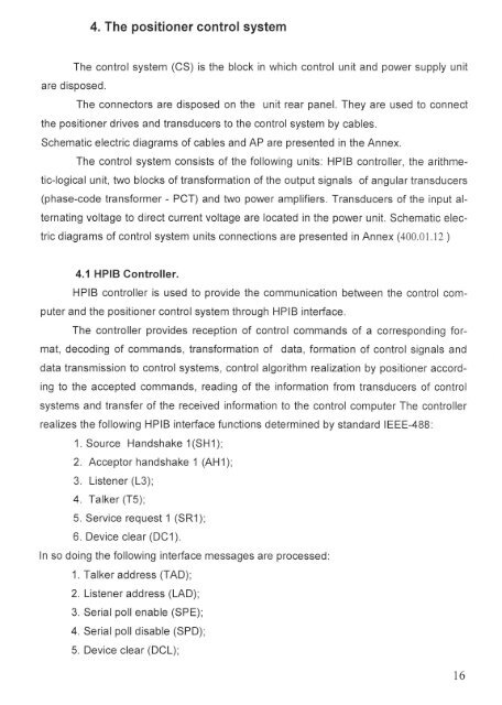
4. The positioner control system<br />
The control system (CS) is the block in which control unit and power supply unit<br />
are disposed.<br />
The connectors are disposed on the unit rear panel. They are used to connect<br />
the positioner drives and transducers to the control system by cables.<br />
Schematic electric diagrams of cables and AP are presented in the Annex.<br />
The control system consists of the following units: HPIB controller, the arithme-<br />
tic-logical unit, two blocks of transformation of the output signals of angular transducers<br />
(phase-code transformer - PCT) and two power amplifiers. Transducers of the input al-<br />
ternating voltage to direct current voltage are located in the power unit. Schematic elec-<br />
tric diagrams of control system units connections are presented in Annex (400.01.12 )<br />
4.1 HPIB Controller.<br />
HPIB controller is used to provide the communication between the control com-<br />
puter and the positioner control system through HPIB interface.<br />
The controller provides reception of control commands of a corresponding for-<br />
mat, decoding of commands, transformation of data, formation of control signals and<br />
data transmission to control systems, control algorithm realization by positioner accord-<br />
ing to the accepted commands, reading of the information from transducers of control<br />
systems and transfer of the received information to the control computer The controller<br />
realizes the following HPIB interface functions determined by standard IEEE-488:<br />
1. Source Handshake 1(SHl);<br />
2. Acceptor handshake 1 (AH1);<br />
3. Listener (13);<br />
4. Talker (T5);<br />
5. Service request 1 (SR1);<br />
6. Device clear (DC1).<br />
In so doing the following interface messages are processed:<br />
1. Talker address (TAD);<br />
2. Listener address (LAD);<br />
3. Serial poll enable (SPE);<br />
4. Serial poll disable (SPD);<br />
5. Device clear (DCL);<br />
16