Design of a Small Size Dielectric Loaded Helical Antenna for ...
Design of a Small Size Dielectric Loaded Helical Antenna for ...
Design of a Small Size Dielectric Loaded Helical Antenna for ...

Create successful ePaper yourself
Turn your PDF publications into a flip-book with our unique Google optimized e-Paper software.
<strong>Design</strong> <strong>of</strong> a <strong>Small</strong> <strong>Size</strong> <strong>Dielectric</strong> <strong>Loaded</strong> <strong>Helical</strong> <strong>Antenna</strong><br />
<strong>for</strong> Satellite Communications<br />
C. H. Niow, K. Mouthaan, J. C. Coetzee * , H. T. Hui<br />
Department <strong>of</strong> Electrical and Computer Engineering, National University <strong>of</strong> Singapore<br />
Block E4, Level 5, Room 45, 4 Engineering Drive 3, Singapore 117576<br />
g0800569@nus.edu.sg<br />
* School <strong>of</strong> Engineering Systems, Queensland University <strong>of</strong> Technology<br />
2 George Street, Brisbane, Queensland, Australia 4000<br />
Abstract — The trade-<strong>of</strong>fs in terms <strong>of</strong> per<strong>for</strong>mance and size <strong>of</strong><br />
an axial-mode helical antenna <strong>for</strong> satellite communications are<br />
investigated. The antenna size is reduced by using a backfire<br />
bifilar helical antenna (BBHA) combined with a dielectric core.<br />
The antenna is designed using Ans<strong>of</strong>t’s HFSS and the results are<br />
verified experimentally. A size reduction <strong>of</strong> 70% is achieved.<br />
The gain at 2.4 GHz is 2.6 dBic with an axial ratio bandwidth <strong>of</strong><br />
400 MHz. The half power bandwidth is 80 degrees and the<br />
antenna return loss is below -10 dB between 2.2 GHz to 2.6 GHz.<br />
A two-element dielectric-loaded BBHA array is simulated using<br />
HFSS and results are compared with a single dielectric-loaded<br />
BBHA.<br />
Index Terms – helical antennas, dielectric loaded antennas,<br />
satellite communication.<br />
T<br />
I. INTRODUCTION<br />
he helical antenna invented by Kraus, can operate in two<br />
different modes: the normal mode and the axial mode [1].<br />
The axial mode is the most practical, as it can be applied in<br />
many applications where high directivity and circular<br />
polarization are required [2]. In order to achieve a good<br />
circular polarization <strong>for</strong> the axial mode, the ratio <strong>of</strong> the<br />
circumference C and the wavelength � must be in the range <strong>of</strong><br />
3/4 < C/� < 4/3 and the spacing between each turn must be<br />
approximately �/4. The circular polarization is optimum when<br />
C/� = 1. The pitch angle should ideally be between 12° and<br />
14° [2]. Due to the large dimensions required to achieve<br />
circular polarization, the helical antenna is usually restricted<br />
to higher frequency applications. Various methods have been<br />
proposed to reduce the antenna size, such as modifying the<br />
helical structure [3]-[5] or introducing dielectric loading [6].<br />
However, antenna size reduction is achieved at the expense <strong>of</strong><br />
a narrower bandwidth.<br />
In this paper, we propose a suitable combination <strong>of</strong> a<br />
modified helical antenna structure and dielectric loading to<br />
reduce the size <strong>of</strong> the helical antenna while maintaining<br />
reasonable antenna per<strong>for</strong>mance with good return loss. The<br />
per<strong>for</strong>mance <strong>of</strong> a closely spaced two-element dielectric<br />
loaded helical antenna array is also investigated using<br />
numerical simulations.<br />
The Backfire Bifilar <strong>Helical</strong> <strong>Antenna</strong> (BBHA) is chosen <strong>for</strong><br />
the modified helical antenna structure, because it does not<br />
require a ground plane unlike conventional helical antennas<br />
[5]. However, the helical structure is still relatively large.<br />
Hence, there is a need to introduce a dielectric rod to reduce<br />
the size further [6]. The introduction <strong>of</strong> the dielectric rod<br />
affects the gain and bandwidth <strong>of</strong> the antenna. There<strong>for</strong>e,<br />
trade-<strong>of</strong>fs have to be made to reduce the antenna size while<br />
achieving reasonable antenna per<strong>for</strong>mance with good return<br />
978-1-4244-2802-1/09/$25.00 ©2009 IEEE<br />
48<br />
loss. This paper presents empirical results to identify the most<br />
suitable design parameters.<br />
II. DESIGN OF REDUCED SIZE HELICAL ANTENNAS<br />
To design the BBHA, various antennas are designed using<br />
both Macor and Teflon <strong>for</strong> the dielectric core. The antennas<br />
are analysed using Ans<strong>of</strong>t HFSS version 11 and validated<br />
through measurements.<br />
A. <strong>Design</strong> <strong>of</strong> a 3-turn BBHA<br />
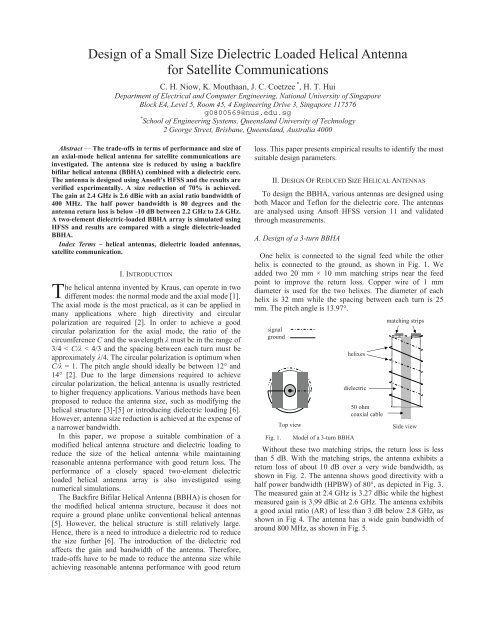
One helix is connected to the signal feed while the other<br />
helix is connected to the ground, as shown in Fig. 1. We<br />
added two 20 mm × 10 mm matching strips near the feed<br />
point to improve the return loss. Copper wire <strong>of</strong> 1 mm<br />
diameter is used <strong>for</strong> the two helixes. The diameter <strong>of</strong> each<br />
helix is 32 mm while the spacing between each turn is 25<br />
mm. The pitch angle is 13.97°.<br />
signal<br />
ground<br />
Top view<br />
helixes<br />
dielectric<br />
50 ohm<br />
coaxial cable<br />
matching strips<br />
Side view<br />
Fig. 1. Model <strong>of</strong> a 3-turn BBHA<br />
Without these two matching strips, the return loss is less<br />
than 5 dB. With the matching strips, the antenna exhibits a<br />
return loss <strong>of</strong> about 10 dB over a very wide bandwidth, as<br />
shown in Fig. 2. The antenna shows good directivity with a<br />
half power bandwidth (HPBW) <strong>of</strong> 80°, as depicted in Fig. 3.<br />
The measured gain at 2.4 GHz is 3.27 dBic while the highest<br />
measured gain is 3.99 dBic at 2.6 GHz. The antenna exhibits<br />
a good axial ratio (AR) <strong>of</strong> less than 3 dB below 2.8 GHz, as<br />
shown in Fig 4. The antenna has a wide gain bandwidth <strong>of</strong><br />
around 800 MHz, as shown in Fig. 5.<br />
Authorized licensed use limited to: National University <strong>of</strong> Singapore. Downloaded on May 03,2010 at 14:47:24 UTC from IEEE Xplore. Restrictions apply.
Fig. 2. Computed and measured return loss <strong>for</strong> 3-turn BBHA<br />
Fig. 3. Computed and measured normalized radiation pattern <strong>for</strong><br />
3-turn BBHA at 2.4 GHz<br />
Fig. 4. Computed and measured AR <strong>for</strong> 3-turn BBHA<br />
Fig. 5. Computed and measured normalized gain <strong>for</strong> 3-turn<br />
BBHA<br />
B. 3-turn BBHA loaded with Teflon<br />
A Teflon rod (�r = 2.1) is introduced inside the helix, which<br />
reduces the antenna size by 50% in volume. The size <strong>of</strong> the<br />
copper strips is optimized using HFSS to 20 mm × 10 mm.<br />
The diameter <strong>of</strong> the antenna is reduced to 26 mm while the<br />
spacing between each turn reduces to 20 mm. The pitch angle<br />
is 13.76°. Fig. 6 shows that the antenna still exhibits a return<br />
loss <strong>of</strong> at least 10 dB from 2.2 GHz onwards. It exhibits good<br />
directivity with an HPBW <strong>of</strong> 70° and a wide gain bandwidth<br />
<strong>of</strong> about 800 MHz, as shown in Figs. 7 and 8 respectively.<br />
49<br />
The gain at 2.4 GHz is 3.27 dBic. The highest gain is 3.98<br />
dBic at 2.6 GHz. The computed gain bandwidth <strong>of</strong> an<br />
unloaded antenna <strong>of</strong> the same size shifts to the higher<br />
frequencies as compared to the antenna loaded with the<br />
dielectric. The AR bandwidth is about 400 MHz, as shown in<br />
Fig. 9. The computed AR bandwidth <strong>of</strong> an unloaded antenna<br />
<strong>of</strong> the same size shifts to higher frequencies.<br />
Fig. 6. Computed and measured return loss <strong>for</strong> 3-turn BBHA<br />
loaded with Teflon<br />
Fig. 7. Computed and measured normalized radiation pattern <strong>for</strong><br />
3-Turn BBHA loaded with Teflon at 2.4 GHz<br />
Fig. 8. Computed and measured normalized gain <strong>for</strong> 3-turn<br />
BBHA loaded with Teflon<br />
Fig. 9. Computed and measured AR <strong>for</strong> 3-turn BBHA loaded with<br />
Teflon<br />
Authorized licensed use limited to: National University <strong>of</strong> Singapore. Downloaded on May 03,2010 at 14:47:24 UTC from IEEE Xplore. Restrictions apply.
C. 3-turn BBHA loaded with Macor<br />
The dielectric Macor has a permittivity <strong>of</strong> 5.8 at 2.4 GHz.<br />
With its introduction, the dimensions <strong>of</strong> the antenna change<br />
to a diameter <strong>of</strong> 20 mm and a spacing between each turn <strong>of</strong><br />
20 mm. The size <strong>of</strong> the copper strips is optimized to 20 mm ×<br />
5 mm. The pitch angle is 17.7°. The antenna volume is only<br />
30 % <strong>of</strong> the original antenna.<br />
The antenna has a return loss <strong>of</strong> at least 10 dB from 2.2<br />
GHz onwards, as shown in Fig. 10. While the antenna retains<br />
its directivity, the back lobe has increased substantially. The<br />
HPBW <strong>of</strong> the antenna is 80° (as shown in Fig. 11) which is<br />
10° wider than the antenna loaded with Teflon. The gain<br />
bandwidth is reduced with the introduction <strong>of</strong> the higher<br />
permittivity dielectric load. The measured gain at 2.4 GHz is<br />
2.6 dBic. The highest gain is 3.7 dBic at 2.6 GHz. This gain<br />
is lower than the gain <strong>of</strong> the antenna loaded with Teflon, as<br />
shown in Fig 12. The gain bandwidth shifts to higher<br />
frequencies <strong>for</strong> the antenna <strong>of</strong> the same size without the<br />
dielectric. The AR bandwidth is about 400 MHz and it shifts<br />
to higher frequencies when the antenna is not loaded with the<br />
dielectric, as shown in Fig. 13.<br />
Fig. 10. Computed and measured return loss <strong>for</strong> 3-turn BBHA<br />
loaded with Macor<br />
Fig. 11. Computed and measured normalized radiation pattern<br />
<strong>for</strong> 3-turn BBHA loaded with Macor at 2.4 GHz<br />
Fig. 12. Computed and measured normalized gain <strong>for</strong> 3-turn<br />
BBHA loaded with Macor<br />
50<br />
Fig. 13. Computed and measured AR <strong>for</strong> 3-turn BBHA loaded with<br />
Macor<br />
D. Per<strong>for</strong>mance Comparison<br />
The dimensions and per<strong>for</strong>mance <strong>of</strong> the three antennas are<br />
compared in Table I, Figs. 14 and 15. It is found that there is<br />
no change in the gain bandwidth when the antenna size is<br />
reduced and loaded with Teflon. However, the gain<br />
bandwidth becomes narrower when the antenna is loaded<br />
with Macor, while the antenna size is reduced further. The<br />
AR bandwidth becomes smaller as the permittivity increases<br />
while the antenna size reduces. The gain at 2.4 GHz reduces<br />
when the permittivity increases.<br />
TABLE I<br />
DIMENSIONS OF EACHBBHA LOADED WITH DIFFERENT<br />
DIELECTRIC<br />
<strong>Dielectric</strong> �r<br />
Diameter<br />
Spacing<br />
between<br />
each<br />
turn<br />
<strong>Size</strong><br />
compared<br />
to<br />
unloaded<br />
BBHA<br />
Air 1 32 mm 25 mm 100 %<br />
Teflon 2.1 26 mm 20 mm 50 %<br />
Macor<br />
5.67 –<br />
6.03<br />
20 mm 20 mm 30 %<br />
Fig. 14. Measured AR <strong>for</strong> 3-turn BBHA loaded with dielectric <strong>of</strong><br />
different permittivity<br />
Fig. 15. Measured gain <strong>for</strong> 3-turn BBHA loaded with dielectric <strong>of</strong><br />
different permittivity<br />
Authorized licensed use limited to: National University <strong>of</strong> Singapore. Downloaded on May 03,2010 at 14:47:24 UTC from IEEE Xplore. Restrictions apply.
III. A REDUCED SIZED TWO-ELEMENT BBHA ARRAY<br />
For satellite communications, usually high-gain antennas<br />
are required. To this end, we have designed a two-element<br />
array using the Macor-loaded BBHA, which is different from<br />
the conventional dielectric loaded helical antenna array [7].<br />
This is because the inter element spacing between the<br />
BBHAs <strong>of</strong> 0.2� at the operating frequency <strong>of</strong> 2.4 GHz is<br />
much smaller and there is no need <strong>for</strong> a ground plane. Hence,<br />
the overall size <strong>of</strong> the Macor-loaded BBHA array is smaller<br />
compared to the conventional dielectric loaded helical<br />
antenna array. Fig. 16 shows the coordinate system employed<br />
here <strong>for</strong> the two element BBHA.<br />
�<br />
y�<br />
2�<br />
1�<br />
Fig. 16. Coordinate system <strong>of</strong> a two element BBHA.<br />
The computed normalized radiation pattern <strong>of</strong> this array is<br />
shown in Figs. 17 and 18 in different � planes. It is found<br />
that when the two elements are placed very close together<br />
with port excitations 180º out-<strong>of</strong>-phase with each other, the<br />
gain increases significantly.<br />
Fig. 17. Computed normalized radiation patterns <strong>for</strong> 1-element<br />
BBHA and 2-element BBHA at � = 0º.<br />
Fig. 18. Computed normalized radiation patterns <strong>for</strong> 1-element<br />
BBHA and 2-element BBHA at � = 90º.<br />
��<br />
x<br />
51<br />
IV. CONCLUSION<br />
This paper considers methods <strong>for</strong> the size reduction <strong>of</strong> the<br />
helical antenna. There is little freedom to vary the pitch angle<br />
and diameter <strong>of</strong> a helical antenna to reduce the size without<br />
affecting the antenna per<strong>for</strong>mance. In addition, the ground<br />
plane <strong>of</strong> a conventional helical antenna needs to be large<br />
enough <strong>for</strong> good antenna per<strong>for</strong>mance.<br />
The bifilar helical antenna (BBHA) is a suitable candidate<br />
<strong>for</strong> size reduction, since it does not require a ground plane.<br />
Introducing a suitable dielectric rod can further reduce the<br />
size. It is found that the antenna size can be reduced by a<br />
dielectric rod with higher permittivity, but at the expense <strong>of</strong><br />
the gain and the bandwidth.<br />
In this paper size reductions in volume are achieved <strong>of</strong> a<br />
BBHA with a Teflon dielectric and a Macor dielectric <strong>of</strong> 50%<br />
and 70% respectively.<br />
ACKNOWLEDGEMENT<br />
This work was partly supported by the departmental vote <strong>of</strong><br />
the Department <strong>of</strong> Electrical and Computer Engineering,<br />
National University <strong>of</strong> Singapore.<br />
REFERENCES<br />
[1] John D. Kraus, “The <strong>Helical</strong> <strong>Antenna</strong>”, Proceedings <strong>of</strong> the IRE,<br />
Volume 37, Issue 3, March 1949 Page(s):263 - 272W.<br />
[2] Constantine A. Balanis, “<strong>Antenna</strong> Theory: Analysis and<br />
<strong>Design</strong>”, Second Edition, Page(s): 505-512.<br />
[3] R.M. Barts, W.L. Stutzman, “A Reduced <strong>Size</strong> <strong>Helical</strong><br />
<strong>Antenna</strong>”, <strong>Antenna</strong>s and Propagation Society International<br />
Symposium, 1997. IEEE., 1997 Digest, Volume 3, 13-18 July<br />
1997 Page(s):1588 - 1591 vol.3.<br />
[4] S.H. Zainud-Deen, N.F.M. Soliman, K.F.A. Hussein, A.A.M.<br />
Shaalan, “Electromagnetic Characteristics <strong>of</strong> Spiro-<strong>Helical</strong><br />
<strong>Antenna</strong>”, Radio Science Conference, 2004. NRSC 2004.<br />
Proceedings <strong>of</strong> the Twenty-First National, Volume, Issue, 16-<br />
18 March 2004 Page(s):B9 - 1-10.<br />
[5] W.T. Patton, “The Backfire Bifilar <strong>Helical</strong> <strong>Antenna</strong>”, Univ.<br />
Illinois <strong>Antenna</strong> Lab Tech. Rept. 61, Sept. 1962.<br />
[6] H. T. Hui, Edward K. N. Yung, and K. W. Leung, "Numerical<br />
and experimental studies <strong>of</strong> a helical antenna loaded by a<br />
dielectric resonator," Radio Sci., vol. 32, no. 2, pp. 295-304,<br />
1997.<br />
[7] Y.A. Ho, H.T. Hui, E.K.N. Yung, “A 1×2 dielectric-loaded<br />
helical antenna array”, <strong>Antenna</strong>s and Propagation Society<br />
International Symposium, 1996.AP-S.Digest Volume 3, Issue ,<br />
21-26 Jul 1996 Page(s):1962 - 1965 vol.3.<br />
Authorized licensed use limited to: National University <strong>of</strong> Singapore. Downloaded on May 03,2010 at 14:47:24 UTC from IEEE Xplore. Restrictions apply.