Aux Positioner Lecture Notes
Aux Positioner Lecture Notes
Aux Positioner Lecture Notes

Create successful ePaper yourself
Turn your PDF publications into a flip-book with our unique Google optimized e-Paper software.
-frequency, Hz. .. 5011<br />
-voltage, V.............. .....220t10%<br />
8) Power consumption, W. ... . no more than 300 ,.,r<br />
9) Carrying capacity, k9... .......S0..<br />
2.1.3. Structure of the article.<br />
The auxiliary positioner consists of the mechanical part and control system. The<br />
control system is a rack connected with the manual control unit by cables. The me-<br />
chanical part is connected with the control system rack by cabres.<br />
1.2 Block diagram of the positioner control system.<br />
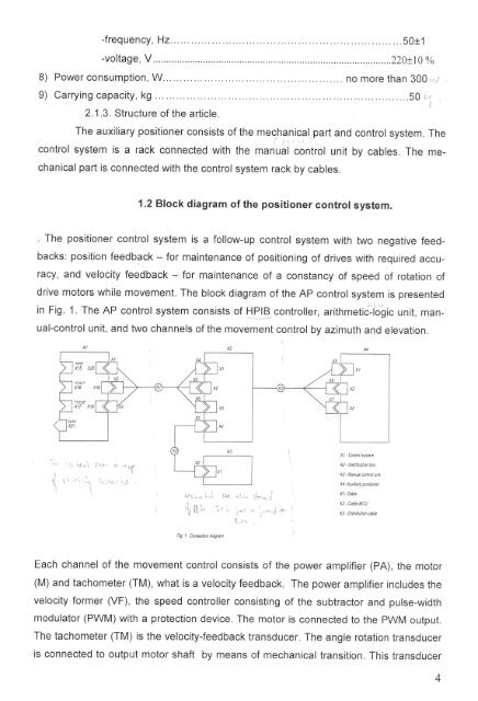
. The positioner control system is a follow-up control system with two negative feed-<br />
backs: position feedback - for maintenance of positioning of drives with required accu-<br />
racy, and velocity feedback - for maintenance of a constancy of speed of rotation of<br />
drive motors while movement. The block diagram of the AP control system is presented<br />
in Fig. 1. The AP control system consists of Hlg controller, arithmetic-logic unit, man-<br />
ual-control unit, and two channels of the movement control by azimuth and elevation.<br />
x16 X16<br />
,{l<br />
Fig I Coneecwn d'ag,an<br />
AI - Conlrol syslen<br />
A2 - Distributtion ba\<br />
A3 - Manual @nlrcl unil<br />
A4 -<strong>Aux</strong>iliaty posiliml<br />
K|- Cable<br />
K2 - Cable MCU<br />
K3 - Dislibution able<br />
Each channel of the movement control consists of the power amplifier (PA), the motor<br />
(M) and tachometer (TM), what is a velocity feedback. The power amplifier includes the<br />
velocity former (VF), the speed controller consisting of the subtractor and pulse-width<br />
modulator (PWM) with a protection device. The motor is connected to the PWM output.<br />
The tachometer (TM) is the velocity-feedback transducer. The angle rotation transducer<br />
is connected to output motor shaft by means of mechanical transition. This transducer