Annex 1: Amendments to the technical specification ... - ERA - Europa
Annex 1: Amendments to the technical specification ... - ERA - Europa
Annex 1: Amendments to the technical specification ... - ERA - Europa

Create successful ePaper yourself
Turn your PDF publications into a flip-book with our unique Google optimized e-Paper software.
Page 1 of 8<br />
Executive Direc<strong>to</strong>r<br />
<strong>Annex</strong> 1: <strong>Amendments</strong> <strong>to</strong> <strong>the</strong> <strong>technical</strong> <strong>specification</strong> for interoperability relating <strong>to</strong> <strong>the</strong> subsystem<br />
‘rolling s<strong>to</strong>ck — freight wagons’ adopted <strong>the</strong> 13 th March 2013.<br />
(1) The article 8, clause 4, of enacting part of Commission Regulation concerning <strong>the</strong> <strong>technical</strong><br />
<strong>specification</strong> for interoperability relating <strong>to</strong> <strong>the</strong> subsystem ‘rolling s<strong>to</strong>ck — freight wagons’ of<br />
<strong>the</strong> rail system in <strong>the</strong> European Union adopted <strong>the</strong> 13 th March 2013, is replaced as following:<br />
“After a transition period of one year after <strong>the</strong> entry in<strong>to</strong> force of this Regulation, newly produced<br />
interoperability constituents “rear-end signal”, shall be covered by <strong>the</strong> required EC declaration of<br />
conformity.”<br />
(2) In clause 1.2 “Geographical scope” <strong>the</strong> text is replaced as following:<br />
“The geographical scope of this TSI is <strong>the</strong> network of <strong>the</strong> whole rail system, composed of:<br />
The trans-European conventional rail system network (TEN) as described in <strong>Annex</strong> I section 1.1<br />
“Network” of Directive 2008/57/EC<br />
The trans-European high-speed rail system network (TEN) as described in <strong>Annex</strong> I section 2.1<br />
“Network” of Directive 2008/57/EC<br />
O<strong>the</strong>r parts of <strong>the</strong> network of <strong>the</strong> whole rail system, following <strong>the</strong> extension of scope as<br />
described in <strong>Annex</strong> I section 4 of Directive 2008/57/EC, and excludes <strong>the</strong> cases referred <strong>to</strong> in<br />
Article 1(3) of Directive 2008/57/EC”.<br />
(3) In clause 4.2.3.5.2 “Running dynamic behaviour” <strong>the</strong> text of <strong>the</strong> fourth paragraph is replaced as<br />
following:<br />
“Running dynamic behavior is permitted <strong>to</strong> be assessed at interoperability constituent level in<br />
accordance with point 6.1.2.1. In this case a specific test or simulation at subsystem level is not required.<br />
(4) In clause 4.2.3.6.1 “Structural design of bogie frame” <strong>the</strong> text of <strong>the</strong> second paragraph is<br />
replaced as following:<br />
“The integrity of <strong>the</strong> structure of a bogie frame is permitted <strong>to</strong> be assessed at interoperability<br />
constituent level in accordance with point 6.1.2.1. In this case a specific test or simulation at subsystem<br />
level is not required.”<br />
(5) In clause 4.2.4.3.2.1 “Service brake” <strong>the</strong> text of <strong>the</strong> second paragraph, second bullet point is<br />
replaced as following:<br />
“ - UIC leaflet 544-1:2013”.<br />
(6) In clause 4.2.4.3.2.2 “Parking brake” <strong>the</strong> text of <strong>the</strong> second paragraph, third bullet point, is<br />
replaced as following:<br />
“ - <strong>the</strong> minimum parking brake performance, considering no wind, shall be determined by calculations<br />
as defined in clause 6 of EN 14531-6:2009.”<br />
(7) In clause 4.2.4.3.3 “Thermal capacity” <strong>the</strong> text of <strong>the</strong> second paragraph is replaced as following:<br />
“The <strong>the</strong>rmal load, <strong>the</strong> unit is capable <strong>to</strong> withstand without any adverse loss of brake performance due<br />
<strong>to</strong> <strong>the</strong>rmal or mechanical effects, shall be defined and expressed in terms of speed, axle load, gradient<br />
and brake distance.”
Page 2 of 8<br />
Executive Direc<strong>to</strong>r<br />
(8) In clause 4.2.4.3.4 “Wheel slide protection (WSP)” <strong>the</strong> text of <strong>the</strong> fourth paragraph is replaced as<br />
following:<br />
“The following types of units shall be fitted with WSP:<br />
Equipped with all types of brake blocks except composite brake blocks, for which <strong>the</strong> maximum<br />
mean utilisation of adhesion is greater than 0,12.<br />
Equipped with disc brakes only and/or with composite brake blocks, for which <strong>the</strong> maximum<br />
mean utilisation of adhesion is greater than 0,11.”<br />
(9) In clause 4.2.6.3. “Attachment devices for rear-end signal” <strong>the</strong> text of <strong>the</strong> clause is replaced as<br />
following:<br />
“On all units designed <strong>to</strong> receive a rear-end signal, two devices at <strong>the</strong> end of <strong>the</strong> unit shall provide for<br />
<strong>the</strong> installation of two lamps or two reflective plates as set out in Appendix E on <strong>the</strong> same height above<br />
rail not higher than 2000 mm. The dimensions and clearance of <strong>the</strong>se attachment devices shall be as<br />
described in chapter 1 of <strong>ERA</strong> <strong>technical</strong> document <strong>ERA</strong>/TD/2012-04/INT version 1.2 of 18.01.2013<br />
published on <strong>the</strong> <strong>ERA</strong> website (http://www.era.europa.eu).”<br />
(10) In clause 4.3.3 “Interface with <strong>the</strong> subsystem “control, command and signalling” <strong>the</strong> table 7<br />
“Interface with control, command and signalling subsystem” is replace by <strong>the</strong> following table:<br />
Reference<br />
Reference in this TSI<br />
4.2.3.3 a) Rolling s<strong>to</strong>ck characteristics<br />
compatible with train detection<br />
system based on track circuits<br />
4.2.3.3 b) Rolling s<strong>to</strong>ck characteristics<br />
compatible with train detection<br />
system based on axle counters<br />
4.2.3.3 c) Rolling s<strong>to</strong>ck characteristics<br />
compatible with train detection<br />
system based on loop equipment<br />
Commission Decision 2012/88/EU<br />
<strong>Annex</strong> A, table A2, index 77<br />
– axle distances (3.1.2.1, 3.1.2.4, 3.1.2.5 and<br />
3.1.2.6),<br />
– vehicle axle load (3.1.7.1),<br />
– impedance between wheels (3.1.9),<br />
– use of composite brake blocks (3.1.6).<br />
– axle distances (3.1.2.1, 3.1.2.2, 3.1.2.5 and<br />
3.1.2.6),<br />
– wheel geometry (3.1.3.1 - 3.1.3.4),<br />
– metal / inductive components-free space<br />
between wheels (3.1.3.5)<br />
– wheel material (3.1.3.6).<br />
– vehicle metal construction ( 3.1.7.2).<br />
(11) In clause 4.4 “Operating rules” <strong>the</strong> text of <strong>the</strong> third paragraph, first bullet point, is replaced as<br />
following:<br />
“- a description of operation in normal mode, including <strong>the</strong> operational characteristics and limitations of<br />
<strong>the</strong> unit (e.g. vehicle gauge, maximum design speed, axle loads, brake performance, compatibility with<br />
train detection systems, permitted environmental conditions).”<br />
(12) In clause 4.7 “Health and safety conditions” <strong>the</strong> text of <strong>the</strong> first paragraph is replaced as<br />
following:
Page 3 of 8<br />
Executive Direc<strong>to</strong>r<br />
“The provisions for health and safety of staff required for <strong>the</strong> operation and maintenance of units are<br />
covered by <strong>the</strong> essential requirements 1.1.5, 1.3.1, 1.3.2, 2.5.1, 2.6.1 set out in <strong>Annex</strong> III <strong>to</strong> Directive<br />
2008/57/EC.”<br />
(13) Section 4.8 “Parameters <strong>to</strong> be recorded in <strong>the</strong> <strong>technical</strong> file”.<br />
a) The title of <strong>the</strong> section in <strong>the</strong> table of contents and in <strong>the</strong> section itself is replaced as following.<br />
“4.8 Parameters <strong>to</strong> be recorded in <strong>the</strong> <strong>technical</strong> file and European register of authorised types of<br />
vehicles”.<br />
b) The following text is added at <strong>the</strong> end of <strong>the</strong> section.<br />
“The data of <strong>the</strong> rolling s<strong>to</strong>ck that must be recorded in <strong>the</strong> “European register of authorised<br />
types of vehicles (<strong>ERA</strong>TV)” are set out in <strong>the</strong> Commission Decision on <strong>the</strong> European register of<br />
authorised types of vehicles (2011/665/EU).”<br />
(14) In clause 6.1.2.1 “Running gear” <strong>the</strong> first sentence is replaced as following:<br />
“The demonstration of conformity for <strong>the</strong> running gear is set out in chapter 2 of <strong>ERA</strong> <strong>technical</strong> document<br />
<strong>ERA</strong>/TD/2013/01/INT version 1.0 of 11.02.2013 published on <strong>the</strong> <strong>ERA</strong> website<br />
(http://www.era.europa.eu)”.\<br />
(15) In clause 6.1.2.3 “Wheel” <strong>the</strong> text in indent (b), second paragraph is replaced as following:<br />
“A verification procedure shall exist <strong>to</strong> ensure at <strong>the</strong> production phase that no defects may<br />
detrimentally affect safety due <strong>to</strong> any change in <strong>the</strong> mechanical characteristics of <strong>the</strong> wheels. The<br />
tensile strength of <strong>the</strong> material in <strong>the</strong> wheel, <strong>the</strong> hardness in <strong>the</strong> rim, <strong>the</strong> fracture <strong>to</strong>ughness (only for<br />
tread-braked wheels), resistance <strong>to</strong> impact, <strong>the</strong> material characteristics and <strong>the</strong> material cleanliness<br />
shall be verified. The verification procedure shall specify <strong>the</strong> batch sampling used for each characteristic<br />
<strong>to</strong> be verified.”<br />
(16) Clause 6.1.2.4 “Axle”<br />
a) The text of <strong>the</strong> first paragraph is replaced by <strong>the</strong> following:<br />
“In addition <strong>to</strong> <strong>the</strong> requirement on <strong>the</strong> assembly above, <strong>the</strong> demonstration of conformity of<br />
mechanical resistance and fatigue characteristics of <strong>the</strong> axle shall be based on clauses 4, 5 and 6<br />
of EN13103:2009+A2:2012”<br />
b) The text of <strong>the</strong> second paragraph is replaced by <strong>the</strong> following:<br />
“The decision criteria for <strong>the</strong> permissible stress are specified in clause 7 of EN<br />
EN13103:2009+A2:2012. A verification procedure shall exist <strong>to</strong> ensure at <strong>the</strong> production phase<br />
that no defects may detrimentally affect safety due <strong>to</strong> any change in <strong>the</strong> mechanical<br />
characteristics of <strong>the</strong> axles. The tensile strength of <strong>the</strong> material in <strong>the</strong> axle, <strong>the</strong> resistance <strong>to</strong><br />
impact, <strong>the</strong> surface integrity, <strong>the</strong> material characteristics and <strong>the</strong> material cleanliness shall be
Page 4 of 8<br />
Executive Direc<strong>to</strong>r<br />
verified. The verification procedure shall specify <strong>the</strong> batch sampling used for each characteristic<br />
<strong>to</strong> be verified.”<br />
(17) In clause 6.2.2.3 “Running dynamic behavior” <strong>the</strong> text of <strong>the</strong> fourth paragraph is replaced by <strong>the</strong><br />
following:<br />
“When an on-track test with normal measuring method is required <strong>the</strong> unit shall be assessed against <strong>the</strong><br />
limit values set out in sections 1.2 and 1.3 of <strong>ERA</strong>/TD/2013/01/INT version 1.0 of 11.02.2013 published<br />
on <strong>the</strong> <strong>ERA</strong> website (http://www.era.europa.eu)”.<br />
(18) In clause 6.2.2.5” Running gear for manual change of wheelsets” <strong>the</strong> text of <strong>the</strong> paragraph<br />
“Changeover between 1435 mm and 1668 mm track gauges” is replaced as following:<br />
“The <strong>technical</strong> solutions described in <strong>the</strong> following figures of <strong>the</strong> UIC leaflet 430-1:2012 are deemed <strong>to</strong><br />
be compliant with <strong>the</strong> requirements in point 4.2.3.6.7 :<br />
– for axle units: figures 9 and 10 of <strong>Annex</strong> B.4, and figure 18 of <strong>Annex</strong> H of UIC leaflet 430-1:2012,<br />
– for bogie units: figure 18 of <strong>Annex</strong> H of UIC leaflet 430-1:2012. ”<br />
(19) In section 6.3 “Subsystem containing components corresponding <strong>to</strong> an interoperability<br />
constituents not holding an EC declaration” <strong>the</strong> text of <strong>the</strong> first paragraph of <strong>the</strong> section is<br />
replaced by following:<br />
“ A Notified Body is permitted <strong>to</strong> issue an EC certificate of verification of a subsystem, even if one or<br />
more of <strong>the</strong> components corresponding <strong>to</strong> interoperability constituents incorporated within <strong>the</strong><br />
subsystem are not covered by a relevant EC declaration of conformity in accordance with this TSI (noncertified<br />
ICs), if <strong>the</strong> constituent was manufactured before <strong>the</strong> entry in<strong>to</strong> force of this TSI and <strong>the</strong> type of<br />
constituent has been:<br />
– used in a subsystem already approved, and<br />
– put in service in at least one Member State before <strong>the</strong> entry in force of this TSI.”<br />
(20) In section 6.5 “Constituents holding an EC declaration of conformity” <strong>the</strong> text of <strong>the</strong> indent b) is<br />
replaced by <strong>the</strong> following:<br />
“The EC certificates of conformity, EC-type examination certificates and EC-design examination<br />
certificates of <strong>the</strong> following ICs shall remain valid under this TSI until <strong>the</strong>ir expiry:<br />
Wheelset;<br />
Wheel;<br />
Axle.”<br />
(21) Appendix B “Specific procedures for running dynamics”<br />
a) The title is replaced by <strong>the</strong> following:<br />
“Appendix B”.<br />
b) The text is replaced by <strong>the</strong> following:<br />
“Not used.”
Braking mode “P”<br />
Braking mode<br />
Changeover (9)<br />
Command Equipment<br />
(22) Appendix C “Additional optional conditions”<br />
Page 5 of 8<br />
Executive Direc<strong>to</strong>r<br />
a) The text in paragraph “1. Manual coupling system”, fifth bullet point is replaced by <strong>the</strong><br />
following:<br />
“ - The clearance for <strong>the</strong> drow hook shall be in accordance with chapter 2 of <strong>ERA</strong> <strong>technical</strong><br />
document <strong>ERA</strong>/TD/2012-04/INT version 1.2 of 18.01.2013 published on <strong>the</strong> era website<br />
(http://www.era.europa.eu).”<br />
b) The text in paragraph “1. Manual coupling system”, ninth bullet point is replaced by <strong>the</strong><br />
following:<br />
“ - The space for shunting staff operation shall be in accordance with chapter 3 of <strong>ERA</strong> <strong>technical</strong><br />
document <strong>ERA</strong>/TD/2012-04/INT version 1.2 of 18.01.2013 published on <strong>the</strong> era website<br />
(http://www.era.europa.eu).”<br />
c) The text in paragraph “2. UIC footsteps and handrails” is replaced by <strong>the</strong> following:<br />
“The unit shall be equipped with footsteps and handrails in accordance with chapter 4 of <strong>ERA</strong><br />
<strong>technical</strong> document <strong>ERA</strong>/TD/2012-04/INT version 1.2 of 18.01.2013.”<br />
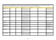
d) Table C.3 “Minimum braking performance for brake modes G and P” is replaced by <strong>the</strong> following<br />
table, including footnotes.<br />
‘’S1’’ (2)<br />
unit type<br />
Empty<br />
Inter-mediate<br />
Loaded<br />
Load status<br />
Requirement for running speed at 100km/h Requirement for running speed at 120km/h<br />
Maximum braking<br />
distance<br />
Smax = 700m<br />
λmin = 65 %<br />
amin = 0,60m/s 2<br />
Smax = 810m<br />
λmin = 55%<br />
amin = 0,51m/s 2<br />
Smax = 700m<br />
λmin = 65 %<br />
amin = 0,60m/s 2<br />
Minimum braking distance<br />
Smin = 390m,<br />
λmax=125%, (130%)*,<br />
amax= 1,15m/s 2<br />
Smin= 390m,<br />
λmax= 125%,<br />
amax =1,15m/s 2<br />
Smin = Max [(S = 480m, λmax=100%,<br />
amax= 0,91m/s 2 ), (S obtained with a<br />
mean retardation force of 16,5 kN<br />
per axle)] (5) .<br />
Maximum braking<br />
distance<br />
Smax = 700m<br />
λmin = 100%<br />
amin = 0,88m/s 2<br />
Minimum braking distance<br />
Smin =580m,<br />
λmax= 125%, (130%)*,<br />
amax=1,08m/s 2
Braking mode “G”<br />
Variable load Relay (10)<br />
“S2” (3)<br />
“SS” (4)<br />
“SS”, “S2”<br />
Empty<br />
Loaded<br />
Loaded<br />
(18t per axle for<br />
brake blocks)<br />
Smax = 480m<br />
λmin = 100% (1)<br />
2 (1)<br />
amin=0,91m/s<br />
Smax = 700m<br />
λmin = 65 %<br />
amin = 0,60m/s 2<br />
Smin = 390m,<br />
λmax=125%, (130%)*,<br />
amax= 1,15m/s 2<br />
Smin = Max [(S = 480m, λmax=100 %,<br />
amax = 0,91m/s 2 ), (S obtained with a<br />
mean retardation force of 16,5 kN<br />
per axle)] (6) .<br />
There shall be no separate<br />
assessment of <strong>the</strong> braking<br />
performance of units in position G.<br />
A unit’s braked weight in position G<br />
is <strong>the</strong> result of <strong>the</strong> braked weight in<br />
position P (see UIC 544-1:2012)<br />
Page 6 of 8<br />
Smax = 700m<br />
λmin = 100%<br />
amin = 0,88m/s 2<br />
Smax (8) = Max [S = 700m, λmax=100%,<br />
Executive Direc<strong>to</strong>r<br />
Smin =580m,<br />
λmax= 125%, (130%)*,<br />
amax=1,08m/s 2<br />
amax = 0,88m/s 2 ), (S obtained with a mean retardation<br />
force of 16kN per axle)] (7) .<br />
*only for two stage load brake (changeover command) and P10 (cast iron blocks with 10 ‰ phosphor)-<br />
or LL-brake blocks<br />
(1) “a” = ((Speed (Km/h))/3,6)^2)/(2x(S-((Te)x(Speed (Km/h)/3,6)))), with Te=2sec. Distance calculation<br />
EN 14531-1:2005 section 5.11<br />
(2) a unit “S1” is a unit with empty/load device. Maximum load per axle is 22,5 t.<br />
(3) a unit “S2” is a unit with a variable load relay. Maximum load per axle is 22,5 t.<br />
(4) a unit “SS” shall be equipped with a variable load relay. Maximum load per axle is 22,5 t.<br />
(5) The maximum mean retardation force admitted (for running speed at 100km/h) is 18x0,91 = 16,5<br />
kN/axle. This value comes from <strong>the</strong> maximum braking energy input permitted on a clasp braked wheel<br />
with a nominal new diameter in <strong>the</strong> range of<br />
[920 mm; 1 000 mm] during braking (<strong>the</strong> brake weight shall be limited <strong>to</strong> 18 <strong>to</strong>nnes/axle).<br />
(6) The maximum mean retardation force admitted (for running speed at 100km/h) is 18x0,91 = 16,5<br />
kN/axle. This value comes from <strong>the</strong> maximum braking energy input permitted on a clasp braked wheel<br />
with a nominal new diameter in <strong>the</strong> range of<br />
[920 mm; 1 000 mm] during braking (<strong>the</strong> brake weight shall be limited <strong>to</strong> 18 <strong>to</strong>nnes/axle). Usually a unit,<br />
with V max = 100 km/h and fitted with a variable relay is designed <strong>to</strong> obtain λ = 100% up <strong>to</strong> 14.5 t/axle.
Page 7 of 8<br />
Executive Direc<strong>to</strong>r<br />
(7) The maximum mean retardation force admitted (for running speed at 120km/h) is 18x0,88 = 16<br />
kN/axle. This value comes from <strong>the</strong> maximum braking energy input permitted on a clasp braked wheel<br />
with a nominal new diameter in <strong>the</strong> range of<br />
[920 mm; 1 000 mm] during braking (<strong>the</strong> brake weight shall be limited <strong>to</strong> 18 <strong>to</strong>nnes). The mass/axle is<br />
limited <strong>to</strong> 20 t/axle and <strong>the</strong> corresponding λ is 90%. If it is required λ > 100% with mass/axle > 18 t <strong>the</strong>n it<br />
is necessary <strong>to</strong> consider ano<strong>the</strong>r kind of brake.<br />
(8) λ must not exceed 125%, considering for brake only on wheels (brake blocks), <strong>the</strong> maximum mean<br />
retardation force admitted of 16 kN/axle (for running speed at 120km/h).<br />
(9) Changeover in accordance with EN 15624:2008+A1:2010.<br />
(10) Variable load relay in accordance with EN 15611:2008+A1:2010 in combination with variable load<br />
sensing device in accordance with EN 15625:2008+A1:2010.<br />
(23) Appendix D “Standards or normative documents referred <strong>to</strong> in this TSI”<br />
a) First table - <strong>the</strong> text “Content of prEN 16235 included in Appendix B of this TSI” of <strong>the</strong> cell under<br />
<strong>the</strong> column “Reference <strong>to</strong> manda<strong>to</strong>ry standards” 17 th row, is replaced by <strong>the</strong> following.<br />
“<strong>ERA</strong>/TD/2013/01/INT version 1.0 of 11.02.2013.”<br />
b) First table - <strong>the</strong> text “Content of prEN 16235 included in Appendix B of this TSI” of <strong>the</strong> cell under<br />
<strong>the</strong> column “Reference <strong>to</strong> manda<strong>to</strong>ry standards” 20 th row, is replaced by <strong>the</strong> following.<br />
“<strong>ERA</strong>/TD/2013/01/INT version 1.0 of 11.02.2013.”<br />
c) First table - <strong>the</strong> text “EN 13103:2009+A1:2010” of <strong>the</strong> cell under <strong>the</strong> column “Reference <strong>to</strong><br />
manda<strong>to</strong>ry standards” 28 th row, is replaced by <strong>the</strong> following.<br />
“EN13103:2009+A2:2012”.<br />
d) First table - <strong>the</strong> text “UIC 430-1:2006” of <strong>the</strong> cell under <strong>the</strong> column “Reference <strong>to</strong> manda<strong>to</strong>ry<br />
standards” 32 nd row, is replaced by <strong>the</strong> following.<br />
“UIC 430-1:2012”.<br />
e) First table – <strong>the</strong> text “UIC 544-1:2012” of <strong>the</strong> cell under <strong>the</strong> column “Reference <strong>to</strong> manda<strong>to</strong>ry<br />
standards” 35 th row, is replaced by <strong>the</strong> following.<br />
“UIC 544-1:2013”.<br />
f) First table - <strong>the</strong> text “<strong>ERA</strong> <strong>technical</strong> document <strong>ERA</strong>/TD/2012-04/INT version 1.0 of 04.06.2012”<br />
of <strong>the</strong> cell under <strong>the</strong> column “Reference <strong>to</strong> manda<strong>to</strong>ry standards” last row, is replaced by <strong>the</strong><br />
following.<br />
“<strong>ERA</strong>/TD/2012-04/INT version 1.2 of 18.01.2013”.<br />
g) Second table - <strong>the</strong> text “<strong>ERA</strong> <strong>technical</strong> document <strong>ERA</strong>/TD/2012-04/INT version 1.0 of<br />
04.06.2012” of <strong>the</strong> cell of <strong>the</strong> column “Standard / UIC leaflet” 4 th row is replaced by <strong>the</strong><br />
following.<br />
“<strong>ERA</strong>/TD/2012-04/INT version 1.2 of 18.01.2013”
Page 8 of 8<br />
Executive Direc<strong>to</strong>r<br />
h) Second table - <strong>the</strong> text “<strong>ERA</strong> <strong>technical</strong> document <strong>ERA</strong>/TD/2012-04/INT version 1.0 of<br />
04.06.2012” of <strong>the</strong> cell of <strong>the</strong> column “Standard / UIC leaflet” 6 th row is replaced by <strong>the</strong><br />
following.<br />
“<strong>ERA</strong>/TD/2012-04/INT version 1.2 of 18.01.2013”