Installation Manual COLOR GPS PLOTTER GP-7000 - Furuno USA
Installation Manual COLOR GPS PLOTTER GP-7000 - Furuno USA
Installation Manual COLOR GPS PLOTTER GP-7000 - Furuno USA

Create successful ePaper yourself
Turn your PDF publications into a flip-book with our unique Google optimized e-Paper software.
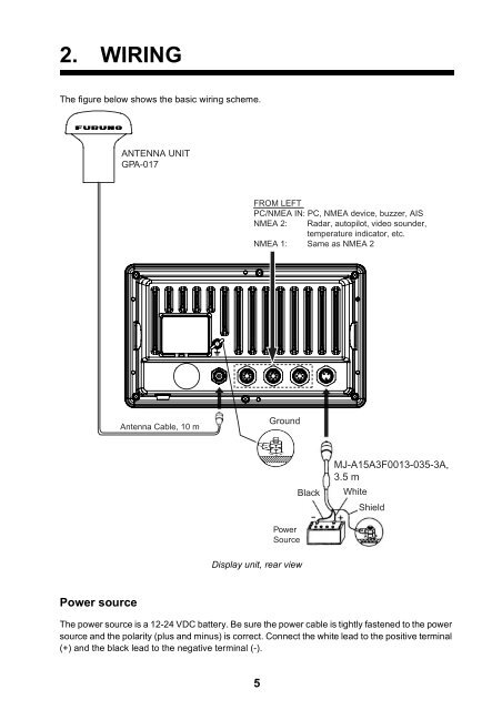
2. WIRING<br />
The figure below shows the basic wiring scheme.<br />
Power source<br />
ANTENNA UNIT<br />
<strong>GP</strong>A-017<br />
Antenna Cable, 10 m<br />
FROM LEFT<br />
PC/NMEA IN: PC, NMEA device, buzzer, AIS<br />
NMEA 2: Radar, autopilot, video sounder,<br />
temperature indicator, etc.<br />
NMEA 1: Same as NMEA 2<br />
Display unit, rear view<br />
The power source is a 12-24 VDC battery. Be sure the power cable is tightly fastened to the power<br />
source and the polarity (plus and minus) is correct. Connect the white lead to the positive terminal<br />
(+) and the black lead to the negative terminal (-).<br />
5<br />
Ground<br />
Power<br />
Source<br />
Black<br />
MJ-A15A3F0013-035-3A,<br />
3.5 m<br />
White<br />
Shield