technical sheet - Tractel
technical sheet - Tractel
technical sheet - Tractel

Create successful ePaper yourself
Turn your PDF publications into a flip-book with our unique Google optimized e-Paper software.
<strong>technical</strong><br />
<strong>sheet</strong><br />
MC1139<br />
F<br />
F<br />
A<br />
F max.<br />
0,25 m<br />
A<br />
max.<br />
1,13 m<br />
A<br />
max.<br />
2,00 m<br />
2,32 - 5,92 m<br />
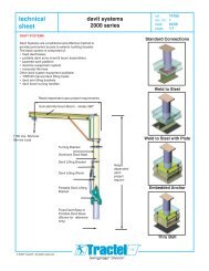
SUSPENSION JIBS<br />
for temporary<br />
suspended platforms<br />
*replaces <strong>sheet</strong>s T-482-12/95 (DELTA) and T-176-10/91 (parapet clamps)<br />
In most applications, it is possible to use a<br />
system of mobile suspension jibs in the roof for<br />
the attachment of temporary suspended<br />
platforms.<br />
We offer the following solutions.<br />
F<br />
A<br />
max.<br />
1,13 m<br />
The equipment conforms to EU<br />
Directives and is manufactured<br />
in accordance with ISO 9002.<br />
DELTA I<br />
2,32 - 5,92 m<br />
DELTA II<br />
2,32 - 5,92 m<br />
DELTA III<br />
2,32 - 5,92 m<br />
DELTA IV<br />
DIN EN ISO 9002<br />
010<br />
005<br />
ref.: T-482*<br />
rev. no.: 3<br />
date: 12/97<br />
page: 1/4<br />
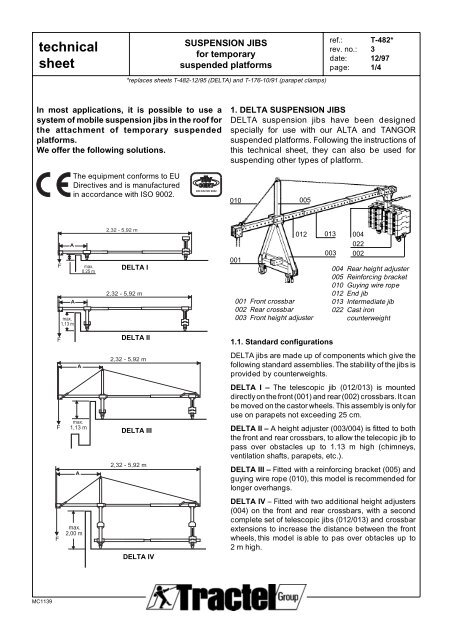
1. DELTA SUSPENSION JIBS<br />
DELTA suspension jibs have been designed<br />
specially for use with our ALTA and TANGOR<br />
suspended platforms. Following the instructions of<br />
this <strong>technical</strong> <strong>sheet</strong>, they can also be used for<br />
suspending other types of platform.<br />
001<br />
012<br />
001 Front crossbar<br />
002 Rear crossbar<br />
003 Front height adjuster<br />
013<br />
003<br />
004<br />
022<br />
002<br />
004 Rear height adjuster<br />
005 Reinforcing bracket<br />
010 Guying wire rope<br />
012 End jib<br />
013 Intermediate jib<br />
022 Cast iron<br />
counterweight<br />
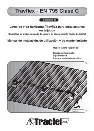
1.1. Standard configurations<br />
DELTA jibs are made up of components which give the<br />
following standard assemblies. The stability of the jibs is<br />
provided by counterweights.<br />
DELTA I – The telescopic jib (012/013) is mounted<br />
directly on the front (001) and rear (002) crossbars. It can<br />
be moved on the castor wheels. This assembly is only for<br />
use on parapets not exceeding 25 cm.<br />
DELTA II – A height adjuster (003/004) is fitted to both<br />
the front and rear crossbars, to allow the telecopic jib to<br />
pass over obstacles up to 1.13 m high (chimneys,<br />
ventilation shafts, parapets, etc.).<br />
DELTA III – Fitted with a reinforcing bracket (005) and<br />
guying wire rope (010), this model is recommended for<br />
longer overhangs.<br />
DELTA IV – Fitted with two additional height adjusters<br />
(004) on the front and rear crossbars, with a second<br />
complete set of telescopic jibs (012/013) and crossbar<br />
extensions to increase the distance between the front<br />
wheels, this model is able to pas over obtacles up to<br />
2 m high.
<strong>technical</strong><br />
<strong>sheet</strong><br />
1.2. Maximum permitted overhang (A)<br />
MC1139<br />
SUSPENSION JIBS<br />
for temporary<br />
suspended platforms<br />
*replaces <strong>sheet</strong>s T-482-12/95 (DELTA) and T-176-10/91 (parapet clamps)<br />
working load limit DELTA DELTA<br />
(WWL)* per jib I + II III + IV<br />
300 kg 1,00 m 2,00 m<br />
500 kg 0,80 m 2,00 m<br />
700 kg - 1,40 m<br />
800 kg - 1,20 m<br />
*"Maximum loading" should be taken to mean the nominal capacity of<br />
the hoist and not the actual suspended load.<br />
The loads indicated above apply to the capacities of our TIRAK hoists<br />
X-300, X-500, X-720 and T-1020.<br />
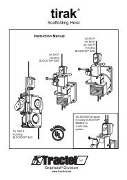
CMU<br />
2x<br />
A B<br />
Ra<br />
1.3. Calculation of the number of counterweights<br />
The tables below (page 3/4) illustrate the number of<br />
counterweigths needed for the different capacities<br />
(WLL) depending on the overhang (A) and the<br />
distance (B) behind the fulcrum.<br />
The tables show that it is always best to have the<br />
maximum distance (B) behind the fulcrum, space<br />
permitting, to reduce the number of counterweights,<br />
making assembly and dismantling much easier.<br />
It should be noted that the total length of the<br />
telescopic jib (A + B) should not excedd 5.60 m.<br />
N<br />
Rb<br />
ref.: T-482*<br />
rev. no.: 3<br />
date: 12/97<br />
page: 2/4<br />
1.4. Installation and operating advice<br />
– Before assembly of the DELTA mobile suspension<br />
jibs, always check to ensure that the roof is<br />
suitable to take the relevant loadings. If necessary<br />
check the loadings with the authorities responsable<br />
for the building.<br />
– Adjust the jib centres to suit the stirrup centres of<br />
the platform used.<br />
– The traversing castors should always stand on<br />
planks to protect the roof covering and the<br />
weatherproofing, as well as to spread the loadings<br />
more evenly, and facilitate moving the jib.<br />
– Never allow the jibs to rest on the parapet.<br />
– When assembly is complete, lock the brake on the<br />
castor wheels.<br />
– The jibs must be completely assembled and fitted<br />
with all the required counterweights before the<br />
platform is attached to the jibs.<br />
– Conversely, the platform shouild be detached<br />
from the jibs before the counterweights are<br />
removed.<br />
– Regularly check the condition of the various<br />
components. Use only original manufacturer's<br />
spare parts and components.<br />
– The suspension jibs should be anchored at the<br />
rear to a fixed point using a sling.
<strong>technical</strong><br />
<strong>sheet</strong><br />
MC1139<br />
SUSPENSION JIBS<br />
for temporary<br />
suspended platforms<br />
*replaces <strong>sheet</strong>s T-482-12/95 (DELTA) and T-176-10/91 (parapet clamps)<br />
Platforms fitted with TIRAK X-300 hoists. Nominal capacity per hoist: F = 300 kg<br />
ref.: T-482*<br />
rev. no.: 3<br />
date: 12/97<br />
page: 3/4<br />
Overhang Distance behind the fulcrum B (m) Ra max* Rb max**<br />
A m 1,4 1,6 1,8 2,0 2,4 2,8 3,2 3,6 4,0 4,4 5,0 5,2 (kg) (kg)<br />
0,4 9 7 6 6 4 4 2 1 1 1 0 0 300 240<br />
without 0,6 14 12 11 9 7 5 4 4 3 2 2 310 290<br />
guy wire 0,8 19 17 15 13 11 8 7 6 5 4 340 340<br />
1,0 24 21 19 17 12 10 9 8 7 6 380 390<br />
1,2 30 26 23 20 16 13 11 10 9 8 420 460<br />
with 1,4 35 30 27 23 19 16 14 12 10 450 510<br />
guy wire 1,6 35 30 27 22 19 16 14 12 470 490<br />
1,8 34 31 25 21 18 16 480 470<br />
2,0 34 28 24 21 18 490 460<br />
N = Number of counterweights per jib<br />
Platforms fitted with TIRAK X-500 hoists. Nominal capacity per hoist: F = 500 kg<br />
Overhang Distance behind the fulcrum B (m) Ra max* Rb max**<br />
A m 1,4 1,6 1,8 2,0 2,4 2,8 3,2 3,6 4,0 4,4 5,0 5,2 (kg) (kg)<br />
without 0,4 16 13 12 10 8 7 5 4 3 3 2 2 430 320<br />
guy wire 0,6 24 21 19 17 13 10 9 8 7 6 5 490 410<br />
0,8 33 29 25 23 19 15 13 11 10 9 540 510<br />
1,0 36 32 29 22 19 16 14 13 11 570 530<br />
1,2 35 28 23 20 18 16 14 590 500<br />
with 1,4 33 28 24 21 19 590 470<br />
guy wire 1,6 32 28 25 22 590 450<br />
1,8 32 28 590 450<br />
2,0 36 31 610 500<br />
N = Number of counterweights per jib<br />
Platforms fitted with TIRAK X-720 hoists. Nominal capacity per hoist: F = 700 kg<br />
Overhang Distance behind the fulcrum B (m) Ra max* Rb max**<br />
A m 1,4 1,6 1,8 2,0 2,4 2,8 3,2 36 4,0 4,4 5,0 5,2 (kg) (kg)<br />
0,4 23 19 17 15 12 10 8 7 6 5 4 4 590 410<br />
0,6 35 30 27 24 19 15 13 12 10 9 8 660 550<br />
with 0,8 36 32 27 21 19 16 14 13 700 540<br />
guy wire 1,0 32 28 24 21 19 17 700 470<br />
1,2 34 29 26 23 21 720 480<br />
1,4 35 31 27 730 490<br />
N = Number of counterweights per jib<br />
Platforms fitted with TIRAK T-1020 hoists. Nominal capacity per hoist: F = 800 kg<br />
Overhang Distance entre appuis B (m) Ra max* Rb max**<br />
A m 1,4 1,6 1,8 2,0 2,4 2,8 3,2 36 4,0 4,4 5,0 5,2 (kg) (kg)<br />
0,4 26 22 20 18 14 12 9 8 7 6 5 5 670 450<br />
with 0,6 35 31 27 22 18 15 14 12 11 9 740 540<br />
guy wire 0,8 31 25 22 19 17 15 750 460<br />
1,0 32 28 24 22 19 770 460<br />
1,2 34 30 27 24 790 480<br />
N = Noumber of counterweights per jib<br />
* Ra max = dynamic response for each front wheel, with the platform suspended (dynamic coefficient = 1,25). For final response for<br />
each front wheel (operating load multiplied by a coefficient of 3): multiply the Ra max. values by approximately 2.2.<br />
** Rb max = maximum response for each rear wheel, with the platform on the ground.