Manual (pdf) - Northern Tool + Equipment
Manual (pdf) - Northern Tool + Equipment
Manual (pdf) - Northern Tool + Equipment

You also want an ePaper? Increase the reach of your titles
YUMPU automatically turns print PDFs into web optimized ePapers that Google loves.
Automotive: Lightbars<br />
ENGINEERING COMPANY INC.<br />
Route 145, Winthrop Road,<br />
Chester, Connecticut 06412<br />
Phone: (860) 526-9504<br />
Fax: (860) 526-4078<br />
Internet: www.whelen.com<br />
Sales e-mail: autosale@whelen.com<br />
Canadian Sales e-mail: autocan@whelen.com<br />
Customer Service e-mail: custserv@whelen.com<br />
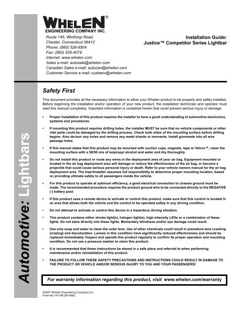
Safety First<br />
©2007 Whelen Engineering Company Inc.<br />
Form No.14114B (041408)<br />
®<br />
Page 1<br />
Installation Guide:<br />
Justice Competitor Series Lightbar<br />
This document provides all the necessary information to allow your Whelen product to be properly and safely installed.<br />
Before beginning the installation and/or operation of your new product, the installation technician and operator must<br />
read this manual completely. Important information is contained herein that could prevent serious injury or damage.<br />
Proper installation of this product requires the installer to have a good understanding of automotive electronics,<br />
systems and procedures.<br />
If mounting this product requires drilling holes, the installer MUST be sure that no vehicle components or other<br />
vital parts could be damaged by the drilling process. Check both sides of the mounting surface before drilling<br />
begins. Also de-burr any holes and remove any metal shards or remnants. Install grommets into all wire<br />
passage holes.<br />
If this manual states that this product may be mounted with suction cups, magnets, tape or Velcro, clean the<br />
mounting surface with a 50/50 mix of isopropyl alcohol and water and dry thoroughly.<br />
Do not install this product or route any wires in the deployment area of your air bag. <strong>Equipment</strong> mounted or<br />
located in the air bag deployment area will damage or reduce the effectiveness of the air bag, or become a<br />
projectile that could cause serious personal injury or death. Refer to your vehicle owners manual for the air bag<br />
deployment area. The User/Installer assumes full responsibility to determine proper mounting location, based<br />
on providing ultimate safety to all passengers inside the vehicle.<br />
For this product to operate at optimum efficiency, a good electrical connection to chassis ground must be<br />
made. The recommended procedure requires the product ground wire to be connected directly to the NEGATIVE<br />
(-) battery post.<br />
If this product uses a remote device to activate or control this product, make sure that this control is located in<br />
an area that allows both the vehicle and the control to be operated safely in any driving condition.<br />
Do not attempt to activate or control this device in a hazardous driving situation.<br />
This product contains either strobe light(s), halogen light(s), high-intensity LEDs or a combination of these<br />
lights. Do not stare directly into these lights. Momentary blindness and/or eye damage could result.<br />
Use only soap and water to clean the outer lens. Use of other chemicals could result in premature lens cracking<br />
(crazing) and discoloration. Lenses in this condition have significantly reduced effectiveness and should be<br />
replaced immediately. Inspect and operate this product regularly to confirm its proper operation and mounting<br />
condition. Do not use a pressure washer to clean this product.<br />
It is recommended that these instructions be stored in a safe place and referred to when performing<br />
maintenance and/or reinstallation of this product.<br />
FAILURE TO FOLLOW THESE SAFETY PRECAUTIONS AND INSTRUCTIONS COULD RESULT IN DAMAGE TO<br />
THE PRODUCT OR VEHICLE AND/OR SERIOUS INJURY TO YOU AND YOUR PASSENGERS!<br />
For warranty information regarding this product, visit www.whelen.com/warranty
Permanent Mounting:<br />
1. Locate the mounting foot and mounting plate included with your lightbar. If not already present, install the<br />
mounting plate onto the mounting foot. When properly positioned, this plate is centered from side to side<br />
on the mounting foot.<br />
2. Flip lightbar upside-down to expose bottom of extrusion and place mounting foot onto<br />
extrusion.<br />
3. Rotate the mounting foot 90° in a counter-clockwise direction. Make sure that the<br />
edges of the mounting foot swing into position under the extrusion mounting lip.<br />
4. Repeat this procedure for the remaining mounting foot and return the lightbar to its right<br />
side-up position.<br />
5. Position the lightbar onto the vehicle roof in the desired mounting location. One often<br />
selected location is directly above the B-pillars. This area is the strongest part of the<br />
roof. Refer to your lightbar manual for your lightbars cable exit location, to be sure that<br />
the lightbar is facing the proper direction.<br />
6. Adjust the two mounting feet outwards so that they are as close to the edge of the roof<br />
as possible. Make sure that both mounting feet are in full contact with the roof (See<br />
below). Be sure that there is no less than 1/2” clearance between the roof and the<br />
lightbar at their closest point. When the mounting feet are in their proper position, lightly<br />
tighten the mounting foot allen head set screws.<br />
7. Turn the lightbar upside down and firmly tighten all of the set screws from step 6 (2 or 4<br />
per side).<br />
8. On the mounting foot, remove either the two outer or inner rubber mounting pads. Carefully<br />
Slide Bolt Mounting:<br />
1. Remove one lightbar endcap.<br />
2.<br />
2. position and secure them with the set screws<br />
3. Position the lightbar onto the vehicle and mark the four bolt hole<br />
3. locations on the mounting surface<br />
Insert slide bolts into base,slide them across to their mounting<br />
Mounting Mounting Mounting<br />
Surface Surface Surface<br />
4. Drill the four holes with an appropriately sized drill bit<br />
5. Replace end cap. Insert bolts into their 4 mounting holes. Secure<br />
5. the lightbar with the supplied hardware<br />
Page 2<br />
Standard<br />
Mounting<br />
Foot<br />
Mounting<br />
Plate<br />
remove the mounting pad’s guide dart so the hole through the center of the pad is exposed then<br />
replace the pad (Standard foot only). On the adjustable foot, use the hole in the pad as a guide to drill<br />
the two holes into the mounting foot.<br />
9. Place the lightbar in its final mounting position on<br />
the vehicle, mark the mounting hole locations off<br />
onto the mounting surface, remove the lightbar and<br />
drill the mounting holes.<br />
10. Place the lightbar back onto the vehicle lined up<br />
with the mounting holes and secure the mounting<br />
feet to the vehicle using the supplied hardware.<br />
Mounting<br />
Pad<br />
Washer<br />
Insert into<br />
the base here.<br />
Tighten both set screws<br />
to secure to base<br />
Mounting<br />
Pad<br />
Nut<br />
Washer<br />
Bolt<br />
Nut<br />
Mounting<br />
Plate<br />
Adjustable<br />
Mounting<br />
Foot<br />
1/2" MIN. CLEARANCE<br />
IMPORTANT: For strap mounting, be sure you have the right sized<br />
lightbar for your vehicle. The bar should be approximately the same<br />
width as the vehicle roof. If too large or small it will not mount properly<br />
and may come loose during driving.<br />
NOTE: Unless otherwise specified, the lightbar mounting feet must be sitting as close to the edge of the roof as possible. They must also be<br />
in full contact with the roof and not be hanging off the edge.<br />
Slide Bolt Mounting (Permanent):<br />
This lightbar mounts with 4 bolts affixed to mounting plates that slide into the track on the bottom of the lighbar base. Figures 1 and 1a show how the slide bolt assembly slides<br />
into your lightbars base and mounts onto the vehicle. Use an appropriately sized drill bit sized for a 1/2 - #13 X 2” bolt, to drill the mounting holes.<br />
Strap Mounting:<br />
Driver-side<br />
cable exit<br />
1. Locate the mounting foot, mounting plate and tinnerman plate included with<br />
your lightbar. If not already present, install the mounting plate onto the<br />
mounting foot. When properly positioned, this plate is centered from side to<br />
side on the mounting foot.<br />
2. Flip the lightbar upside-down to expose the bottom of the extrusion and place<br />
the mounting foot onto the extrusion.<br />
3. Rotate the mounting foot 90° in a counter-clockwise direction. Make sure that<br />
the edges of the mounting foot swing into position under<br />
the extrusion mounting lip. Install a tinnerman plate onto<br />
Cable Access<br />
FRONT<br />
Hole<br />
Passngr.-side<br />
cable exit<br />
Drill the cable access hole in the<br />
appropriate area for your lightbar.<br />
the extrusion in the same manner.<br />
4. Repeat this procedure for the<br />
remaining mounting foot and<br />
tinnerman plate and return the<br />
lightbar to its right side-up position.<br />
5. Position the lightbar onto the vehicle roof in the desired mounting location. One<br />
often selected location is directly above the B-pillars. This area is the strongest<br />
part of the roof. Refer to your lightbar manual for cable exit location, to be sure<br />
that the lightbar is facing the proper direction.<br />
6. Adjust the two mounting feet outwards so that they are as close to the edge of<br />
the roof as possible. Both mounting feet must be in full contact with the roof. Be<br />
sure that there is no less than 1/2” clearance<br />
between the roof and the lightbar at their<br />
closest point. When the mounting feet are in<br />
their proper position, lightly tighten the<br />
mounting foot allen head set screws.<br />
7. Return the lightbar to an upside down<br />
position. Slide each tinnerman plate<br />
outwards until it is fully engaged with its<br />
corresponding mounting foot. With the<br />
mounting feet and tinnerman plates in their<br />
proper positions firmly tighten all of the set<br />
screws (2 or 4 per side). Flip the lightbar<br />
right side-up and return it to its mounting<br />
position.
8. Open both drivers side doors. In the area directly below the mounting foot,<br />
carefully pull the drivers side weather-strip away from the vehicle. Remove<br />
enough so that the area where the mounting strap will be secured to the<br />
vehicle is exposed. Repeat procedure for passenger side.<br />
9. Insert the mounting strap through the mounting foot. Be sure that the strap fits<br />
flush against the area where it will be secured onto the vehicle. Insert the<br />
tension bolt through the mounting strap and into the tinnerman nut on the<br />
tinnerman plate. Tighten slightly with a long shafted, Phillips screwdriver.<br />
Repeat procedure for passenger side.<br />
Standard Mounting Foot / Model MKEZ<br />
Tension<br />
Bolt<br />
Mounting<br />
Pad<br />
5" Mounting Foot<br />
SHEET<br />
METAL<br />
SCREWS<br />
Mounting<br />
Screw<br />
METAL SCREW<br />
Mounting<br />
Foot<br />
BOLT<br />
STRAP<br />
Mounting<br />
Strap<br />
Tinnerman<br />
Plate<br />
Mounting<br />
Plate<br />
MOUNTING FOOT<br />
EXTENSION<br />
NUT<br />
SPLIT LOCK<br />
WASHER<br />
NOTE: The mounting straps are made to fit the contours of individual<br />
NOTE: vehicles. The strap shown here is for example only. The strap<br />
NOTE: for your vehicle may look different.<br />
Installation: If your lightbar has a 5” mounting foot, it will assemble<br />
differently than the standard mounting foot. It also uses an<br />
extension to compensate for the extra height. Follow these<br />
illustrations for assembly. Mounting to the lightbar is the same.<br />
Lightbar Cables:<br />
Tighten screws<br />
with torque wrench<br />
set at 35 to 40 in/lbs<br />
TINNERMAN<br />
NUT<br />
FOOT<br />
ANCHOR<br />
PLATE<br />
VEHICLE ROOF<br />
Standard Lightbar: This lightbar uses a 4 conductor cable for LED’s, a 6 conductor<br />
cable for Halogen and a 3 conductor cable for Options. There is also an option for<br />
Brake-Tail to connect to your brake lights. Extend the 3, 4 and 6 conductor cables<br />
towards your switch panel. The instructions included with your switches will provide<br />
switch wiring information. The optional brake-tail cable connects to the brake lights.<br />
Refer to the next page for wire designations and fusing.<br />
WARNING! All Customer supplied wires that connect to the positive terminal of<br />
the battery must be sized to supply at least 125% of the maximum operating<br />
current and FUSED at the battery to carry that load. DO NOT USE CIRCUIT<br />
BREAKERS WITH THIS PRODUCT!<br />
Halogen Cable:<br />
WHITE: Apply +12 volts to activate the TakeDowns or Worklight<br />
GREEN: Apply +12 volts to activate the Passenger Side Alley lights<br />
RED: Apply +12 volts to activate the Driver Side Alley light.<br />
BLUE: Apply +12 volts to activate the Takedowns in flashing mode.<br />
Page 3<br />
10. If your mounting strap has mounting holes in the end of the strap, use these<br />
holes as a template to drill appropriately sized pilot holes through the strap and<br />
into the vehicle. Repeat for passenger side of the vehicle.<br />
11. Firmly tighten the tension bolts to secure the lightbar to the vehicle.<br />
NOTE: Model MKAJ is an adjustable mounting foot. On this model you may<br />
loosen the screws on the rear of the foot and adjust the angle of the lightbar.<br />
This feature can be used if the angle of the roof is not level with the road.<br />
IMPORTANT: To adjust the leveling screws you must use a torque wrench set<br />
at 35 to 40 ft. lbs.<br />
Mounting<br />
Screw<br />
Plate slides into<br />
lightbar extrusion<br />
SET<br />
SCREW<br />
Tension<br />
Bolt<br />
Adjustment<br />
screws<br />
Adjustable Mounting Foot / Model MKAJ<br />
Lock<br />
Washer<br />
Mounting<br />
Strap<br />
Locking<br />
Plate<br />
Options Cable:<br />
RED: ScanLock<br />
Nut<br />
Tinnerman<br />
Plate<br />
Mounting<br />
Foot<br />
Mounting<br />
Pad<br />
LED’s must be on for ScanLock to work.<br />
TO CHANGE PATTERNS: To cycle forward to<br />
the next available pattern: Apply +12 volts to<br />
the ScanLock wire for less than 1 second<br />
and release. To cycle back to the previous<br />
pattern: Apply +12 volts to the ScanLock wire for more than 1 second and release.<br />
TO CHANGE THE DEFAULT PATTERN: When the desired pattern is active, allow it<br />
to run for more than 5 seconds. The lighthead will now display this pattern when<br />
activated.<br />
TO RESTORE THE FACTORY DEFAULT PATTERN: With power to the lightheads<br />
off, apply +12 volts to the ScanLock wire. While still applying +12 volts to the Scan-<br />
Lock wire, turn power to the lightheads back on. The factory default pattern should<br />
now be displayed.<br />
A Normally Open momentary switch can be used to control Scan-Lock<br />
operation.<br />
IMPORTANT WARNING!<br />
CAUTION! DO NOT LOOK DIRECTLY AT THESE LED’S WHILE THEY ARE ON.<br />
MOMENTARY BLINDNESS AND/OR EYE DAMAGE COULD RESULT!
Available Flash Patterns:<br />
1. ActionScan<br />
2. SignalAlert Alt.<br />
3. SignalAlert Alt./ASync<br />
4. SignalAlertSim.<br />
5. SignalAlert Alt./Sim.<br />
6. CometFlash® Alt.<br />
7. CometFlash® Alt./ASync<br />
8. CometFlash® Sim.<br />
9. CometFlash® Alt./Sim.<br />
10. DoubleFlash 75 Alt.<br />
11. DoubleFlash 75 Alt./ASync<br />
12. DoubleFlash 75 Sim.<br />
13. DoubleFlash 75 Alt./Sim.<br />
14. SingleFlash 75* Alt.<br />
15. SingleFlash 75* Alt./ASync<br />
16. SingleFlash 75* Sim.<br />
17. SingleFlash 75* Alt.Sim.<br />
18. LongBurst Alt.<br />
19. LongBurst Alt./ASync.<br />
20. LongBurst Sim.<br />
21. LongBurst Alt./Sim.<br />
22. SingleFlash 60* Alt.<br />
23. SingleFlash 60* Alt./ASync.<br />
24. SingleFlash 60* Sim.<br />
25. SingleFlash 60* Alt./Sim.<br />
26. SingleFlash 90* Alt.<br />
MR11 / Removal & Installation / Alley Light<br />
3<br />
Remove screws<br />
and pull housing<br />
part way out.<br />
T-10<br />
Torx<br />
Head<br />
Remove<br />
dome<br />
screws<br />
(QTY 4)<br />
CAUTION!<br />
Do not handle the bulb with bare hands. Use gloves to prevent possible injury.<br />
CAUTION! Replacing any halogen bulb requires the use of safety glasses to prevent injury.<br />
BRAKE-TAIL<br />
WHITE Tail (+)12V<br />
GREEN PS Brake (+)12V<br />
RED DS Brake (+)12V<br />
BLACK Ground (-)<br />
OPTIONS<br />
27. SingleFlash 90* Alt./Sync.<br />
28. SingleFlash 90* Sim.<br />
29. SingleFlash 90* Alt./Sim.<br />
30. SingleFlash 120* Alt.<br />
31. SingleFlash 120* Alt./Sync.<br />
32. SingleFlash 120* Sim.<br />
33. SingleFlash 120* Alt./Sim.<br />
34. SingleFlash 300 Alt.<br />
35. SingleFlash 300 Alt./Sync.<br />
36. SingleFlash 300 Sim.<br />
37. SingleFlash 300 Alt./Sim.<br />
38. MicroBurst Alt.<br />
39. MicroBurst Alt./ASync.<br />
40. MicroBurst Sim.<br />
41. MicroBurst Alt./Sim.<br />
42. ActionFlash Alt.<br />
43. ActionFlash Alt./ASync.<br />
44. ActionFlash Sim.<br />
45. PingPong Alt.<br />
46. PingPong Alt./ASync.<br />
47. FlimFlam Alt.<br />
48. FlimFlam Alt./ASync.<br />
49. ModuFlash Alt.<br />
50. ModuFlash Alt./ASync.<br />
51. ModuFlash Sim.<br />
52. ZigZag.<br />
Alt.= Alternating Sim. = Simultaneous Alt./Sim. = Alternating/Simultaneous<br />
Alt./ASync. = Alternating/ASynchroneous * = California Title IIIX Compliant<br />
1<br />
2<br />
4 Pry housing slightly apart<br />
to remove bulb<br />
Remove dome MR-11 Halogen / Angle Adjustment<br />
5 Replace Bulb<br />
Justice Competitor Series Lightbar<br />
Fuse @ 1 Amp<br />
Fuse @ 1 Amp<br />
Fuse @ 1 Amp<br />
Neg. (-) Battery<br />
GREEN Not Used<br />
RED ScanLock (+)12V Fuse @ 1 Amp<br />
BLACK Pattern Override (+)12V Fuse @ 1 Amp<br />
HALOGEN<br />
WHITE Steady T.D./Worklt.<br />
(+)12V<br />
GREEN Pass. Alley (+)12V<br />
RED Driver Alley (+)12V<br />
BLACK Take-Down Ground (-)<br />
ORANGE Alley Ground (-)<br />
BLUE Flashing Takedown (+)12V<br />
LED's<br />
RED Front LED's (+)12V<br />
BLACK Front LED's Ground (-)<br />
RED/WHT Rear LED's (+)12V<br />
BLK/WHT Rear LED's Ground (-)<br />
Page 4<br />
BLACK: Pattern Override<br />
Applying +12 volts to the BLACK wire while lightheads are activated will change the<br />
flash pattern to whatever “pattern override” is programmed for. To program the flash<br />
pattern activate the lightbar. Activate pattern override by applying +12 volts to the<br />
BLACK wire then select a flash pattern using the Scan-Lock procedure.<br />
IMPORTANT! Before returning this vehicle to active service, visually confirm<br />
the proper operation of this product, as well as all vehicle components/<br />
equipment.<br />
IMPORTANT! It is the responsibility of the installation technician to make sure<br />
that the installation and operation of this product will not interfere with or<br />
compromise the operation or efficiency of any vehicle equipment!<br />
The MR11 mounting brackets angle is adjustable<br />
An alley light is shown here.<br />
MR11's can be adjusted up to 7.5° to either side.<br />
Fuse @ 7.5 Amps<br />
Fuse @ 3 Amps<br />
Fuse @ 3 Amps<br />
Neg. (-) Battery<br />
Neg. (-) Battery<br />
Fuse @ 7.5 Amps<br />
Fuse @ 10 Amps<br />
Neg. (-) Battery<br />
Fuse @ 10 Amps<br />
Neg. (-) Battery