INSTALLATION INSTRUCTIONS For Model 410 Wobbler horn ...
INSTALLATION INSTRUCTIONS For Model 410 Wobbler horn ...
INSTALLATION INSTRUCTIONS For Model 410 Wobbler horn ...

You also want an ePaper? Increase the reach of your titles
YUMPU automatically turns print PDFs into web optimized ePapers that Google loves.
<strong>INSTALLATION</strong> <strong>INSTRUCTIONS</strong><br />
<strong>For</strong> <strong>Model</strong> <strong>410</strong> <strong>Wobbler</strong> <strong>horn</strong><br />
The addition of a Wolo <strong>horn</strong> kit in your vehicle will provide an extra level of sound. The Wolo name, with more than<br />
twenty years experience, is your guarantee of a superior <strong>horn</strong> product. If you need help installing your new Wolo <strong>horn</strong>,<br />
our technicians are available to answer your questions, Monday thru Friday, from 9 AM to 4 PM EST at 1-888-550-<br />
HORN (4676).<br />
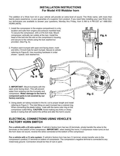
1. Install the compressor in the engine compartment in a dry<br />
location and safe from engine and exhaust manifold heat.<br />
To secure the compressor, drill a 3/16-inch hole. Mount<br />
compressor vertically (air outlets at the top). Install the<br />
head of the bolt into the slot on the compressor’s housing<br />
and secure to the vehicle using the lock washer/nut<br />
provided. (See Fig. A).<br />
2. Position each trumpet with open end facing down, mark<br />
and drill a 1/4-inch hole for each trumpet. Secure to vehicle<br />
referring to Figure B. Use mounting hardware in order<br />
shown - spacer, lock washer/nut.<br />
3. IMPORTANT: Mount trumpets with the<br />
open ends facing down. This will prevent<br />
water from entering into the trumpets and<br />
compressor. Water damage to the <strong>horn</strong>’s<br />
component parts is not covered by our<br />
factory warranty.<br />
4. Using plastic air tubing included in the kit, cut to proper length and install<br />
referring to Figure C. The inlet fitting on each trumpet has a colored ring.<br />
When connecting the plastic tubing , mate with the same color ring on the<br />
compressor outlet fitting. CAUTION: Avoid making any kinks or sharp<br />
bends in tubing that will restrict the airflow and alter the <strong>horn</strong>'s sound.<br />
ELECTRICAL CONNECTIONS USING VEHICLE’S<br />
FACTORY HORN SWITCH<br />
<strong>For</strong> a vehicle with a (2) wire system: If vehicle’s factory <strong>horn</strong> has two (2) terminals, simply transfer the wires to the<br />
terminals on the bottom of the compressor. IMPORTANT: when testing the <strong>horn</strong>s, if compressor motor turns on but<br />
the <strong>horn</strong> does not sound, reverse the wires connected at the bottom of the compressor.<br />
<strong>For</strong> a vehicle with a (1) wire system: If vehicle’s factory <strong>horn</strong> has two (1) terminal, simply transfer wire to the<br />
compressor’s positive (+) terminal on bottom of compressor. The compressor’s negative terminal is connected to any<br />
metal body ground. Connection should be free of rust or paint.
ELECTRICAL CONNECTIONS FOR A NEW HORN BUTTON SWITCH:<br />
Install the relay in a dry location with the terminals facing downward near the compressor. Refer to figure 4 for wiring.<br />
A. Connect relay terminal 87 to the positive terminal at the bottom of the compressor. Use no less than a 16-gauge<br />
wire.<br />
B. Connect relay terminal 85 to<br />
the <strong>horn</strong> switch terminal. The<br />
other <strong>horn</strong> switch terminal is<br />
connected to ground (body of<br />
vehicle). An 18-gauge wire is<br />
suggested for this connection.<br />
C. Connect relay terminals 30/86<br />
to positive (+) 12-volt battery,<br />
alternator or accessories. Use<br />
16-gauge or heavier wire. A<br />
20-ampere fuse is suggested<br />
to be installed as shown in<br />
Figure D.<br />
TOGGLE SWITCH<br />
<strong>INSTALLATION</strong><br />
The toggle switch, included in kit,<br />
will control the <strong>horn</strong>’s sounds. One<br />
position for a steady three trumpet sound and the other will<br />
produce a turkey sound.<br />
RECAP OF TERMINAL CONNECTIONS<br />
Terminals 30/86: the two (2) terminals are connected to 12-volt positive (+) using a fuse.<br />
Terminal 85: connect <strong>horn</strong> switch negative (-).<br />
Terminal 87: connect positive (+) terminal of compressor.<br />
1. Mount the toggle switch in an accessible location inside the<br />
Vehicle.<br />
2. Connect one terminal of the toggle switch to ground, any<br />
body bolt in the dashboard area. Make sure the surface is<br />
clean from dirt and rust so as to make a good<br />
electrical connection.<br />
3. Connect the other terminal of the toggle switch to the<br />
compressor’s minus (-) terminal on the side of the compressor<br />
using the black wire with the insulated terminal provided.<br />
4. Attach the red wire with the insulated terminal to the compressor’s<br />
positive (+) terminal on the side of the compressor. Splice the other end of the wire to the wire that is connected<br />
on the bottom of the compressor’s motor marked positive (+), as shown in Fig. E.<br />
Warranty<br />
Wolo Manufacturing Corporation (“Wolo”) warranties to the original purchaser, for three months from the date of purchase,<br />
that this product is free from defects in workmanship and materials. If there is such a proven defect, Wolo, at its option, will<br />
either repair or replace the item free of charge, if it is returned to Wolo within three months from the date of purchase<br />
together with proof of purchase as described below. Wolo reserves the right to inspect any defect prior to settling any<br />
warranty claim by repair or replacement. This warranty is limited as above provided and Wolo will not be responsible for fire<br />
or other casualty or accident, due to neglect, abuse, abnormal use, modifications, faulty installation of this product, or<br />
natural causes.<br />
ANY EXPRESSED WARRANTY NOT PROVIDED HEREIN IS EXCLUDED AND DISCLAIMED. THE IMPLIED WARRANTIES OF<br />
MERCHANTABILITYAND OF FITNESS FOR A PARTICULAR PURPOSE ARE EXPRESSLY LIMITED TO ATERM OF THREE (3)<br />
MONTHS. UNDER NO CIRCUMSTANCES SHALL WOLO BE LIABLE TO PURCHASER OR ANY OTHER PERSON FOR ANY<br />
SPECIAL OR CONSEQUENTIAL DAMAGES, WHETHER ARISING OUT OF BREACH OF WARRANTY OR OTHERWISE.<br />
To obtain warranty service, return the product prepaid, and include the original bill of sale showing the date of purchase. Provide<br />
with the return a brief description of the problem. Also, include with the return a check or money order in the amount of $10.00 to<br />
cover return shipping. Mail to:<br />
Wolo Manufacturing Corp. One Saxwood Street, Deer Park, NY<br />
11729 Attn: Warranty Service E-mail: tech@wolo-mfg.com<br />
© 2006 W olo Mfg. Corp All Rights<br />
Reserved.