Lathing & Plastering Specifications for
Lathing & Plastering Specifications for
Lathing & Plastering Specifications for

Create successful ePaper yourself
Turn your PDF publications into a flip-book with our unique Google optimized e-Paper software.
Technical<br />
In<strong>for</strong>mation<br />
PM14<br />
Product and Systems<br />
Technology<br />
<strong>Lathing</strong> and <strong>Plastering</strong> <strong>Specifications</strong><br />
<strong>for</strong> Handball and Racquetball Courts<br />
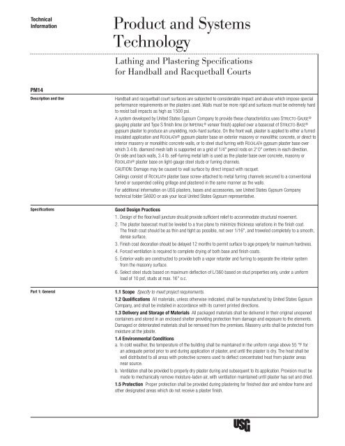
Description and Use Handball and racquetball court surfaces are subjected to considerable impact and abuse which impose special<br />
per<strong>for</strong>mance requirements on the plasters used. Walls must be more rigid and surfaces must be extremely hard<br />
to resist ball impacts as high as 1500 psi.<br />
A system developed by United States Gypsum Company to provide these characteristics uses Structo-GauGe ®<br />
gauging plaster and Type S finish lime (or ImperIal ® veneer finish) applied over a basecoat of Structo-BaSe ®<br />
gypsum plaster to produce an unyielding, rock-hard surface. On the front wall, plaster is applied to either a furred<br />
insulated application and rocklath ® gypsum plaster base on exterior masonry or monolithic concrete, or direct to<br />
interior masonry or monolithic concrete walls, or to steel stud furring with rocklath gypsum plaster base over<br />
which 3.4 lb. diamond mesh lath is supported on a grid of 1/4" pencil rods on 2' 0" centers in each direction.<br />
On side and back walls, 3.4 lb. self-furring metal lath is used as the plaster base over concrete, masonry or<br />
rocklath ® plaster base on light-gauge steel studs or furring channels.<br />
CAUTION: Damage may be caused to wall surface by direct impact with racquet.<br />
Ceilings consist of rocklath plaster base screw-attached to metal furring channels secured to a conventional<br />
furred or suspended ceiling grillage and plastered in the same manner as the walls.<br />
For additional in<strong>for</strong>mation on USG plasters, bases and accessories, see United States Gypsum Company<br />
technical folder SA920 or ask your local United States Gypsum representative.<br />
<strong>Specifications</strong> Good Design Practices<br />
1. Design of the floor/wall juncture should provide sufficient relief to accommodate structural movement.<br />
2. The plaster basecoat must be leveled to a true plane to minimize thickness variations in the finish coat.<br />
The finish coat should be as thin and tight as possible, not over 1/16", and troweled completely to a smooth,<br />
dense surface.<br />
3. Finish coat decoration should be delayed 12 months to permit surface to age properly <strong>for</strong> maximum hardness.<br />
4. Forced ventilation is required to complete drying of both base and finish coats.<br />
5. Exterior walls are constructed to provide both a vapor retarder and furring to separate the interior system<br />
from the masonry surface.<br />
6. Select steel studs based on maximum deflection of L/360 based on stud properties only, under a uni<strong>for</strong>m<br />
load of 10 psf, studs at max. 16" o.c.<br />
Part 1: General 1.1 Scope Specify to meet project requirements.<br />
1.2 Qualifications All materials, unless otherwise indicated, shall be manufactured by United States Gypsum<br />
Company, and shall be installed in accordance with its current printed directions.<br />
1.3 Delivery and Storage of Materials All packaged materials shall be delivered in their original unopened<br />
containers and stored in an enclosed shelter providing protection from damage and exposure to the elements.<br />
Damaged or deteriorated materials shall be removed from the premises. Masonry units shall be protected from<br />
moisture at the jobsite.<br />
1.4 Environmental Conditions<br />
a. In cold weather, the temperature of the building shall be maintained in the uni<strong>for</strong>m range above 55 °F <strong>for</strong><br />
an adequate period prior to and during application of plaster, and until the plaster is dry. The heat shall be<br />
well distributed to all areas with protective screens used to deflect concentrated heat from plaster areas<br />
near source.<br />
b. Ventilation shall be provided to properly dry plaster during and subsequent to its application. Provision must be<br />
made to mechanically remove moisture-laden air, with ventilation maintained until plaster has set and dried.<br />
1.5 Protection Proper protection shall be provided during plastering <strong>for</strong> finished door and window frame and<br />
other designated areas which do not receive a plaster finish.
Part 2: Products a. Masonry Plaster Base: (clay tile) (concrete block) (monolithic concrete) ( )" thick, properly cured or kiln-dried<br />
2.1 Materials b. Portland Cement: Type I, II, or III, complying with ASTM C150.<br />
c. Plaster Base: Regular rocklath gypsum plaster base, 3/8" thick, (3.4 lb. self-furring diamond mesh lath).<br />
d. Basecoat Plaster: Structo-BaSe gypsum plaster.<br />
e. Aggregate: Sand meeting ASTM C35 requirement <strong>for</strong> plaster, ASTM C144 <strong>for</strong> mortar.<br />
f. Water: Potable and not containing impurities that affect the setting of gypsum.<br />
g. Lime:<br />
1. Plaster—Type S finish<br />
2. Mortar—Regular or air-entraining mason’s lime, Type S.<br />
h. Gauging Plaster: Structo-GauGe.<br />
i. Finish Plaster: ImperIal veneer finish.<br />
j. Rein<strong>for</strong>cing Bars: 1/4" round, steel pencil rods.<br />
k. Rein<strong>for</strong>cing Bar Attachment Brackets: wall furring brackets.<br />
l. <strong>Lathing</strong> Channel: Cold-rolled channels, (3/4) (1-1/2) (2)".<br />
m. Furring: 7/8" metal furring channel; Z-furring channel (1) (2) (3)".<br />
n. Lath Attachment Clip: BrIdjoInt field clip B-1.<br />
o. Casing Bead: #66 casing bead, expanded flange.<br />
p. Tie Wire: (16) (18) ga.<br />
q. Fasteners: Steel screws, Climaseal-coated, 1" type S, 1" type S-12, 1/2" type S-12 low profile head.<br />
r. Insulation: Polystyrene (1) (2) (3)".<br />
s. Vapor Retarder: 4 mil. polyethylene.<br />
t. Steel Studs: Min. 20 ga.<br />
u. Runner Track: Min. 20 ga.<br />
v. USG Plaster Bonder<br />
2.2 Mixes a. Mortar—Portland cement-lime mortar—mix in a proportion of 1 bag (94 lb.) portland cement to 2 bags<br />
(100 lb.) mason’s lime to 9 cu. ft. of sand.<br />
b. Basecoat shall be mixed in the following proportions. For scratch coat—over rocklath, 2:1; over block,<br />
3:1. For brown coat—over rocklath, 2-1/2:1; over monolithic concrete, 21/2:1; over block, 3:1.<br />
c. Finish plaster shall be mixed in dry-weight proportions of 1:1 parts Type S lime to Structo-GauGe<br />
gauging plaster.<br />
d. Finish plaster (option): ImperIal veneer finish shall be mixed with water only per manufacturer’s directions.<br />
Part 3: Execution a. Erect masonry plaster base backup of clay tile, concrete block or monolithic poured concrete. Lay up<br />
3.1 Masonry Partition Backup<br />
masonry with a full mortar bed, full end joint and in running bond. Cut mortar joints flush with surface.<br />
Rein<strong>for</strong>ce horizontal joints at every third course.<br />
b. Erect concrete block or clay tile using portland cement-lime mortar.<br />
c. Coat clay tile or monolithic concrete interior wall surfaces with USG plaster bonder in a continuous film<br />
according to product directions. Remove all dirt, grease, wax, oil, efflorescence and parting compounds from<br />
monolithic concrete surfaces be<strong>for</strong>e applying a continuous application of USG plaster bonder.<br />
3.2 Steel Stud Interior Dividing Walls a. Fasten top and bottom runner tracks to structure with power-activated fasteners spaced 12" o.c. Set studs in<br />
runner tracks and space no more than 16" o.c. Fasten to bottom runners with 1/2" type S-12 low profile<br />
head screws, with one screw in each flange. Studs shall be cut 3/8" short to allow <strong>for</strong> deflection.<br />
b. Fasten 3/8" thick rocklath plaster base to studs with 1" type S-12 screws, four per stud.<br />
3.3 Exterior Masonry Walls a. Exterior building walls shall be waterproofed be<strong>for</strong>e installation of plaster system. Interior of exterior walls must<br />
be furred.<br />
b. Erect insulation vertically and hold in place with Z-furring channels spaced 16" o.c. Install channels over<br />
polyethylene vapor retarder; attach narrow flanges of channels to wall with concrete stub nails or power-<br />
driven fasteners spaced 24" o.c.<br />
c. Fasten 3/8" thick rocklath plaster base to Z-furring channels with 1" type S screws, three per stud. Use<br />
BrIdjoInt clips at end joints between channels.
3.4-lb selffurring<br />
diamond<br />
mesh<br />
metal lath<br />
Z-furring channel<br />
vapor retarder<br />
polystyrene<br />
insulation<br />
3 /8" ROCKLATH<br />
plaster base<br />
3.4-lb selffurring<br />
diamond<br />
mesh<br />
metal lath<br />
casing bead<br />
7 /8" plaster<br />
block or monolithic<br />
concrete wall<br />
36"<br />
(front) impact wall<br />
1 1 /4" plaster<br />
side wall 1<br />
play wall<br />
Interior uninsulated assemblies<br />
block or monolithic concrete wall<br />
casing bead<br />
7 /8" plaster<br />
2<br />
(front) impact wall<br />
1 1 /4" plaster<br />
side wall 5 play wall 6<br />
Exterior insulated assemblies<br />
ROCKLATH<br />
32"<br />
max. on Z-furring<br />
insulated system<br />
Wall-ceiling Intersections<br />
(uninsulated or insulated assemblies)<br />
adjustable wall<br />
furring bracket<br />
1 /4" diameter<br />
pencil rod<br />
grillage<br />
24" centers<br />
3.4-lb diamond<br />
mesh metal lath<br />
vapor retarder<br />
Z-furring channel<br />
polystyrene<br />
insulation<br />
adjustable wall<br />
furring bracket<br />
3 /8" ROCKLATH<br />
plaster base<br />
1 /4" diameter<br />
pencil rod<br />
grillage<br />
24" centers<br />
3.4-lb diamond<br />
mesh metal lath<br />
base at end and sidewalls base at impact wall<br />
3 /8" ROCKLATH<br />
plaster base<br />
assembly (same<br />
as front side)<br />
3 /8" ROCKLATH<br />
plaster base<br />
3.4-lb selffurring<br />
diamond<br />
mesh<br />
metal lath<br />
metal studs<br />
exterior sheathing<br />
cavity insulation<br />
vapor retarder<br />
3 /8" ROCKLATH<br />
plaster base<br />
3.4-lb selffurring<br />
diamond<br />
mesh<br />
metal lath<br />
casing bead<br />
7 /8" plaster<br />
(front) impact wall<br />
1 1 /4" plaster<br />
side wall 3 play wall 4<br />
Interior uninsulated assemblies<br />
casing bead<br />
7 /8" plaster<br />
(front) impact wall<br />
1 1 /4" plaster<br />
Exterior insulated assemblies<br />
32"<br />
max. on Z-furring<br />
insulated system<br />
32"<br />
max. on Z-furring<br />
insulated system<br />
side wall 7 play wall 8<br />
corner intersection<br />
metal studs<br />
3 /8" ROCKLATH<br />
plaster base assembly<br />
(same as front side)<br />
adjustable wall<br />
furring bracket<br />
3 /8" ROCKLATH<br />
plaster base<br />
1 /4" diameter<br />
pencil rod<br />
grillage<br />
24" centers<br />
3.4-lb diamond<br />
mesh metal lath<br />
metal studs<br />
exterior sheathing<br />
vapor retarder<br />
cavity insulation<br />
adjustable wall<br />
furring bracket<br />
3 /8" ROCKLATH<br />
plaster base<br />
1 /4" diameter<br />
pencil rod<br />
grillage<br />
24" centers<br />
3.4-lb diamond<br />
mesh metal lath
3.4 Grounds Set ground by means of mechanical beads or screed to provide minimum 1-1/4" thickness on front wall, 7/8"<br />
on side and back walls, 1/2" on ceilings.<br />
3.5 <strong>Lathing</strong> a. Front Wall—Provide rein<strong>for</strong>cing grid of 1/4" pencil rods spaced 24" o.c. each way, supported by adjustable<br />
wall furring brackets spaced 36" o.c. on masonry or concrete, and 32" on furred insulated and steel stud<br />
applications. Securely wire-tie 3.4 lb. diamond mesh lath to the grid, held 7/8" away from face of masonry or<br />
rocklath plaster base.<br />
b. Side and Back Walls—Lath with 3.4 lb. self-furring metal lath directly over concrete or masonry. Steel<br />
frame partition shall be lathed with rocklath plaster base and 3.4 lb. self-furring metal lath.<br />
c. Ceiling—Fasten 3/8" thick rocklath plaster base to furring channel with three 1" type S screws per<br />
channel. Add metal rein<strong>for</strong>cement at all corners of recessed light fixture openings or grilles. Staple<br />
12" x 24" metal lath rein<strong>for</strong>cement diagonally across corner openings.<br />
d. Internal Angles and Wall/Floor Juncture—Attach #66 casing bead to face of metal lath and coat bead<br />
with USG plaster bonder.<br />
3.6 Grouting Grout steel door and window frames in solid plaster be<strong>for</strong>e applying metal lath.<br />
3.7 Plaster Basecoat Application Mix basecoat plaster in a mechanical mixer to a uni<strong>for</strong>m consistency following manufacturer’s directions.<br />
Apply scratch coat, using sufficient pressure to <strong>for</strong>ce plaster through the metal rein<strong>for</strong>cement, and bond<br />
it to the masonry or rocklath plaster base without leaving voids. After scratch coat has set and partially<br />
dried, apply brown coat and screed to a true, level plane. Leave surface sufficiently rough to mechanically<br />
key finish coat.<br />
3.8 Finish Plaster Application Apply finish in as thin an application as possible to partially dry basecoat. Final thickness shall not exceed 1/16".<br />
Hand-finish troweling is required to smooth and densify surface. When ImperIal veneer finish is used, take care<br />
in joinings and with base application to ensure a smooth finished surface.<br />
3.9 Completion At completion of the finish plaster work, clean all plaster from exposed metal, leaving work ready <strong>for</strong> decoration<br />
by others at a later time. Remove all plaster rubbish, excess material, scaffolding, tools and other equipment<br />
from the building, leaving floors broom clean.<br />
Trademarks<br />
The following trademarks used herein<br />
are owned by United States Gypsum<br />
Company: ImperIal, rocklath, Structo-<br />
BaSe, Structo-GauGe, BIrdjoInt, uSG,<br />
uSG in stylized letters. Climaseal, Type S<br />
and Type S-12 are trademarks of ITW<br />
Buildex.<br />
Manufactured by<br />
United States Gypsum Company<br />
550 West Adams Street<br />
Chicago, IL 60661<br />
Note<br />
Products described here may not be<br />
available in all geographic markets. Consult<br />
your U.S. Gypsum Company sales office or<br />
representative <strong>for</strong> in<strong>for</strong>mation.<br />
800 USG.4YOU (874-4968)<br />
usg.com<br />
Notice<br />
We shall not be liable <strong>for</strong> incidental and<br />
consequential damages, directly or<br />
indirectly sustained, nor <strong>for</strong> any loss caused<br />
by application of these goods not in<br />
accordance with current printed instructions<br />
or <strong>for</strong> other than the intended use. Our<br />
liability is expressly limited to replacement<br />
of defective goods. Any claim shall be<br />
deemed waived unless made in writing to<br />
us within thirty (30) days from date it was<br />
or reasonably should have been discovered.<br />
Safety First!<br />
Follow good safety and industrial<br />
hygiene practices during handling and<br />
installing products and systems. Take<br />
necessary precautions and wear the<br />
appropriate personal protective<br />
equipment as needed. Read material<br />
safety data sheets and related literature<br />
on products be<strong>for</strong>e specification and/or<br />
installation.<br />
PM14/rev. 10-10<br />
© 2010, United States Gypsum Company.<br />
Printed in U.S.A.