Building instructions Fournier RF-4D - Aero-naut
Building instructions Fournier RF-4D - Aero-naut
Building instructions Fournier RF-4D - Aero-naut

Create successful ePaper yourself
Turn your PDF publications into a flip-book with our unique Google optimized e-Paper software.
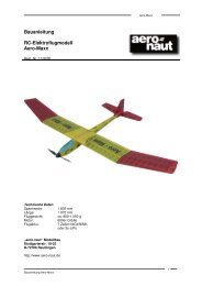
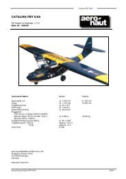
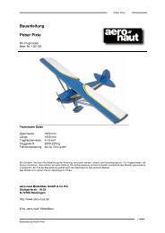
<strong>Building</strong> <strong>instructions</strong><br />
<strong>Fournier</strong> <strong>RF</strong>-<strong>4D</strong><br />
Scale 1:4<br />
RC model aircraft<br />
Order No. 1355/00<br />
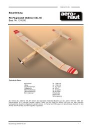
Specification<br />
Wingspan: approx. 2815 mm<br />
Length: approx. 1510 mm<br />
Wing area: approx. 71.6 dm 2<br />
Tailplane area: approx. 11.7 dm 2<br />
Geometrical aspect ratio: approx. 11.06<br />
Total surface area: approx. 83.3 dm 2<br />
All-up weight: approx. 4700 – 5000 g<br />
Wing loading: approx. 65.5 – 69.8 g/dm 2<br />
Wing section, root: <strong>Aero</strong><strong>naut</strong>, 14.5 % thick<br />
Wing section, tip: <strong>Aero</strong><strong>naut</strong>, 12 % thick<br />
Tailplane section: Selig-Donovan SD8020, mod. 11 %<br />
RC functions:<br />
- Ailerons<br />
- Elevator<br />
- Rudder<br />
- Throttle<br />
- Airbrakes<br />
- Retractable wheel<br />
Replacement parts<br />
GRP fuselage: Order No. 1355/02<br />
GRP cowl: 1355/03<br />
Canopy: 1355/04<br />
Pair wing panels – styrofoam + obechi: 1355/05<br />
Tailplane – styrofoam + balsa: 1355/09<br />
aero-<strong>naut</strong> Modellbau GmbH & Co. KG<br />
Stuttgarterstr. 18-22<br />
D-72766 Reutlingen<br />
Germany<br />
http://www.aero-<strong>naut</strong>.de
<strong>Fournier</strong> <strong>RF</strong>-<strong>4D</strong> building <strong>instructions</strong><br />
<strong>Fournier</strong> <strong>RF</strong>-<strong>4D</strong><br />
Power system<br />
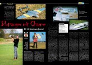
Our <strong>RF</strong>-<strong>4D</strong> is an excellent choice for electric power thanks to its efficient aerodynamic design in general, and<br />
its wing loading and high aspect ratio in particular.<br />
Power system for 16 cells<br />
actro 24-4 Order No. 7002/14<br />
13.5 x 7" propeller 7234/60<br />
or 14 x 7" 7234/64<br />
or 14 x 8" 7234/68<br />
actronic 40-18 speed controller 7002/52<br />
actro 24-5 Order No. 7002/15<br />
14 x 8" propeller 7234/68<br />
or 14 x 9" 7234/67<br />
Actro hub, 35 mm / M8 7002/65<br />
actronic 40-18 speed controller 7002/52<br />
We strongly recommend that you install the motor using our rubber buffers, Order No. 7002/75.<br />
The flight battery should take the form of two packs (2 x 8 cells). The packs must be installed projecting into<br />
the motor compartment (cowl) in order to obtain the correct C.G. (balance point).<br />
Glowplug motors<br />
An appropriate engine sound is an important factor in the full experience of flying any powered model<br />
aircraft. Certainly with scale models a completely non-scale sound should be avoided, otherwise the overall<br />
image is spoiled. In short - the <strong>RF</strong>-<strong>4D</strong> deserves a four-stroke motor.<br />
We recommend the use of our motor mount 7153.11 with rubber buffers, which will accept all the<br />
recommended single-cylinder motors. This mount reduces the transmission of motor vibration to the<br />
airframe, and thereby reduces the noise emitted by the airframe itself.<br />
The 9.1 cc Saito FA-56 provides plenty of power for realistic scale flying, but any Saito motor from the FA 56<br />
to the 15 cc FA 91S will fit. Of course, the perfect choice would be an opposed twin such as the 15 cc Saito<br />
FA-90TS or the 16.4 cc FA-100T.<br />
To increase power system reliability we recommend that you fit an on-board glowplug regulator; there are<br />
plenty available commercially. These units also offer an additional advantage: they eliminate the need for a<br />
separate glowplug battery for starting, together with the ugly hole for the plug clip.<br />
Incidentally - all the motors mentioned above disappear completely under the cowl.<br />
Description of retractable wheel<br />
The plan shows all the parts of the system in schematic form, including the connecting hoses.<br />
In the “wheel down” position the system is not under pressure, and the coil spring installed in the air cylinder<br />
moves the piston (= retract) to its end-point, and compressed air is released through the control valve. The<br />
cam disc mounted on the servo does not exert pressure on the control valve in this position.<br />
“Wheel retracted”: the cam disc operates the control valve, opening the path for the compressed air from the<br />
air tank to the control valve, pressure reducer and air cylinder. The piston runs to its end-point (against the<br />
pressure of the coil spring); the piston rod retracts the wheel.<br />
The purpose of the pressure reducer is to adjust the transit time for retraction and extension to simulate<br />
scale speed.<br />
The only extra item that has to be purchased is the air pump (we recommend the Robart unit). The system<br />
adaptor for connecting the pump to the model’s compressed air system is included with the retract unit.<br />
The wheel door guides (15) serve to ensure that the doors (10) open and close at the correct time.<br />
2
<strong>Fournier</strong> <strong>RF</strong>-<strong>4D</strong> building <strong>instructions</strong><br />
<strong>Fournier</strong> <strong>RF</strong>-<strong>4D</strong><br />
Preparation<br />
The wooden parts are drawn to reduced scale in these building <strong>instructions</strong>; write the part number on each<br />
component with a soft pencil, using the drawing as a guide. Remove the parts from the die-cut sheets using<br />
a balsa knife where necessary. Check all parts for proper fit before installing them.<br />
If you are an experienced builder you may wish to alter the sequence described in these building<br />
<strong>instructions</strong>, but please think through the results of such changes.<br />
The building <strong>instructions</strong>, photographs, parts list, motor, retract unit and servos should be used constantly as<br />
aids to building. Note that the receiver and glowplug battery must be installed in the nose section.<br />
Before starting construction sand the surfaces of all the GRP parts thoroughly using 400-grit wet-and-dry<br />
abrasive paper. Make good any minor defects in the moulding using polyester filler paste, and finish off the<br />
edges of the cockpit area using the marked lines and photos as a guide.<br />
Important! the original machine was of wood construction, whereas our model features a moulded GRP<br />
fuselage. It is therefore important to keep the weight of the model’s tail end to an absolute minimum during<br />
construction. Items such as the receiver battery and similar must be installed as far forward as possible in<br />
the fuselage. You will almost certainly need to add nose ballast, especially if you fit a single-cylinder motor.<br />
Adhesives:<br />
Since the parts contained in the kit are very highly pre-fabricated, this section only calls for a few tips<br />
regarding the use of epoxy laminating resin. Compared to quick-setting epoxy glues this resin offers<br />
important advantages: it can be applied more accurately to the actual glued joint; it also penetrates into the<br />
narrowest of gaps, ensuring that joints are really strong. For some processes the resin should be thickened<br />
with a thixotropic agent; in this form it can be applied in exactly the right location, with no tendency to run off.<br />
Use coarse abrasive paper to roughen all areas of the fuselage which are to be glued. This is the only way to<br />
ensure that glued joints are really strong and durable.<br />
Construction starts with trimming the motor bulkhead (77) to fit in the fuselage - just sand the bottom edge to<br />
a slight bevel to match the curvature of the fuselage. The position of the motor crankshaft axis is shown on<br />
the plan. Be sure to mark the axes clearly on part (77).<br />
Cut a piece 195 mm long from the wing joiner sleeve (2) and fit it in the appropriate holes in the fuselage.<br />
Sand the outside of the sleeve if necessary, as it must not be a tight fit in the holes (risk of deforming the<br />
fuselage). Tack it in place with thin cyano, then reinforce the joints with laminating resin.<br />
Cut the opening for the wheel doors in the bottom of the fuselage. Take care - the front edge must be wider<br />
than the rear to match the shape of the wheel doors (10), which are not symmetrical.<br />
Place the retract unit centrally on the retract unit support (3) and align it carefully. Drill 4 mm Ø holes as<br />
required. Fit the support (3) through the bottom opening in the fuselage in front of the joiner sleeve (2) as<br />
shown in Fig. 2, and raise it into position. The sides of part (3) must be trimmed so that it fits against the<br />
joiner sleeve (2) as shown; use a pencil to mark where it has to be trimmed back, trim it, then offer it up<br />
again until it fits as described.<br />
The retract support (3) now has to be soaked in laminating resin. Apply the resin repeatedly to the trimmed<br />
periphery; the plywood will absorb the resin. Finally apply more resin to both sides of part (3) and allow it to<br />
cure fully. The retract unit can now be screwed to the support, and a fillet of thickened epoxy applied round<br />
the retaining nuts. Roughen the joint surfaces of the retract support and place it in the fuselage.<br />
With the retract unit and part (3) in the fuselage, set it to the “retracted” position. Cut a spacer about 2.5 mm<br />
thick (e.g. balsa) to size, place it on the bottom of the fuselage and slide it under the wheel; this ensures that<br />
there is a little clearance between the retracted wheel and the closed wheel doors (10). Position the retract<br />
unit support (3) in the fuselage and tack it in place with cyano. Remove the retract unit again and apply<br />
plenty of thickened epoxy to the joints. Fig. 4 shows a method which ensures good contact between the<br />
parts and the flat fuselage bottom.<br />
Gluing the wing joiner sleeves (2) in the wings: cut the remainder of part (2) in half and slide the sleeves<br />
into the wing panels. The sleeves must not project beyond the root ribs; shorten them slightly if necessary.<br />
Seal one end of each sleeve with a piece of balsa about 8 - 10 mm thick. The sleeves must be sealed<br />
3
<strong>Fournier</strong> <strong>RF</strong>-<strong>4D</strong> building <strong>instructions</strong><br />
<strong>Fournier</strong> <strong>RF</strong>-<strong>4D</strong><br />
completely, otherwise the PU adhesive might be forced inside them - this would be catastrophic! Please blow<br />
into the sleeves to check that they are sealed. Sand the sealed end of the sleeve to a taper over a length of<br />
about 5 mm, as this helps to distribute the adhesive when it is applied to the hole. Roughen the surface of<br />
the sleeve thoroughly using abrasive paper.<br />
The model can now be assembled “dry” (without glue). The wing dihedral should be 4° on each side,<br />
measured at the underside of the wing; this corresponds to 90 mm of packing under each wingtip. When the<br />
fuselage is resting on its skid, the packing should be about 100 mm high on each side.<br />
The next stage is to glue the joiner sleeves in the wings using PU adhesive, but the material is very difficult<br />
to remove, so certain protective measures are necessary. Apply Sellotape or similar to the root wing fairings<br />
of the fuselage, and cut through the openings neatly using a sharp balsa knife. Wipe Vaseline over the joiner<br />
tube (66), the inside of the joiner sleeves (inside only!), and the wing panel root ribs.<br />
Apply PU adhesive to the entire surface of the hole in each wing root using a length of hardwood dowel<br />
(approx. 5 - 6 mm Ø, 200 mm long); use a torch to check glue distribution. Apply a light coating of adhesive<br />
to the joiner sleeve (2). Spray a light mist of water into the hole in the wing and allow any excess water to run<br />
out again. Fit the joiner tube in the fuselage and slide one joiner sleeve onto it. Carefully slide the wing onto<br />
the joiner sleeve, working slowly and carefully. Remove excess PU adhesive as it is squeezed out, until the<br />
wing is resting against the fuselage root fairing.<br />
Now fix the wing to the fuselage thoroughly using adhesive tape, applied all round the root joint. Repeat the<br />
procedure with the second wing panel, then place the model in the established position and pack up the<br />
wingtips to the correct height.<br />
Important: the pot-life (working time) of the PU adhesive is about 30 - 45 minutes after application (i.e. after<br />
exposure to humidity). Initially the consistency of the adhesive is similar to honey, but humidity causes it to<br />
foam up and start to harden. At 20°C the adhesive sets in two hours; it reaches full strength in 24 hours.<br />
In an enclosed space the foaming action generates considerable pressure, and this is quite sufficient to push<br />
the wings away from the fuselage. Check the joints constantly for a period of at least an hour.<br />
The plywood air cylinder plate (6) bears a marking which denotes the centre of the holder for the retract air<br />
cylinder. Fix the holder to the plate using three M2.5 x 16 countersunk screws and nuts and fit the cylinder in<br />
the holder. Connect the air cylinder (5) to the retract unit as shown in Fig. 3, then re-install the assembly.<br />
Important: set the retract unit to the “extended” position (the air cylinder is under zero pressure in the “wheel<br />
down” position). Roughen the fuselage side and glue the air cylinder plate (6) in place as follows, facing foreand<br />
aft: first press the plate in position and run a pencil round it along the fuselage side, then drill a 2.2 mm<br />
Ø hole in the centre of the marked area. Apply adhesive tape to the outside of the fuselage to protect it.<br />
The plate (6) should now be held to the fuselage side from the outside using a 2.2 mm Ø self-tapping screw.<br />
To avoid the screw pulling the fuselage out of shape, cut a flat piece of 5 mm plywood about 100 x 50 mm in<br />
size, drill a 2.5 mm Ø hole in it and place it against the outside of the fuselage. Apply thickened epoxy to the<br />
plywood plate (6), position it carefully and fit the self-tapping screw into the plate from the outside. Don’t<br />
over-tighten the screw or you could distort the fuselage. Allow the epoxy to set hard, then remove the retract<br />
unit and air cylinder again.<br />
Now we turn to the motor mount. The <strong>instructions</strong> supplied with the mount describe in detail how to set the<br />
correct “hardness” to suit the motor you are using. In its standard form the motor / motor mount assembly<br />
may not fit under the cowl; to make the assembly as narrow as possible remove both “L”-section rails and<br />
remove about 3 mm from them. Fig. 6 shows how the rails are attached to the outriggers - see also Fig. 7.<br />
On the plan the overall length of the motor assembly to the front face of the propeller driver is stated as 130<br />
mm - please keep strictly to this. The motor and motor mount have no “visible” downthrust, but the geometry<br />
of the wing and tailplane produces an effective downthrust angle of about -2°. The tailplane is set at positive<br />
incidence, with the effect that the model flies tail-high - like the full-size machine.<br />
The original prototype was powered by a Saito FA-100T, and for this reason some of the photos exhibit<br />
obvious discrepancies compared to these <strong>instructions</strong> - please don’t let this confuse you. Both carburettors<br />
of this engine are mounted on top of the crankcase, so the fueltank has to be mounted higher than normal.<br />
The motor is also extremely short, so a plywood box has to be constructed, and this houses part of the<br />
4
<strong>Fournier</strong> <strong>RF</strong>-<strong>4D</strong> building <strong>instructions</strong><br />
<strong>Fournier</strong> <strong>RF</strong>-<strong>4D</strong><br />
fueltank. With this installation the throttle servo has to be installed on the left-hand side of the fuselage. If you<br />
install a single-cylinder motor “side-winder” style, the servo will be mounted on the right-hand side.<br />
Back to the standard version; installation of a single-cylinder motor. Remove the machined inside section<br />
from the motor bulkhead; the two circular stiffening plates are parts (64). Fig. 5 shows the motor bulkhead<br />
with an extension to accommodate the fueltank (see above) to suit the Saito FA-100T. The plywood<br />
bulkhead (77) must be soaked thoroughly in laminating resin; see above re. part (3). When the epoxy has<br />
cured, fix the motor to the motor mount, position it as accurately as possible and drill the 5 mm Ø holes.<br />
Remove the motor mount and open up the holes to 6.5 mm Ø to accept the captive nuts supplied. Install the<br />
motor mount and motor and check that it is correctly positioned. Check also the distance to the front face of<br />
the propeller driver. The holes for the fuel system tubes and throttle linkage sleeve can now be drilled.<br />
To prevent oil and dirt entering the fuselage, the front face of the fuselage (= motor bulkhead) should be<br />
closed off using one of the plywood plates (54). Lay the motor bulkhead on part (54) and mark the holes on it<br />
from the bulkhead (77). Fit the M5 mounting screws through the holes. Now mark the outline of the bulkhead<br />
(77) on part (54) and saw it to size. Soak part (54) with resin to prevent it absorbing fuel.<br />
Figs. 8 and 9 show the retract unit and air cylinder installed.<br />
Cut out the mudguard (35) using tin-snips, leaving a strip about 7 mm wide on both sides. Cut a slot in the<br />
side of the moulding to clear the actuating shaft of the retract unit. Cut the two parts (36) (15 - 20 mm long)<br />
from hardwood strip and glue them to the side strips at the bottom; 2.2 Ø x 6.5 mm self-tapping screws are<br />
fitted into these parts to attach the mudguard (35) to the fuselage floor. Fig. 38 shows approximately where<br />
the screws should be fitted in order to coincide with the blocks. Fig. 29 shows the mudguard and fueltank,<br />
which in this case is positioned to suit the Saito FA-100T.<br />
The co-ordinates for the screws should now be marked as accurately as possible on the fuselage bottom<br />
using the mudguard as a template. Drill the holes 2.3 mm Ø. Place the mudguard in the fuselage (retract unit<br />
installed), drill the first 1.5 mm Ø hole and fit a screw to secure it. Carefully drill the remaining holes, taking<br />
care not to deform the moulding. The mudguard must be located centrally in the fuselage.<br />
Figs. 10, 11 and 12 shows the plastic cockpit components. Please take a close look at Fig. 12, which shows<br />
how the instrument panel has to be trimmed (the side areas are located in the fuselage recess).<br />
Fig. 13 shows the hinge and actuating system of the wheel well doors (10). Important: the doors are not<br />
symmetrical in the fore-and-aft direction. Align them carefully, and mark the front end. Bend the final 20 mm<br />
of the mild steel rods (11) at right-angles. Cut two pieces 78 mm long from the brass tube (12) and file a<br />
notch in the centre of each using a round file (lubricating point). Slip the tubes onto the steel rods (11). The<br />
second bend at the front end of parts (11) should be located about 145 mm from the rear bend. Important:<br />
this bend must be located about 8 - 10 mm forward of the front face of the mudguard. Don’t forget: these<br />
parts are “handed”, i.e. there are left-hand and right-hand hinge assemblies.<br />
Cut two pieces 15 mm long from part (13), fix them to the formed rods (11) with soft binding wire and solder<br />
the parts together as shown in the photos and on the plan.<br />
Detail “X” on the plan shows a cross-section through the hinge system for the wheel doors (10) on the<br />
bottom of the fuselage. Note that the inside of parts (10) must be flush with the fuselage floor where the<br />
brass bush (12) is located. The entire hinge / actuation system can now be glued to the wheel doors (10).<br />
Place a piece of 1.5 mm plywood between the tongues of parts (10) and lay the brass tube on the spacer;<br />
the shaft (part 11) should have about 0.5 mm clearance above the tongues, i.e. the wall thickness of parts<br />
(12). Position the parts as accurately as possible (the dimensions are stated in detail “X”), and glue them in<br />
place using plenty of thickened laminating resin.<br />
Fig. 14 shows all the servo mounts. Please note that the elevators are actuated using two micro-servos, as<br />
this arrangement allows the snake outers to be glued directly to the fuselage sides. Install a high-quality<br />
mini-servo for the rudder. The throttle servo should be mounted on the right-hand side of the fuselage for a<br />
single-cylinder motor. Figs. 15 - 18 also show how the servos are installed. Position the mounts in the<br />
fuselage, tack them in place with cyano, then reinforce the joints with laminating resin.<br />
The next step is to install the “snakes” in the fuselage; start by drilling the exit holes in the fuselage. File<br />
these out at a very flat angle to avoid kinking the snake inners (40). Fit an M2 nut and clevis (71) on each<br />
threaded coupler, slip them through the fuselage interior and out of the appropriate exit holes, then connect<br />
5
<strong>Fournier</strong> <strong>RF</strong>-<strong>4D</strong> building <strong>instructions</strong><br />
<strong>Fournier</strong> <strong>RF</strong>-<strong>4D</strong><br />
the clevises to the servo output arms. Slip the snake outers (39) onto parts (40) from the tail end. Align the<br />
projecting outer sleeves as shown on the plan (inside the fuselage they must run in smooth curves), press<br />
them against the fuselage and tack them in place using cyano. Secure each snake outer at three points with<br />
cyano, then apply thickened epoxy at each point, preferably with a patch of glass cloth. Withdraw the inner<br />
tubes and slice off the excess outer sleeves (39) using a sharp chisel. The remainder of the snakes is used<br />
for the throttle linkage.<br />
Next comes the air exit - Fig. 20 and the plan tell you all you need to know here.<br />
Cut ten pieces about 15 mm long from the limewood strip (42) and glue them round the outside of the<br />
opening in the fuselage floor, spaced out evenly as shown in Fig. 24. These blocks support the 2.2 Ø x 6.5<br />
mm self-tapping screws which retain the hatch cover (54). We recommend that you tack the pieces in place<br />
with cyano, then run 1 - 2 drops of laminating resin into each joint.<br />
Section B-B on the plan shows the method of simulating the stiffeners of the full-size aircraft. Sand the<br />
spruce strip (7) to a slight angle, tack in place with cyano then reinforce the joints with laminating resin.<br />
Figs. 21 - 23 show the installation of the pneumatic control valve and its servo on the cockpit floor (26). Fig.<br />
21 shows the wheel extended, Fig. 22 the wheel retracted. Fig. 24 shows the transverse strip (36) on which<br />
the cockpit floor rests; see also the fuselage side elevation and the drawing of the servos on the left-hand<br />
fuselage side.<br />
The method of mounting the air tank is shown in section B-B, the side elevation and Fig. 26. We recommend<br />
that you make up two supports as shown in section C-C and secure the tank using Velcro (hook-and-loop)<br />
tape. Caution: apply a coat of laminating resin to the surface under the Velcro to obtain a strong bond. Glue<br />
the whole assembly in place using laminating resin.<br />
Carefully position the wheel well doors (10) inside the fuselage and tape them in place. Glue the brass tubes<br />
(12) in place with a fillet of thickened laminating resin. Take care: they must be very free-moving, otherwise<br />
you may end up with a belly-landing!<br />
Bend the return springs to follow the shape of the fuselage bottom and fit them into the brass tube guides<br />
(13). Tack them to the fuselage floor with cyano, then reinforce the joints. The photo also shows an<br />
alternative method.<br />
Fig. 31 shows the bottom fuselage hatch with the filler and one-way valve and a latch at the front. This hatch<br />
provides access to the wing retainer. The hatch is supplemented by a second opening which gives access to<br />
the receiver battery for recharging.<br />
Now it is time to make the cockpit rather more comfortable for the pilot. Single-sided foam pads are an<br />
excellent means of simulating the padding: use pads 5 mm thick for the sides and 3 mm thick for the pilot’s<br />
seat. Apply 50 mm wide double-sided carpet tape to the second side of the pad. The pads are covered in<br />
fabric; the choice of fabric is important - it must be pliable.<br />
Cut two strips 210 x 50 mm from the sheet for the side padding, and apply carpet tape to them. Lay the<br />
fabric flat, and align it perfectly “square”. Place the foam strips and carpet tape on the fabric and press them<br />
together. Now cut the fabric slightly oversize. Peel off the backing film from the edges of the foam tape, and<br />
press the strip against the table using a ruler or similar. Raise the excess fabric with a second ruler and<br />
press it onto the exposed adhesive layer. This way the edge stays neat and straight - see Figs. 36 and 37.<br />
The next stage is to assemble the parts permanently, but not until you have painted the cockpit area. Note<br />
that the top edge of the padding should be about 15 mm below the top of the cockpit flange.<br />
Figs. 32 to 35 show the method of making the seat padding. This presents absolutely no problems - the first<br />
phase is simply a repeat of the procedure already described. Apply UHU Greenit Kompakt-Kraft contact<br />
adhesive to the side parts and press the excess fabric against the sides with your fingers, holding it under<br />
slight tension. Cut off the excess with a small pair of scissors, apply the adhesive to the inside of the edges<br />
and pull the fabric over. Job done.<br />
The seat is simply held in the cockpit with Velcro: stick the in-fill panels (32) to (34) in place and apply resin<br />
to the faces before applying the Velcro.<br />
6
<strong>Fournier</strong> <strong>RF</strong>-<strong>4D</strong> building <strong>instructions</strong><br />
<strong>Fournier</strong> <strong>RF</strong>-<strong>4D</strong><br />
Cut pieces of aluminium tubing (44) about 5 mm long and press them into the GRP rudder hinge lugs (43).<br />
Trim the slots for the hinge lugs (43) in the tail post and insert them. Take a length of 3 mm Ø steel rod as a<br />
temporary rudder hinge shaft and slide it through the lugs: fit a 2 mm thick spacer (e.g. part 48) between the<br />
trailing edge of the fin and the shaft at the top, and a 3 mm plywood spacer at the bottom. Align the shaft as<br />
accurately as possible (it must be central) and tack parts (43) to the tail post with cyano. Glue the sleeves in<br />
the lugs at the same time - see Fig. 43. Apply a drop of laminating resin to each joint for reinforcement.<br />
Cut four parts from the aluminium tube (44) as shown in Figs. 44 and 45; the bottom piece should project<br />
slightly below the line of the fuselage. Press the rudder (46) against the fin to mark the position of the hinge<br />
lugs (43), and cut the slots for them using a balsa knife - Fig. 46. It should be possible for the whole length of<br />
the rudder leading edge to rest against the tube (44). Fig. 47 shows how the rudder is aligned with the fin.<br />
Position the rudder as accurately as you can, then tack the four pieces of tubing (44) to it using cyano.<br />
Reinforce the joints in the usual way, but not before removing the shaft and rudder - see Fig. 48.<br />
Divide the rudder leading edge (47) as shown in Fig. 49, and cut small recesses to clear the pieces of tube<br />
(44) glued in the hinge lugs (43). Determine the length of the leading edge sections (47) from the rudder<br />
itself, and glue the pieces to the front face of the rudder.<br />
The rudder leading edge should be 8 mm thick at the top, but full thickness (12 mm) at the bottom. Round off<br />
the leading edge step by step as shown in sections D-D and E-E on the plan. The gap between fin and<br />
rudder should be narrow and even, but must permit rudder travels of at least +/- 30° - see Figs. 50 and 51.<br />
Cut a slot for the tailskid actuator (48) using a fine-bladed fretsaw - see fuselage side elevation and section<br />
E-E. File a notch in the front edge of part (48) if necessary to avoid obstructing the rudder hinge shaft (44).<br />
Cut a slot for the rudder horn, but don’t glue it in place until the rudder has been covered; the same applies<br />
to all the control surface horns. Important: all horns (5 off) must be roughened with coarse abrasive paper<br />
before gluing them in their slots. Drill out the linkage holes to 1.6 mm Ø beforehand to accept the clevis pins.<br />
For the tailskid bush (machined aluminium part) drill an 8 mm Ø hole about 48 - 50 mm forward of the tail<br />
end of the fuselage. The coil springs (56) must be installed under light tension. Roughen the bush and degrease<br />
it before fixing it in place with plenty of epoxy.<br />
The fuselage is now almost complete, and we can turn to the fuel supply. If the usual rules are followed<br />
(carburettor level with centreline of fueltank) the usable space for the tank is somewhat restricted. If you wish<br />
to install the tank above the mudguard, it should be of a very low-profile type; a very good choice is the<br />
Simprop “square” type of 340 cc capacity. It has to be located slightly higher than the ideal position, but with<br />
a single-cylinder four-stroke mounted side-winder the carburettor is fairly high in any case - an acceptable<br />
solution.<br />
If you wish to carry more fuel than that, two smaller tanks can be connected in series, as shown on the plan.<br />
In this case you can also set the “ideal” installation height for the actual motor you are using. Important: the<br />
filler / drain line for the system must be sealed for flying (e.g. by fitting an M3 x 10 mm screw in the end).<br />
Oval fueltanks of 240 cc capacity are ideal for the twin-tank arrangement.<br />
The two tailplane panels are glued to the fuselage using a pair of CFRP joiner tubes (60). First cut the tube<br />
(60) in two as shown on the plan, and check that the tubes are an easy sliding fit in the fuselage. Trim the<br />
holes if necessary.<br />
We recommend the following method of gluing the joiner tubes (60) in the fin:<br />
- Apply adhesive tape over the moulded-in tailplane root fairings and apply a coat of mould-release wax to<br />
the tape. Open up the holes using a sharp balsa knife.<br />
- Glue pieces of balsa in both ends of the tubes (60) to seal them.<br />
- The front joiner tube (60) should now be glued in (say) the left-hand tailplane panel, the rear tube in the<br />
right-hand panel using thickened laminating resin. This is the procedure:<br />
- Apply plenty of epoxy to the inside of the holes and distribute it carefully using a length of dowel or steel<br />
rod. Slowly push the tube into the hole, twisting it to and fro as you do so. Watch the depth! If no epoxy is<br />
squeezed out of the root rib, apply more epoxy. Remove excess resin then clean any excess epoxy from<br />
the tube using acetone.<br />
- Now leave the epoxy to semi-harden; the time this takes depends on the room temperature. The tubes<br />
should now be slightly difficult to move. At this point fit both tailplane panels into the fuselage, align them<br />
7
<strong>Fournier</strong> <strong>RF</strong>-<strong>4D</strong> building <strong>instructions</strong><br />
<strong>Fournier</strong> <strong>RF</strong>-<strong>4D</strong><br />
carefully and leave the epoxy to cure fully. When the epoxy is hard, withdraw the parts from the fuselage<br />
and - if necessary - trim the tailplane panels to match the root fairings on the fuselage.<br />
- The tailplane panels should not be installed permanently until the fuselage has been painted and the<br />
tailplane covered.<br />
You have already rubbed down the fuselage, but it must now be thoroughly de-greased before painting. An<br />
excellent method is to wash it using water with liquid detergent added. Wipe the entire surface with a wet<br />
cloth to remove grease, then rinse it more using clean water. Seal all the fuselage openings beforehand.<br />
Our <strong>RF</strong>-<strong>4D</strong> was sprayed with a base coat of Orapaint and sealed with Orapaint EKS clear lacquer (gloss<br />
finish). A highly convincing finish is obtained if you thin the clear lacquer very greatly (approx. 300%<br />
thinners).<br />
Installing the tailplane is now extremely simple: first roughen the joint surface of the integral root fairings<br />
using coarse abrasive paper. Apply sufficient thickened epoxy to the holes in the tailplane panels and<br />
distribute it evenly. Apply the same epoxy mixture to the root face of the tailplane panels. Apply a thin<br />
coating of epoxy to the joiner tubes (60) (already bonded-in) and slide them through the fuselage. Remove<br />
excess resin with a paper towel and clean the surfaces with petrol. Apply a few drops of epoxy to the inside<br />
joints between fuselage and joiner tubes, working through the openings in the tail post.<br />
When the resin has started to cure, press the parts together finally, clean the area once more and tape the<br />
tailplane panels to the fuselage.<br />
Now it’s the rudder’s turn: apply Vaseline to all parts of the hinge system, and only then fit the hinge shaft<br />
(45). Secure the shaft at the bottom.<br />
Thread the coil springs (56) into the tailskid actuator (48) and connect the other end to the lever on the<br />
tailskid. Apply a drop of thread-lock fluid to the threaded part of the tailskid retaining screw. Now place the<br />
coil springs under light tension, fit the screw in the actuator and tighten it. Apply a drop of oil for lubrication.<br />
After covering the elevator panels, glue the elevator horns (49) in the slots and attach the panels to the<br />
tailplane using the hinges (61). Grease the snake inners lightly and slide them into the outer sleeves from the<br />
front end. Connect the inners to the servo output arms. Connect clevises and threaded couplers to the<br />
elevator horns and establish the correct length of the snake inners (servos and elevators neutral / central).<br />
Cut off excess pushrod length and crimp the threaded couplers firmly onto the pushrods.<br />
The fuselage and cockpit can now be fitted out permanently. Important: before fitting the mudguard check<br />
the operation of the retract system carefully. It is important that the wheel doors work reliably every time.<br />
To install the retract unit we recommend a right-angled 3 mm A/F ball-end allen driver at least 125 mm long.<br />
This tool makes it relatively easy to reach the retract unit retaining screws through the opening in the motor<br />
bulkhead. Tighten the screws really firmly, and check again that they are really tight. Install the air cylinder<br />
and ensure that the control pin of the retract unit reaches the end-point of its guide. If not, adjust the clevis<br />
until it does. Tighten the actuating arm really thoroughly on its shaft.<br />
The air lines can now be connected: fit the hoses full-depth onto the nipples; this is easier if you first soften<br />
the hose slightly with heat from a match. Tighten the grubscrew in the pressure reducer until it is about 0.5 -<br />
1 mm below the surface of the body. The retraction time should be set to about two seconds. Pressurise the<br />
system - it is not necessary to set a pressure higher than 6 bar.<br />
Completing the wings starts with gluing the incidence tubes (67) in the root ribs: saw two pieces about 25<br />
mm long from the brass tube (67), and seal one end of each. Check that the tubes are an easy sliding fit in<br />
the holes in the fuselage root fairings. Fit the wing joiner tube through the fuselage and provisionally plug in<br />
the wings. Check that the trailing edge of the wings and the root fairings line up correctly. If necessary adjust<br />
the hole in the root rib. Apply thickened epoxy to the hole in the root rib, press the tubular incidence peg into<br />
it and wipe off excess resin. Allow the epoxy to harden slightly, then clean any resin residues from the tube<br />
using acetone and apply mould-release wax to it. Now push the wing against the fuselage as far as it will go<br />
and check that the end of the incidence tube does actually protrude inside the fuselage. Align the trailing<br />
edge of the wing and root fairing, then tape the parts together.<br />
Fig. 52 shows how the threaded sleeve for the wing retainer system (75) is installed. Use an M5 screw and,<br />
8
<strong>Fournier</strong> <strong>RF</strong>-<strong>4D</strong> building <strong>instructions</strong><br />
<strong>Fournier</strong> <strong>RF</strong>-<strong>4D</strong><br />
say, a captive nut to screw the sleeve in place. Fit the joiner tube in the wing and set the M5 screw parallel to<br />
it. Tap the sleeve into the root rib. The threaded rod of the retainer (75) must lie parallel to the wing joiner<br />
tube.<br />
Stick a sheet of new abrasive paper (approx. 180-grit) to a flat sanding block, and use this to sand the wing<br />
surfaces to a fine finish. Three templates are supplied (S1 - S3) for shaping the wing leading edge to the<br />
exact profile; sand the root to match the fuselage root fairing. The trailing edge should also be carefully<br />
sanded down to an even thickness of about 0.5 - 1 mm. Trim the wingtips (63) roughly to follow the wing<br />
section, glue them in place, then finish them off using a balsa plane and the sanding block.<br />
Remove foam from the servo wells to provide proper clearance, keeping the servo cable openings free. For<br />
the aileron linkage we recommend mini-sized wing-mounting servos, whereas good micro-servos are<br />
sufficient for the airbrakes. Figs. 55 and 56 show how the servos are mounted on the plywood plates (68).<br />
Glue the plates in the wings using thickened epoxy.<br />
Dismantle the airbrakes (69) as shown in Fig. 53 (just push the levers out of the bottom pivots using a<br />
screwdriver) and place the box in the slot in each wing. The top edge of the box should be recessed about<br />
1.5 mm under the top surface; adjust the brake slot if necessary until this is the case. Roughen the<br />
aluminium box with coarse abrasive paper, de-grease the surfaces and glue it in the slot using thickened<br />
epoxy. Cut in-fill pieces (73) from the balsa strip to cover the top flanges of the box. When the glue has set<br />
hard, trim the edges of the strips to provide clearance for the brake, and install the airbrake. Cut the airbrake<br />
capstrip from part (73) leaving about 1 mm clearance all round the edges. Tack the capstrip to the airbrake<br />
blade using cyano, then carefully sand all three strips flush with the wing surface. Extend the airbrake,<br />
remove it and reinforce the joints with epoxy.<br />
Important: each airbrake servo should be connected to its own receiver channel, i.e. please don’t use Yleads.<br />
This way it is much easier to synchronise the brakes. The servos are already in place (but not<br />
permanently); run them to the “brakes retracted” end-point.<br />
The servo linkage consists of the threaded rod (70) and clevis (72). The rods (70) must first be cut to correct<br />
length. Connect the clevis (72) to the airbrake, slip it into the box and press it onto the pivots. The pushrod<br />
(70) projects into the servo well. The pushrod (70) must be pulled forward (towards the wing root) to its endpoint<br />
to give access to the brake mechanism. Using a soft pencil mark the position of the hole in the servo<br />
output arm on the pushrod (70), then remove the brake again. Bend the pushrod (70) at right-angles as<br />
accurately as you can at the marked point, cut off the excess rod length and file the end smooth. Re-install<br />
the brake. The position of the bend will probably not be exactly right, so screw the pushrod (70) in or out of<br />
the clevis (72) to correct the length. Check the operation of the airbrake system from the transmitter. Remove<br />
the airbrake again and cut two washers about 5 mm Ø from the scrap vacuum-moulding material, with a 1.6<br />
mm Ø hole. Slip these onto the bent pushrod (7) and fix them to the rod with Loctite when the airbrakes are<br />
finally installed (wing top surface covered).<br />
Remove the stiffening plates (64) from the motor bulkhead, drill 2.5 mm Ø holes in them as shown and push<br />
the outboard wheel supports (76) into them. Cut channels for the 4 mm Ø hardwood dowels as shown on the<br />
plan and Fig. 62, and fit the outboard wheels together with the aluminium spreader plates in the plates (64).<br />
Apply a drop of oil to the end of the three M2.5 mm pan-head screws. Fit these assemblies in the wing, and<br />
drill 4 mm Ø holes as shown on the plan and section F-F to accept the hardwood dowels (65). Remove all<br />
the parts and clear away the scrap foam from the recess. The parts are glued in place using thickened<br />
epoxy: apply plenty of resin in the recess, then press the complete assembly into place. Mix up some fresh<br />
low-viscosity resin and gradually fill the side holes until you are confident of a really strong glued joint. The<br />
dowels (65) ensure that the landing loads are spread adequately in the wing.<br />
We recommend using twisted 0.25 mm² cable for the servo extension leads. Solder the aileron servo directly<br />
to the extension lead, and attach the airbrake servo cable to the aileron lead using a heat-shrink sleeve or<br />
similar (the airbrake servo cannot be soldered to the extension lead until the loom has been fitted through<br />
the wing). The cable can easily be drawn through the wing using a length of 0.8 mm Ø steel rod: form a loop<br />
in one end, fit this through the root rib and tie the extension cable to the loop using soft binding wire or<br />
similar; the lead can now be pulled through the wing. Solder the brake servo to the extension lead - see Fig.<br />
57 - and a 6-pin plug. Glue the matching socket in the fuselage.<br />
Sand the top edge of the aileron leading edge to a chamfer as shown in section G-G and cut slight recesses<br />
to accommodate the central knuckle of the hinges - see Fig. 59. Cut slots for the aileron horns; these must<br />
9
<strong>Fournier</strong> <strong>RF</strong>-<strong>4D</strong><br />
be sanded at a slight angle as shown in Fig. 54. Tack the horns in place using cyano, then reinforce the<br />
joints with epoxy.<br />
Cut in half the threaded rod for the wing retainer system (75) and screw the locknut and locking mechanism<br />
onto it. The outer locknuts should be about 196 mm apart (outside of nuts). Ensure that the locking<br />
mechanism is in the centre, so that you can reach it through the opening in the hatch cover (54). Open the<br />
locking mechanism, screw the threaded rods into the wing roots and fit the wings on the fuselage. Carry out<br />
any fine adjustments to the length, then tighten the locknuts.<br />
Fit the cowl over the motor on the fuselage and fit the spinner or the spinner backplate. The cowl can now be<br />
trimmed: first trim the bottom section to fit, and secure it with four 2.2 Ø x 6.5 mm self-tapping screws. Add<br />
the top section and mark the position of the dummy exhausts. Cut three pieces of limewood strip (36) each<br />
about 12 mm long, and glue them to the inside top edge of the bottom cowl section (the overlap) as shown in<br />
Fig. 42. Drill 1.5 mm Ø holes to accept the remaining 2.2 Ø x 6.5 mm self-tapping screws. Place the top cowl<br />
section on the model, align it carefully and tape it in place. Drill 1.5 mm Ø holes for the retaining screws.<br />
Open up these holes in the top cowl section only to 2.3 mm Ø.<br />
This completes the construction of your model, and all that remains is to set the correct control surface<br />
travels:<br />
Ailerons + approx. 12 - 16mm<br />
- approx . 7 mm<br />
Elevator ± approx. 15 mm<br />
Rudder as much as possible<br />
Test-flying:<br />
The most important point to note here is the wind direction: please take great care to line up, take off and<br />
land directly into wind, as any sideways drift places an unnecessary strain on the main undercarriage.<br />
Once airborne the model is completely straightforward to fly. The characteristics of the wing ensure<br />
absolutely docile handling. Moderate “classic” aerobatics are possible; carefully flown loops, impressive stall<br />
turns, reversals, rolls and similar manoeuvres present no problems. At landing time use the airbrakes to<br />
control the final approach (glide angle).<br />
If your motor should quit in flight and you have to carry out an out-landing, we recommend that you complete<br />
the emergency landing with the wheel retracted - just as the full-size pilots do - unless the landing surface is<br />
very smooth.<br />
We hope you have loads of pleasure flying your model. Happy landings!<br />
<strong>Fournier</strong> <strong>RF</strong>-<strong>4D</strong> Parts List<br />
No. Description No. off Material Dimensions in mm<br />
1 Fuselage 1 GRP Ready made<br />
2 Wing joiner sleeve GRP Ready made<br />
3 Retract unit support 1 Plywood Ready made<br />
4 Retract unit 1 Dural + steel + rubber Ready made<br />
5 Air cylinder 1 Dural + steel Ready made<br />
6 Air cylinder plate 1 Plywood 3mm, die-cut<br />
7 Hardwood strip Spruce 5 x 3 mm<br />
8 Instrument panel 1 ABS Ready made<br />
9 Baggage compartment 1 ABS Ready made<br />
10 Wheel door 2 Plywood Ready made<br />
11 Wheel door lever 2 Plated mild steel 2 mm Ø<br />
12 Wheel door bush 2 Brass tube 2 Ø / 3 mm Ø x 78 mm<br />
13 Guide 2 Brass tube 0.9 Ø / 1.3 mm Ø x 15 mm<br />
14 Air exit 1 Plywood 3 mm, die-cut<br />
15 Wheel door guide 2 Steel rod Ready made<br />
16 Compressed air tank support 2 Plywood 3 mm, die-cut<br />
17 Servo plate, R.H. 1 Plywood 3 mm, die-cut<br />
18 Micro-servo support 2 Plywood 3 mm, die-cut<br />
19 Side part 3 Plywood 3 mm, die-cut<br />
<strong>Fournier</strong> <strong>RF</strong>-<strong>4D</strong> building <strong>instructions</strong><br />
10
<strong>Fournier</strong> <strong>RF</strong>-<strong>4D</strong> building <strong>instructions</strong><br />
<strong>Fournier</strong> <strong>RF</strong>-<strong>4D</strong><br />
20 Servo plate, L.H. 1 Plywood 3 mm, die-cut<br />
21 Side part 1 Plywood 3 mm, die-cut<br />
22 Mini-servo support 1 Plywood 3 mm, die-cut<br />
23 Side part 1 Plywood 3 mm, die-cut<br />
24 Throttle servo support 1 Plywood 3 mm, die-cut<br />
25 Side part 2 Plywood 3 mm, die-cut<br />
26 Cockpit floor 1 Plywood 3 mm, die-cut<br />
27 Retract servo support 1 Plywood 3 mm, die-cut<br />
28 Side part 3 Plywood 3 mm, die-cut<br />
29 Control valve support 1 Plywood 3 mm, die-cut<br />
30 Pilot’s seat 1 ABS Ready made<br />
31 Seat backrest 1 ABS Ready made<br />
32 Seat in-fill piece 1 Plywood 3 mm, die-cut<br />
33 Seat in-fill piece 1 Plywood 3 mm, die-cut<br />
34 Seat in-fill piece 1 Plywood 3 mm, die-cut<br />
35 Mudguard 1 ABS Ready made<br />
36 Hardwood support strip 1 Limewood 6 x 6 mm<br />
37 Joystick fairing 1 ABS Ready made<br />
38 Triangular strip 1 Balsa 15 x 15 mm<br />
39 “Snake” outer sleeve 3 Plastic 2 Ø / 3.2 mm Ø, white<br />
40 “Snake” inner sleeve 3 Plastic + steel 2 mm Ø<br />
41 “Snake” outer sleeve 1 Plastic 2 Ø / 3.2 mm Ø, red<br />
42 Hardwood strip 1 Limewood 5 x 10 mm<br />
43 Rudder hinge lug 3 GRP Ready made<br />
44 Aluminium tube 1 Aluminium 3 Ø / 4 mm Ø<br />
45 Aluminium tube 1 Aluminium 2 Ø / 3 mm Ø<br />
46 Rudder 1 Styrofoam + balsa Ready made<br />
47 Rudder leading edge 1 Balsa 12 x 12 x 370 mm, slotted<br />
48 Tailskid actuator 1 GRP Ready made<br />
49 Control surface horn 5 GRP Ready made<br />
50 Motor mount 1 Dural + steel Complete set<br />
51 Bottom cowl section 1 GRP Ready made<br />
52 Top cowl section 1 GRP Ready made<br />
53 Canopy 1 Plastic Ready made<br />
54 Hatch cover 2 Plywood 1 mm<br />
55 Tailskid, complete 1 Steel + aluminium Complete set<br />
56 Coil spring 2 Steel Ready made<br />
57 Spinner 1 Dural + plastic Ready made<br />
58 Tailplane panel 2 Styrofoam + balsa Ready made<br />
59 Tailplane tip 2 Balsa Oversize<br />
60 CFRP tube 1 CFRP 6 Ø / 8 mm Ø<br />
61 Control surface hinge 14 Plastic Ready made<br />
62 Wing panel, L.H. / R.H. 1 + 1 Styrofoam + obechi Ready made<br />
63 Wingtip 2 Balsa Oversize<br />
64 Stiffening plate 2 Plywood 25 Ø x 8 mm<br />
65 Hardwood dowel 1 Beech 4 mm Ø<br />
66 Wing joiner tube 1 Dural 16 Ø / 18 Ø x 498 mm<br />
67 Tubular incidence peg 1 Brass 4 Ø / 5 mm Ø<br />
68 Servo plate 4 Plywood 1 mm, die-cut<br />
69 Airbrake 2 Aluminium + brass Ready made<br />
70 Threaded rod 4 Plated mild steel M2 / 1.6 mm Ø<br />
71 Clevis 10 Chrome-plated steel Ready made<br />
72 Clevis 2 Nylon Ready made<br />
73 Plate 1 Balsa 2 mm, oversize<br />
74 Servo well cover, L.H. / R.H. 1 + 1 Plastic Ready made<br />
75 Wing retainer system, complete,<br />
including <strong>instructions</strong> 1 Plastic + steel Ready made<br />
76 Outboard wheel, complete 2 Dural + steel Ready made<br />
77 Motor bulkhead 1 8 mm plywood Ready made<br />
S1-S3 Profile template 1 each Plywood 3 mm, die-cut<br />
11
<strong>Fournier</strong> <strong>RF</strong>-<strong>4D</strong> building <strong>instructions</strong><br />
<strong>Fournier</strong> <strong>RF</strong>-<strong>4D</strong><br />
12
<strong>Fournier</strong> <strong>RF</strong>-<strong>4D</strong> building <strong>instructions</strong><br />
<strong>Fournier</strong> <strong>RF</strong>-<strong>4D</strong><br />
13
Plan text<br />
<strong>Fournier</strong> <strong>RF</strong>-<strong>4D</strong> building <strong>instructions</strong><br />
<strong>Fournier</strong> <strong>RF</strong>-<strong>4D</strong><br />
1 Adjust shape of spring<br />
2 There is plenty of space in front of the mudguard for two fueltanks connected in series; approximate<br />
position of tanks shown.<br />
3 Carburettor<br />
4 Diagram of fueltanks connected in series; see building <strong>instructions</strong><br />
5 System fill / drain line<br />
6 System vent / overflow line<br />
A Fuel supply tank<br />
B Secondary fueltank<br />
7 Retract unit air system installation shown in “wheel down” position; see building <strong>instructions</strong>.<br />
8 Pressure reducer<br />
9 Cam disc<br />
10 Air cylinder<br />
11 Air exit<br />
12 Control valve<br />
13 One-way filler valve<br />
14 Compressed air tank<br />
15 Adaptor<br />
16 Air pump<br />
17 Trailing edge of GRP fin<br />
18 Pivot axis of rudder - see sections D-D and E-E<br />
19 Left-hand fuselage side<br />
20 Right-hand fuselage side<br />
21 See Figs. 21 - 24<br />
22 Centre of Gravity (C.G.), 100 - 115 mm<br />
23 Propeller driver<br />
24 Lever (11) shown in “door (= wheel) retracted”<br />
25 Opening for wheel doors (10); extend forward to overall length of 152 mm<br />
26 Full-height view of part (35)<br />
27 Installation of plate (6); see building <strong>instructions</strong><br />
28 Support for cockpit floor (26)<br />
29 Section C-C<br />
30 Velcro tape<br />
31 See building <strong>instructions</strong><br />
32 Section B-B<br />
33 Section D-D<br />
34 Section E-E<br />
35 Chamfer top edge of aileron as shown<br />
36 Soldered joint<br />
37 Section G-G<br />
38 Section F-F<br />
39 Cut grooves in part (64) before gluing in place - see building <strong>instructions</strong>.<br />
40 Disc: see outboard wheel<br />
41 WE RESERVE THE RIGHT TO MODIFY ANY FEATURE IN ORDER TO IMPROVE OUR<br />
PRODUCTS<br />
42 Wheel extended<br />
43 Wheel retracted<br />
44 Detail “X”, scale 2:1<br />
45 Wing retainer system: see <strong>instructions</strong> supplied with set<br />
46 Seal end of part (2) with balsa!<br />
47 Servo connection: see building <strong>instructions</strong><br />
48 Parts (70) and (72); see Fig. 61<br />
14