Building instructions Fournier RF-4D - Aero-naut
Building instructions Fournier RF-4D - Aero-naut
Building instructions Fournier RF-4D - Aero-naut

Create successful ePaper yourself
Turn your PDF publications into a flip-book with our unique Google optimized e-Paper software.
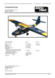
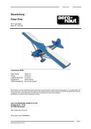
<strong>Fournier</strong> <strong>RF</strong>-<strong>4D</strong> building <strong>instructions</strong><br />
<strong>Fournier</strong> <strong>RF</strong>-<strong>4D</strong><br />
carefully and leave the epoxy to cure fully. When the epoxy is hard, withdraw the parts from the fuselage<br />
and - if necessary - trim the tailplane panels to match the root fairings on the fuselage.<br />
- The tailplane panels should not be installed permanently until the fuselage has been painted and the<br />
tailplane covered.<br />
You have already rubbed down the fuselage, but it must now be thoroughly de-greased before painting. An<br />
excellent method is to wash it using water with liquid detergent added. Wipe the entire surface with a wet<br />
cloth to remove grease, then rinse it more using clean water. Seal all the fuselage openings beforehand.<br />
Our <strong>RF</strong>-<strong>4D</strong> was sprayed with a base coat of Orapaint and sealed with Orapaint EKS clear lacquer (gloss<br />
finish). A highly convincing finish is obtained if you thin the clear lacquer very greatly (approx. 300%<br />
thinners).<br />
Installing the tailplane is now extremely simple: first roughen the joint surface of the integral root fairings<br />
using coarse abrasive paper. Apply sufficient thickened epoxy to the holes in the tailplane panels and<br />
distribute it evenly. Apply the same epoxy mixture to the root face of the tailplane panels. Apply a thin<br />
coating of epoxy to the joiner tubes (60) (already bonded-in) and slide them through the fuselage. Remove<br />
excess resin with a paper towel and clean the surfaces with petrol. Apply a few drops of epoxy to the inside<br />
joints between fuselage and joiner tubes, working through the openings in the tail post.<br />
When the resin has started to cure, press the parts together finally, clean the area once more and tape the<br />
tailplane panels to the fuselage.<br />
Now it’s the rudder’s turn: apply Vaseline to all parts of the hinge system, and only then fit the hinge shaft<br />
(45). Secure the shaft at the bottom.<br />
Thread the coil springs (56) into the tailskid actuator (48) and connect the other end to the lever on the<br />
tailskid. Apply a drop of thread-lock fluid to the threaded part of the tailskid retaining screw. Now place the<br />
coil springs under light tension, fit the screw in the actuator and tighten it. Apply a drop of oil for lubrication.<br />
After covering the elevator panels, glue the elevator horns (49) in the slots and attach the panels to the<br />
tailplane using the hinges (61). Grease the snake inners lightly and slide them into the outer sleeves from the<br />
front end. Connect the inners to the servo output arms. Connect clevises and threaded couplers to the<br />
elevator horns and establish the correct length of the snake inners (servos and elevators neutral / central).<br />
Cut off excess pushrod length and crimp the threaded couplers firmly onto the pushrods.<br />
The fuselage and cockpit can now be fitted out permanently. Important: before fitting the mudguard check<br />
the operation of the retract system carefully. It is important that the wheel doors work reliably every time.<br />
To install the retract unit we recommend a right-angled 3 mm A/F ball-end allen driver at least 125 mm long.<br />
This tool makes it relatively easy to reach the retract unit retaining screws through the opening in the motor<br />
bulkhead. Tighten the screws really firmly, and check again that they are really tight. Install the air cylinder<br />
and ensure that the control pin of the retract unit reaches the end-point of its guide. If not, adjust the clevis<br />
until it does. Tighten the actuating arm really thoroughly on its shaft.<br />
The air lines can now be connected: fit the hoses full-depth onto the nipples; this is easier if you first soften<br />
the hose slightly with heat from a match. Tighten the grubscrew in the pressure reducer until it is about 0.5 -<br />
1 mm below the surface of the body. The retraction time should be set to about two seconds. Pressurise the<br />
system - it is not necessary to set a pressure higher than 6 bar.<br />
Completing the wings starts with gluing the incidence tubes (67) in the root ribs: saw two pieces about 25<br />
mm long from the brass tube (67), and seal one end of each. Check that the tubes are an easy sliding fit in<br />
the holes in the fuselage root fairings. Fit the wing joiner tube through the fuselage and provisionally plug in<br />
the wings. Check that the trailing edge of the wings and the root fairings line up correctly. If necessary adjust<br />
the hole in the root rib. Apply thickened epoxy to the hole in the root rib, press the tubular incidence peg into<br />
it and wipe off excess resin. Allow the epoxy to harden slightly, then clean any resin residues from the tube<br />
using acetone and apply mould-release wax to it. Now push the wing against the fuselage as far as it will go<br />
and check that the end of the incidence tube does actually protrude inside the fuselage. Align the trailing<br />
edge of the wing and root fairing, then tape the parts together.<br />
Fig. 52 shows how the threaded sleeve for the wing retainer system (75) is installed. Use an M5 screw and,<br />
8