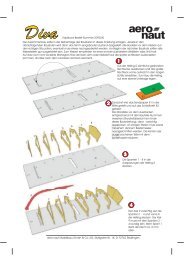
Building instructions Fournier RF-4D - Aero-naut
Building instructions Fournier RF-4D - Aero-naut
Building instructions Fournier RF-4D - Aero-naut

Create successful ePaper yourself
Turn your PDF publications into a flip-book with our unique Google optimized e-Paper software.
<strong>Fournier</strong> <strong>RF</strong>-<strong>4D</strong> building <strong>instructions</strong><br />
<strong>Fournier</strong> <strong>RF</strong>-<strong>4D</strong><br />
fueltank. With this installation the throttle servo has to be installed on the left-hand side of the fuselage. If you<br />
install a single-cylinder motor “side-winder” style, the servo will be mounted on the right-hand side.<br />
Back to the standard version; installation of a single-cylinder motor. Remove the machined inside section<br />
from the motor bulkhead; the two circular stiffening plates are parts (64). Fig. 5 shows the motor bulkhead<br />
with an extension to accommodate the fueltank (see above) to suit the Saito FA-100T. The plywood<br />
bulkhead (77) must be soaked thoroughly in laminating resin; see above re. part (3). When the epoxy has<br />
cured, fix the motor to the motor mount, position it as accurately as possible and drill the 5 mm Ø holes.<br />
Remove the motor mount and open up the holes to 6.5 mm Ø to accept the captive nuts supplied. Install the<br />
motor mount and motor and check that it is correctly positioned. Check also the distance to the front face of<br />
the propeller driver. The holes for the fuel system tubes and throttle linkage sleeve can now be drilled.<br />
To prevent oil and dirt entering the fuselage, the front face of the fuselage (= motor bulkhead) should be<br />
closed off using one of the plywood plates (54). Lay the motor bulkhead on part (54) and mark the holes on it<br />
from the bulkhead (77). Fit the M5 mounting screws through the holes. Now mark the outline of the bulkhead<br />
(77) on part (54) and saw it to size. Soak part (54) with resin to prevent it absorbing fuel.<br />
Figs. 8 and 9 show the retract unit and air cylinder installed.<br />
Cut out the mudguard (35) using tin-snips, leaving a strip about 7 mm wide on both sides. Cut a slot in the<br />
side of the moulding to clear the actuating shaft of the retract unit. Cut the two parts (36) (15 - 20 mm long)<br />
from hardwood strip and glue them to the side strips at the bottom; 2.2 Ø x 6.5 mm self-tapping screws are<br />
fitted into these parts to attach the mudguard (35) to the fuselage floor. Fig. 38 shows approximately where<br />
the screws should be fitted in order to coincide with the blocks. Fig. 29 shows the mudguard and fueltank,<br />
which in this case is positioned to suit the Saito FA-100T.<br />
The co-ordinates for the screws should now be marked as accurately as possible on the fuselage bottom<br />
using the mudguard as a template. Drill the holes 2.3 mm Ø. Place the mudguard in the fuselage (retract unit<br />
installed), drill the first 1.5 mm Ø hole and fit a screw to secure it. Carefully drill the remaining holes, taking<br />
care not to deform the moulding. The mudguard must be located centrally in the fuselage.<br />
Figs. 10, 11 and 12 shows the plastic cockpit components. Please take a close look at Fig. 12, which shows<br />
how the instrument panel has to be trimmed (the side areas are located in the fuselage recess).<br />
Fig. 13 shows the hinge and actuating system of the wheel well doors (10). Important: the doors are not<br />
symmetrical in the fore-and-aft direction. Align them carefully, and mark the front end. Bend the final 20 mm<br />
of the mild steel rods (11) at right-angles. Cut two pieces 78 mm long from the brass tube (12) and file a<br />
notch in the centre of each using a round file (lubricating point). Slip the tubes onto the steel rods (11). The<br />
second bend at the front end of parts (11) should be located about 145 mm from the rear bend. Important:<br />
this bend must be located about 8 - 10 mm forward of the front face of the mudguard. Don’t forget: these<br />
parts are “handed”, i.e. there are left-hand and right-hand hinge assemblies.<br />
Cut two pieces 15 mm long from part (13), fix them to the formed rods (11) with soft binding wire and solder<br />
the parts together as shown in the photos and on the plan.<br />
Detail “X” on the plan shows a cross-section through the hinge system for the wheel doors (10) on the<br />
bottom of the fuselage. Note that the inside of parts (10) must be flush with the fuselage floor where the<br />
brass bush (12) is located. The entire hinge / actuation system can now be glued to the wheel doors (10).<br />
Place a piece of 1.5 mm plywood between the tongues of parts (10) and lay the brass tube on the spacer;<br />
the shaft (part 11) should have about 0.5 mm clearance above the tongues, i.e. the wall thickness of parts<br />
(12). Position the parts as accurately as possible (the dimensions are stated in detail “X”), and glue them in<br />
place using plenty of thickened laminating resin.<br />
Fig. 14 shows all the servo mounts. Please note that the elevators are actuated using two micro-servos, as<br />
this arrangement allows the snake outers to be glued directly to the fuselage sides. Install a high-quality<br />
mini-servo for the rudder. The throttle servo should be mounted on the right-hand side of the fuselage for a<br />
single-cylinder motor. Figs. 15 - 18 also show how the servos are installed. Position the mounts in the<br />
fuselage, tack them in place with cyano, then reinforce the joints with laminating resin.<br />
The next step is to install the “snakes” in the fuselage; start by drilling the exit holes in the fuselage. File<br />
these out at a very flat angle to avoid kinking the snake inners (40). Fit an M2 nut and clevis (71) on each<br />
threaded coupler, slip them through the fuselage interior and out of the appropriate exit holes, then connect<br />
5