Building instructions Fournier RF-4D - Aero-naut
Building instructions Fournier RF-4D - Aero-naut
Building instructions Fournier RF-4D - Aero-naut

You also want an ePaper? Increase the reach of your titles
YUMPU automatically turns print PDFs into web optimized ePapers that Google loves.
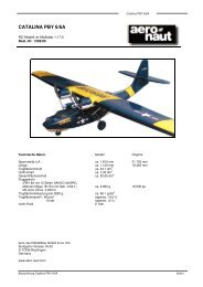
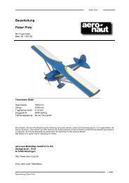
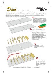
<strong>Fournier</strong> <strong>RF</strong>-<strong>4D</strong> building <strong>instructions</strong><br />
<strong>Fournier</strong> <strong>RF</strong>-<strong>4D</strong><br />
the clevises to the servo output arms. Slip the snake outers (39) onto parts (40) from the tail end. Align the<br />
projecting outer sleeves as shown on the plan (inside the fuselage they must run in smooth curves), press<br />
them against the fuselage and tack them in place using cyano. Secure each snake outer at three points with<br />
cyano, then apply thickened epoxy at each point, preferably with a patch of glass cloth. Withdraw the inner<br />
tubes and slice off the excess outer sleeves (39) using a sharp chisel. The remainder of the snakes is used<br />
for the throttle linkage.<br />
Next comes the air exit - Fig. 20 and the plan tell you all you need to know here.<br />
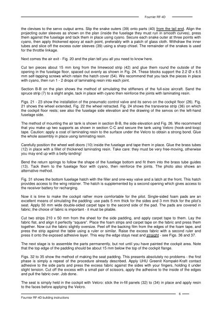
Cut ten pieces about 15 mm long from the limewood strip (42) and glue them round the outside of the<br />
opening in the fuselage floor, spaced out evenly as shown in Fig. 24. These blocks support the 2.2 Ø x 6.5<br />
mm self-tapping screws which retain the hatch cover (54). We recommend that you tack the pieces in place<br />
with cyano, then run 1 - 2 drops of laminating resin into each joint.<br />
Section B-B on the plan shows the method of simulating the stiffeners of the full-size aircraft. Sand the<br />
spruce strip (7) to a slight angle, tack in place with cyano then reinforce the joints with laminating resin.<br />
Figs. 21 - 23 show the installation of the pneumatic control valve and its servo on the cockpit floor (26). Fig.<br />
21 shows the wheel extended, Fig. 22 the wheel retracted. Fig. 24 shows the transverse strip (36) on which<br />
the cockpit floor rests; see also the fuselage side elevation and the drawing of the servos on the left-hand<br />
fuselage side.<br />
The method of mounting the air tank is shown in section B-B, the side elevation and Fig. 26. We recommend<br />
that you make up two supports as shown in section C-C and secure the tank using Velcro (hook-and-loop)<br />
tape. Caution: apply a coat of laminating resin to the surface under the Velcro to obtain a strong bond. Glue<br />
the whole assembly in place using laminating resin.<br />
Carefully position the wheel well doors (10) inside the fuselage and tape them in place. Glue the brass tubes<br />
(12) in place with a fillet of thickened laminating resin. Take care: they must be very free-moving, otherwise<br />
you may end up with a belly-landing!<br />
Bend the return springs to follow the shape of the fuselage bottom and fit them into the brass tube guides<br />
(13). Tack them to the fuselage floor with cyano, then reinforce the joints. The photo also shows an<br />
alternative method.<br />
Fig. 31 shows the bottom fuselage hatch with the filler and one-way valve and a latch at the front. This hatch<br />
provides access to the wing retainer. The hatch is supplemented by a second opening which gives access to<br />
the receiver battery for recharging.<br />
Now it is time to make the cockpit rather more comfortable for the pilot. Single-sided foam pads are an<br />
excellent means of simulating the padding: use pads 5 mm thick for the sides and 3 mm thick for the pilot’s<br />
seat. Apply 50 mm wide double-sided carpet tape to the second side of the pad. The pads are covered in<br />
fabric; the choice of fabric is important - it must be pliable.<br />
Cut two strips 210 x 50 mm from the sheet for the side padding, and apply carpet tape to them. Lay the<br />
fabric flat, and align it perfectly “square”. Place the foam strips and carpet tape on the fabric and press them<br />
together. Now cut the fabric slightly oversize. Peel off the backing film from the edges of the foam tape, and<br />
press the strip against the table using a ruler or similar. Raise the excess fabric with a second ruler and<br />
press it onto the exposed adhesive layer. This way the edge stays neat and straight - see Figs. 36 and 37.<br />
The next stage is to assemble the parts permanently, but not until you have painted the cockpit area. Note<br />
that the top edge of the padding should be about 15 mm below the top of the cockpit flange.<br />
Figs. 32 to 35 show the method of making the seat padding. This presents absolutely no problems - the first<br />
phase is simply a repeat of the procedure already described. Apply UHU Greenit Kompakt-Kraft contact<br />
adhesive to the side parts and press the excess fabric against the sides with your fingers, holding it under<br />
slight tension. Cut off the excess with a small pair of scissors, apply the adhesive to the inside of the edges<br />
and pull the fabric over. Job done.<br />
The seat is simply held in the cockpit with Velcro: stick the in-fill panels (32) to (34) in place and apply resin<br />
to the faces before applying the Velcro.<br />
6