Building instructions Fournier RF-4D - Aero-naut
Building instructions Fournier RF-4D - Aero-naut
Building instructions Fournier RF-4D - Aero-naut

Create successful ePaper yourself
Turn your PDF publications into a flip-book with our unique Google optimized e-Paper software.
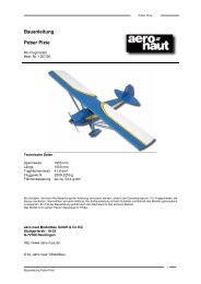
<strong>Fournier</strong> <strong>RF</strong>-<strong>4D</strong> building <strong>instructions</strong><br />
<strong>Fournier</strong> <strong>RF</strong>-<strong>4D</strong><br />
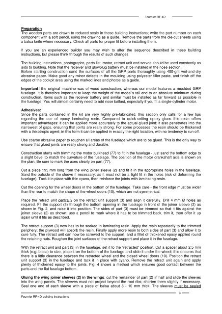
Preparation<br />
The wooden parts are drawn to reduced scale in these building <strong>instructions</strong>; write the part number on each<br />
component with a soft pencil, using the drawing as a guide. Remove the parts from the die-cut sheets using<br />
a balsa knife where necessary. Check all parts for proper fit before installing them.<br />
If you are an experienced builder you may wish to alter the sequence described in these building<br />
<strong>instructions</strong>, but please think through the results of such changes.<br />
The building <strong>instructions</strong>, photographs, parts list, motor, retract unit and servos should be used constantly as<br />
aids to building. Note that the receiver and glowplug battery must be installed in the nose section.<br />
Before starting construction sand the surfaces of all the GRP parts thoroughly using 400-grit wet-and-dry<br />
abrasive paper. Make good any minor defects in the moulding using polyester filler paste, and finish off the<br />
edges of the cockpit area using the marked lines and photos as a guide.<br />
Important! the original machine was of wood construction, whereas our model features a moulded GRP<br />
fuselage. It is therefore important to keep the weight of the model’s tail end to an absolute minimum during<br />
construction. Items such as the receiver battery and similar must be installed as far forward as possible in<br />
the fuselage. You will almost certainly need to add nose ballast, especially if you fit a single-cylinder motor.<br />
Adhesives:<br />
Since the parts contained in the kit are very highly pre-fabricated, this section only calls for a few tips<br />
regarding the use of epoxy laminating resin. Compared to quick-setting epoxy glues this resin offers<br />
important advantages: it can be applied more accurately to the actual glued joint; it also penetrates into the<br />
narrowest of gaps, ensuring that joints are really strong. For some processes the resin should be thickened<br />
with a thixotropic agent; in this form it can be applied in exactly the right location, with no tendency to run off.<br />
Use coarse abrasive paper to roughen all areas of the fuselage which are to be glued. This is the only way to<br />
ensure that glued joints are really strong and durable.<br />
Construction starts with trimming the motor bulkhead (77) to fit in the fuselage - just sand the bottom edge to<br />
a slight bevel to match the curvature of the fuselage. The position of the motor crankshaft axis is shown on<br />
the plan. Be sure to mark the axes clearly on part (77).<br />
Cut a piece 195 mm long from the wing joiner sleeve (2) and fit it in the appropriate holes in the fuselage.<br />
Sand the outside of the sleeve if necessary, as it must not be a tight fit in the holes (risk of deforming the<br />
fuselage). Tack it in place with thin cyano, then reinforce the joints with laminating resin.<br />
Cut the opening for the wheel doors in the bottom of the fuselage. Take care - the front edge must be wider<br />
than the rear to match the shape of the wheel doors (10), which are not symmetrical.<br />
Place the retract unit centrally on the retract unit support (3) and align it carefully. Drill 4 mm Ø holes as<br />
required. Fit the support (3) through the bottom opening in the fuselage in front of the joiner sleeve (2) as<br />
shown in Fig. 2, and raise it into position. The sides of part (3) must be trimmed so that it fits against the<br />
joiner sleeve (2) as shown; use a pencil to mark where it has to be trimmed back, trim it, then offer it up<br />
again until it fits as described.<br />
The retract support (3) now has to be soaked in laminating resin. Apply the resin repeatedly to the trimmed<br />
periphery; the plywood will absorb the resin. Finally apply more resin to both sides of part (3) and allow it to<br />
cure fully. The retract unit can now be screwed to the support, and a fillet of thickened epoxy applied round<br />
the retaining nuts. Roughen the joint surfaces of the retract support and place it in the fuselage.<br />
With the retract unit and part (3) in the fuselage, set it to the “retracted” position. Cut a spacer about 2.5 mm<br />
thick (e.g. balsa) to size, place it on the bottom of the fuselage and slide it under the wheel; this ensures that<br />
there is a little clearance between the retracted wheel and the closed wheel doors (10). Position the retract<br />
unit support (3) in the fuselage and tack it in place with cyano. Remove the retract unit again and apply<br />
plenty of thickened epoxy to the joints. Fig. 4 shows a method which ensures good contact between the<br />
parts and the flat fuselage bottom.<br />
Gluing the wing joiner sleeves (2) in the wings: cut the remainder of part (2) in half and slide the sleeves<br />
into the wing panels. The sleeves must not project beyond the root ribs; shorten them slightly if necessary.<br />
Seal one end of each sleeve with a piece of balsa about 8 - 10 mm thick. The sleeves must be sealed<br />
3