Building instructions Fournier RF-4D - Aero-naut
Building instructions Fournier RF-4D - Aero-naut
Building instructions Fournier RF-4D - Aero-naut

Create successful ePaper yourself
Turn your PDF publications into a flip-book with our unique Google optimized e-Paper software.
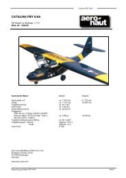
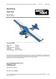
<strong>Fournier</strong> <strong>RF</strong>-<strong>4D</strong> building <strong>instructions</strong><br />
<strong>Fournier</strong> <strong>RF</strong>-<strong>4D</strong><br />
say, a captive nut to screw the sleeve in place. Fit the joiner tube in the wing and set the M5 screw parallel to<br />
it. Tap the sleeve into the root rib. The threaded rod of the retainer (75) must lie parallel to the wing joiner<br />
tube.<br />
Stick a sheet of new abrasive paper (approx. 180-grit) to a flat sanding block, and use this to sand the wing<br />
surfaces to a fine finish. Three templates are supplied (S1 - S3) for shaping the wing leading edge to the<br />
exact profile; sand the root to match the fuselage root fairing. The trailing edge should also be carefully<br />
sanded down to an even thickness of about 0.5 - 1 mm. Trim the wingtips (63) roughly to follow the wing<br />
section, glue them in place, then finish them off using a balsa plane and the sanding block.<br />
Remove foam from the servo wells to provide proper clearance, keeping the servo cable openings free. For<br />
the aileron linkage we recommend mini-sized wing-mounting servos, whereas good micro-servos are<br />
sufficient for the airbrakes. Figs. 55 and 56 show how the servos are mounted on the plywood plates (68).<br />
Glue the plates in the wings using thickened epoxy.<br />
Dismantle the airbrakes (69) as shown in Fig. 53 (just push the levers out of the bottom pivots using a<br />
screwdriver) and place the box in the slot in each wing. The top edge of the box should be recessed about<br />
1.5 mm under the top surface; adjust the brake slot if necessary until this is the case. Roughen the<br />
aluminium box with coarse abrasive paper, de-grease the surfaces and glue it in the slot using thickened<br />
epoxy. Cut in-fill pieces (73) from the balsa strip to cover the top flanges of the box. When the glue has set<br />
hard, trim the edges of the strips to provide clearance for the brake, and install the airbrake. Cut the airbrake<br />
capstrip from part (73) leaving about 1 mm clearance all round the edges. Tack the capstrip to the airbrake<br />
blade using cyano, then carefully sand all three strips flush with the wing surface. Extend the airbrake,<br />
remove it and reinforce the joints with epoxy.<br />
Important: each airbrake servo should be connected to its own receiver channel, i.e. please don’t use Yleads.<br />
This way it is much easier to synchronise the brakes. The servos are already in place (but not<br />
permanently); run them to the “brakes retracted” end-point.<br />
The servo linkage consists of the threaded rod (70) and clevis (72). The rods (70) must first be cut to correct<br />
length. Connect the clevis (72) to the airbrake, slip it into the box and press it onto the pivots. The pushrod<br />
(70) projects into the servo well. The pushrod (70) must be pulled forward (towards the wing root) to its endpoint<br />
to give access to the brake mechanism. Using a soft pencil mark the position of the hole in the servo<br />
output arm on the pushrod (70), then remove the brake again. Bend the pushrod (70) at right-angles as<br />
accurately as you can at the marked point, cut off the excess rod length and file the end smooth. Re-install<br />
the brake. The position of the bend will probably not be exactly right, so screw the pushrod (70) in or out of<br />
the clevis (72) to correct the length. Check the operation of the airbrake system from the transmitter. Remove<br />
the airbrake again and cut two washers about 5 mm Ø from the scrap vacuum-moulding material, with a 1.6<br />
mm Ø hole. Slip these onto the bent pushrod (7) and fix them to the rod with Loctite when the airbrakes are<br />
finally installed (wing top surface covered).<br />
Remove the stiffening plates (64) from the motor bulkhead, drill 2.5 mm Ø holes in them as shown and push<br />
the outboard wheel supports (76) into them. Cut channels for the 4 mm Ø hardwood dowels as shown on the<br />
plan and Fig. 62, and fit the outboard wheels together with the aluminium spreader plates in the plates (64).<br />
Apply a drop of oil to the end of the three M2.5 mm pan-head screws. Fit these assemblies in the wing, and<br />
drill 4 mm Ø holes as shown on the plan and section F-F to accept the hardwood dowels (65). Remove all<br />
the parts and clear away the scrap foam from the recess. The parts are glued in place using thickened<br />
epoxy: apply plenty of resin in the recess, then press the complete assembly into place. Mix up some fresh<br />
low-viscosity resin and gradually fill the side holes until you are confident of a really strong glued joint. The<br />
dowels (65) ensure that the landing loads are spread adequately in the wing.<br />
We recommend using twisted 0.25 mm² cable for the servo extension leads. Solder the aileron servo directly<br />
to the extension lead, and attach the airbrake servo cable to the aileron lead using a heat-shrink sleeve or<br />
similar (the airbrake servo cannot be soldered to the extension lead until the loom has been fitted through<br />
the wing). The cable can easily be drawn through the wing using a length of 0.8 mm Ø steel rod: form a loop<br />
in one end, fit this through the root rib and tie the extension cable to the loop using soft binding wire or<br />
similar; the lead can now be pulled through the wing. Solder the brake servo to the extension lead - see Fig.<br />
57 - and a 6-pin plug. Glue the matching socket in the fuselage.<br />
Sand the top edge of the aileron leading edge to a chamfer as shown in section G-G and cut slight recesses<br />
to accommodate the central knuckle of the hinges - see Fig. 59. Cut slots for the aileron horns; these must<br />
9