Passage to a Ringed World - NASA's History Office
Passage to a Ringed World - NASA's History Office
Passage to a Ringed World - NASA's History Office

You also want an ePaper? Increase the reach of your titles
YUMPU automatically turns print PDFs into web optimized ePapers that Google loves.
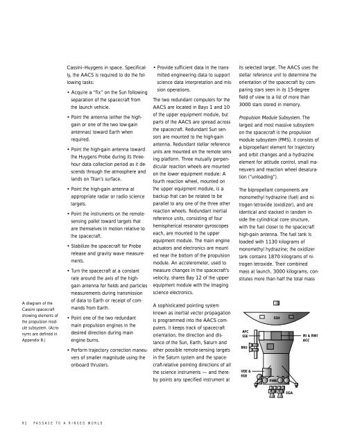
A diagram of the<br />
Cassini spacecraft<br />
showing elements of<br />
the propulsion module<br />
subsystem. (Acronyms<br />
are defined in<br />
Appendix B.)<br />
92 PASSAGE TO A RINGED WORLD<br />
Cassini–Huygens in space. Specifically,<br />
the AACS is required <strong>to</strong> do the following<br />
tasks:<br />
• Acquire a “fix” on the Sun following<br />
separation of the spacecraft from<br />
the launch vehicle.<br />
• Point the antenna (either the highgain<br />
or one of the two low-gain<br />
antennas) <strong>to</strong>ward Earth when<br />
required.<br />
• Point the high-gain antenna <strong>to</strong>ward<br />
the Huygens Probe during its threehour<br />
data collection period as it descends<br />
through the atmosphere and<br />
lands on Titan’s surface.<br />
• Point the high-gain antenna at<br />
appropriate radar or radio science<br />
targets.<br />
• Point the instruments on the remotesensing<br />
pallet <strong>to</strong>ward targets that<br />
are themselves in motion relative <strong>to</strong><br />
the spacecraft.<br />
• Stabilize the spacecraft for Probe<br />
release and gravity wave measurements.<br />
• Turn the spacecraft at a constant<br />
rate around the axis of the highgain<br />
antenna for fields and particles<br />
measurements during transmission<br />
of data <strong>to</strong> Earth or receipt of commands<br />
from Earth.<br />
• Point one of the two redundant<br />
main propulsion engines in the<br />
desired direction during main<br />
engine burns.<br />
• Perform trajec<strong>to</strong>ry correction maneuvers<br />
of smaller magnitude using the<br />
onboard thrusters.<br />
• Provide sufficient data in the transmitted<br />
engineering data <strong>to</strong> support<br />
science data interpretation and mission<br />
operations.<br />
The two redundant computers for the<br />
AACS are located in Bays 1 and 10<br />
of the upper equipment module, but<br />
parts of the AACS are spread across<br />
the spacecraft. Redundant Sun sensors<br />
are mounted <strong>to</strong> the high-gain<br />
antenna. Redundant stellar reference<br />
units are mounted on the remote sensing<br />
platform. Three mutually perpendicular<br />
reaction wheels are mounted<br />
on the lower equipment module: A<br />
fourth reaction wheel, mounted on<br />
the upper equipment module, is a<br />
backup that can be rotated <strong>to</strong> be<br />
parallel <strong>to</strong> any one of the three other<br />
reaction wheels. Redundant inertial<br />
reference units, consisting of four<br />
hemispherical resona<strong>to</strong>r gyroscopes<br />
each, are mounted <strong>to</strong> the upper<br />
equipment module. The main engine<br />
actua<strong>to</strong>rs and electronics are mounted<br />
near the bot<strong>to</strong>m of the propulsion<br />
module. An accelerometer, used <strong>to</strong><br />
measure changes in the spacecraft’s<br />
velocity, shares Bay 12 of the upper<br />
equipment module with the imaging<br />
science electronics.<br />
A sophisticated pointing system<br />
known as inertial vec<strong>to</strong>r propagation<br />
is programmed in<strong>to</strong> the AACS computers.<br />
It keeps track of spacecraft<br />
orientation, the direction and distance<br />
of the Sun, Earth, Saturn and<br />
other possible remote-sensing targets<br />
in the Saturn system and the spacecraft-relative<br />
pointing directions of all<br />
the science instruments — and thereby<br />
points any specified instrument at<br />
its selected target. The AACS uses the<br />
stellar reference unit <strong>to</strong> determine the<br />
orientation of the spacecraft by comparing<br />
stars seen in its 15-degree<br />
field of view <strong>to</strong> a list of more than<br />
3000 stars s<strong>to</strong>red in memory.<br />
Propulsion Module Subsystem. The<br />
largest and most massive subsystem<br />
on the spacecraft is the propulsion<br />
module subsystem (PMS). It consists of<br />
a bipropellant element for trajec<strong>to</strong>ry<br />
and orbit changes and a hydrazine<br />
element for attitude control, small maneuvers<br />
and reaction wheel desaturation<br />
(“unloading”).<br />
The bipropellant components are<br />
monomethyl hydrazine (fuel) and nitrogen<br />
tetroxide (oxidizer), and are<br />
identical and stacked in tandem inside<br />
the cylindrical core structure,<br />
with the fuel closer <strong>to</strong> the spacecraft<br />
high-gain antenna. The fuel tank is<br />
loaded with 1130 kilograms of<br />
monomethyl hydrazine; the oxidizer<br />
tank contains 1870 kilograms of nitrogen<br />
tetroxide. Their combined<br />
mass at launch, 3000 kilograms, constitutes<br />
more than half the <strong>to</strong>tal mass<br />
AFC<br />
SSE<br />
BRU<br />
VDE &<br />
EGE<br />
SSH<br />
RWA<br />
EGA<br />
IRI & RWI<br />
ACC