


Create successful ePaper yourself
Turn your PDF publications into a flip-book with our unique Google optimized e-Paper software.
Mini Tutorial<br />
MT-203<br />
One Technology Way • P.O. Box 9106 • Norwood, MA 02062-9106, U.S.A. • Tel: 781.329.4700 • Fax: 781.461.3113 • www.analog.com<br />
<strong>Bainter</strong> <strong>Notch</strong> <strong>Filters</strong><br />
by Hank Zumbahlen,<br />
<strong>Analog</strong> <strong>Devices</strong>, Inc.<br />
IN THIS MINI TUTORIAL<br />
A simple notch filter is the <strong>Bainter</strong> operational amplifier<br />
(op amp) notch filter, one of multiple discrete circuits<br />
described in a series of mini tutorials.<br />
INTRODUCTION TO BAINTER NOTCH FILTERS<br />
A simple notch filter is the <strong>Bainter</strong> circuit (see the Reference<br />
section). It is composed of simple circuit blocks with two<br />
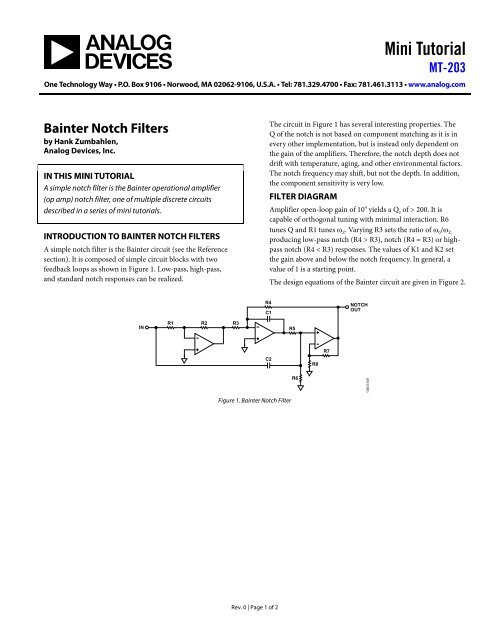
feedback loops as shown in Figure 1. Low-pass, high-pass,<br />
and standard notch responses can be realized.<br />
IN<br />
R1 R2 R3<br />
Figure 1. <strong>Bainter</strong> <strong>Notch</strong> Filter<br />
Rev. 0 | Page 1 of 2<br />
The circuit in Figure 1 has several interesting properties. The<br />
Q of the notch is not based on component matching as it is in<br />
every other implementation, but is instead only dependent on<br />
the gain of the amplifiers. Therefore, the notch depth does not<br />
drift with temperature, aging, and other environmental factors.<br />
The notch frequency may shift, but not the depth. In addition,<br />
the component sensitivity is very low.<br />
FILTER DIAGRAM<br />
Amplifier open-loop gain of 10 4 yields a Qz of > 200. It is<br />
capable of orthogonal tuning with minimal interaction. R6<br />
tunes Q and R1 tunes ωZ. Varying R3 sets the ratio of ω0/ωZ, producing low-pass notch (R4 > R3), notch (R4 = R3) or highpass<br />
notch (R4 < R3) responses. The values of K1 and K2 set<br />
the gain above and below the notch frequency. In general, a<br />
value of 1 is a starting point.<br />
The design equations of the <strong>Bainter</strong> circuit are given in Figure 2.<br />
R4<br />
C1<br />
C2<br />
R5<br />
R6<br />
R8<br />
R7<br />
NOTCH<br />
OUT<br />
10403-001
MT-203 Mini Tutorial<br />
DESIGN EQUATIONS<br />
REFERENCES<br />
Figure 2. <strong>Bainter</strong> <strong>Notch</strong> Filter Design Equations<br />
<strong>Bainter</strong>, J. R. "Active Filter Has Stable <strong>Notch</strong> and Response Can Be Regulated," Electronics, Oct. 2, 1975, pages 115 to 117.<br />
Zumbahlen, Hank. Linear Circuit Design Handbook. Elsevier. 2008. ISBN: 978-7506-8703-4.<br />
REVISION HISTORY<br />
4/12—Revision 0: Initial Version<br />
IN<br />
R1 R2 R3<br />
H (S2 + ωZ2) S2 ω0 + S + ω 2<br />
Q 0<br />
CHOOSE C1, R1, R7, K1, K2<br />
C2 = C1 = C<br />
k = 2 π FO C<br />
R2 = K1 × R1<br />
2<br />
ωZ Z =<br />
ω0 K1<br />
R3 =<br />
2 Z Q k<br />
©2012 <strong>Analog</strong> <strong>Devices</strong>, Inc. All rights reserved. Trademarks and<br />
registered trademarks are the property of their respective owners.<br />
MT10401-0-4/12(0)<br />
BAINTER NOTCH<br />
R4<br />
C1<br />
C2<br />
Rev. 0 | Page 2 of 2<br />
R5<br />
R8<br />
R7<br />
(R5 + R6)<br />
S<br />
R5 R6 C2<br />
2 S<br />
VOUT =<br />
VIN K2<br />
+<br />
S +<br />
R4 R5 C1 C2<br />
2 K1<br />
K2 × +<br />
R3 R5 C1 C2<br />
K2<br />
R4 =<br />
2 Q k<br />
2 Q<br />
R5 = R6 =<br />
k<br />
R8 = (K2 – 1) R7<br />
R6<br />
OUT<br />
10401-002


