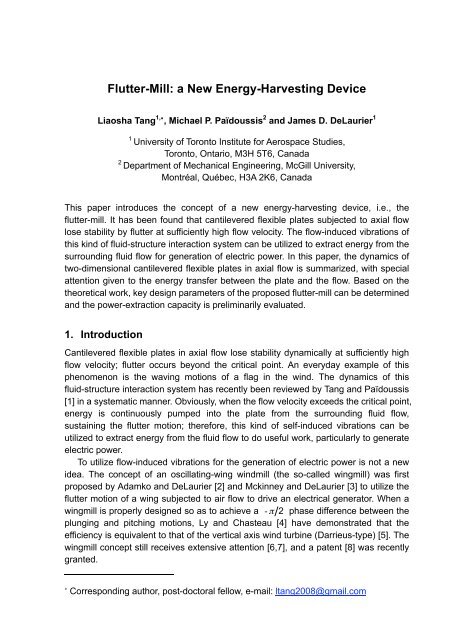
Flutter-Mill: a New Energy-Harvesting Device
Flutter-Mill: a New Energy-Harvesting Device
Flutter-Mill: a New Energy-Harvesting Device

You also want an ePaper? Increase the reach of your titles
YUMPU automatically turns print PDFs into web optimized ePapers that Google loves.
<strong>Flutter</strong>-<strong>Mill</strong>: a <strong>New</strong> <strong>Energy</strong>-<strong>Harvesting</strong> <strong>Device</strong><br />
Liaosha Tang 1,∗ , Michael P. Païdoussis 2 and James D. DeLaurier 1<br />
1 University of Toronto Institute for Aerospace Studies,<br />
Toronto, Ontario, M3H 5T6, Canada<br />
2 Department of Mechanical Engineering, McGill University,<br />
Montréal, Québec, H3A 2K6, Canada<br />
This paper introduces the concept of a new energy-harvesting device, i.e., the<br />
flutter-mill. It has been found that cantilevered flexible plates subjected to axial flow<br />
lose stability by flutter at sufficiently high flow velocity. The flow-induced vibrations of<br />
this kind of fluid-structure interaction system can be utilized to extract energy from the<br />
surrounding fluid flow for generation of electric power. In this paper, the dynamics of<br />
two-dimensional cantilevered flexible plates in axial flow is summarized, with special<br />
attention given to the energy transfer between the plate and the flow. Based on the<br />
theoretical work, key design parameters of the proposed flutter-mill can be determined<br />
and the power-extraction capacity is preliminarily evaluated.<br />
1. Introduction<br />
Cantilevered flexible plates in axial flow lose stability dynamically at sufficiently high<br />
flow velocity; flutter occurs beyond the critical point. An everyday example of this<br />
phenomenon is the waving motions of a flag in the wind. The dynamics of this<br />
fluid-structure interaction system has recently been reviewed by Tang and Païdoussis<br />
[1] in a systematic manner. Obviously, when the flow velocity exceeds the critical point,<br />
energy is continuously pumped into the plate from the surrounding fluid flow,<br />
sustaining the flutter motion; therefore, this kind of self-induced vibrations can be<br />
utilized to extract energy from the fluid flow to do useful work, particularly to generate<br />
electric power.<br />
To utilize flow-induced vibrations for the generation of electric power is not a new<br />
idea. The concept of an oscillating-wing windmill (the so-called wingmill) was first<br />
proposed by Adamko and DeLaurier [2] and Mckinney and DeLaurier [3] to utilize the<br />
flutter motion of a wing subjected to air flow to drive an electrical generator. When a<br />
wingmill is properly designed so as to achieve a phase difference between the<br />
plunging and pitching motions, Ly and Chasteau [4] have demonstrated that the<br />
efficiency is equivalent to that of the vertical axis wind turbine (Darrieus-type) [5]. The<br />
wingmill concept still receives extensive attention [6,7], and a patent [8] was recently<br />
granted.<br />
∗ Corresponding author, post-doctoral fellow, e-mail: ltang2008@gmail.com
This paper<br />
introduces the<br />
conceptual<br />
design of a new<br />
energy-<br />
harvesting<br />
device, named<br />
the flutter-mill.<br />
As shown in Fig.<br />
1, a cantilevered<br />
flexible plate<br />
with embedded<br />
conductors is<br />
placed in an<br />
axial (air) flow<br />
and between a<br />
pair of magnetic<br />
panels. When<br />
flutter takes<br />
place, the<br />
motion of each conductor in the magnetic field generates an electric potential<br />
difference between its upstream and downstream ends. In this paper, the dynamics of<br />
two-dimensional cantilevered flexible plates in axial flow is first summarized; special<br />
attention is given to the energy transfer between the plate and the surrounding fluid<br />
flow. In the light of the dynamics and the accompanying energy transfer of the system,<br />
the key design parameters of the flutter-mill are determined. Moreover, the<br />
power-extraction performance of flutter‐mills, with two typical sets of key design<br />
parameters, is preliminarily evaluated and compared to a real Horizontal Axial Wind<br />
Turbine (HAWT) studied by Burton et al. [9].<br />
2. The fluid-elastic model<br />
A schematic diagram of<br />
a cantilevered flexible<br />
plate in axial flow is<br />
shown in Fig. 2. The<br />
geometrical<br />
characteristics of the<br />
rectangular<br />
Fig. 1: The conceptual design of a flutter-mill: (a) the layout of the<br />
system, and (b) the wiring scheme.<br />
Fig. 2: A cantilevered flexible in axial flow.<br />
homogeneous plate are the length of the flexible section L, width B and thickness h;<br />
and for a thin two-dimensional plate. Normally, there is a rigid<br />
segment of length L0 as part of the clamping arrangement at the upstream end. The
other physical parameters of the system are: the plate material density and<br />
bending stiffness , where E and are, respectively, Young's<br />
modulus and the Poisson ratio of the plate material, the fluid density , and the<br />
undisturbed flow velocity U. As shown in Fig. 2, W and V are, respectively, the<br />
transverse and longitudinal displacements of the plate. and are the<br />
aerodynamic loads acting on the plate in the transverse and longitudinal direction. S is<br />
the distance of a material point on the plate from the origin, measured along the plate<br />
centreline in a coordinate system embedded in the plate. Moreover, material damping<br />
of the Kelvin-Voigt type is considered for the plate, with the loss coefficient denoted by<br />
a.<br />
The equations of motion of the plate can be written in nondimensional form as (see<br />
Ref. [1])<br />
where the overdot and the prime represent and , respectively. The<br />
nondimensional tension in the plate is given by<br />
The nondimensional variables used in Eqs. (1)−(3) are defined by<br />
where and are, respectively, nondimensional and dimensional vibration<br />
frequencies. Moreover, the mass ratio and the reduced flow velocity are<br />
defined by<br />
In Eqs. (1) and (3), and are calculated using the unsteady lumped vortex<br />
model (see Ref. [1]). To do this, the flexible plate is evenly divided into panels,<br />
each of length (note that the plate is assumed to be inextensible). On each<br />
individual panel, say the ith panel, the pressure difference across the plate can<br />
be computed and then decomposed into the lift and the drag . That is<br />
(1)<br />
(2)<br />
(3)<br />
(4)<br />
(5)<br />
(6)
where is the incidence angle of the ith panel. In the second equation above, an<br />
additional drag coefficient is considered to be uniformly distributed over the<br />
whole length of the plate, to account for the viscous drag effects.<br />
3. The dynamics and energy transfer<br />
The dynamics of<br />
two-dimensional<br />
cantilevered<br />
flexible plates in<br />
axial flow has<br />
recently been<br />
investigated by<br />
Tang and<br />
Païdoussis [1] in a<br />
multiple-<br />
parameter space.<br />
When the reduced<br />
flow velocity<br />
is low, the plate<br />
remains in the<br />
stretched-straight<br />
state. When<br />
exceeds the<br />
Fig. 3: (a) The power of the work and (b) the accumulated work done<br />
by the fluid load fL, and the calculation of time-averaged power .<br />
The parameters of the system are: , , ,<br />
and .<br />
critical point , flutter takes place; as is increased further, the flutter amplitude<br />
grows but the flutter mode remains qualitatively the same. The flutter mode of the<br />
system is principally determined by the mass ratio : when is small, the plate<br />
vibrates in a second-beam-mode shape (note that the plate never flutters in a pure<br />
first-beam-mode shape). With increasing , higher-order modes participate in the<br />
dynamics and become increasingly significant. It should be emphasized that points at<br />
different locations along the length of the plate do not oscillate in phase; as some<br />
parts of the plate move upwards, others may move downwards.<br />
It follows from Eqs. (1) and (6) that the nondimensional power of the work<br />
done by the transverse fluid load and the nondimensional accumulated work<br />
on the ith panel, in the sense of per unit length along the spanwise dimension of<br />
the plate, can be calculated from<br />
Therefore, over the whole length of the plate, the nondimensional total power and<br />
the nondimensional accumulated total work , respectively, can be calculated by<br />
(7)<br />
(8)
Note that is the time integral of . When the plate flutters, also oscillates<br />
about zero, as shown in Fig. 3. That is, in a vibration cycle, fL does both positive work<br />
(energy transferred from the fluid flow to the plate) and negative work. Since<br />
oscillates, the plot of versus time is not smooth (see Fig. 3(b)). The oscillating<br />
may be evaluated in terms of the time-averaged power . In this paper, as<br />
illustrated in the inset of Fig. 3(b), one may conveniently use the slope of the<br />
versus time, in terms of the line connecting the local maxima, to calculate .<br />
Moreover, according to the nondimensionalization scheme defined in Eq. (4), the<br />
dimensional time-averaged power can be calculated by<br />
Since points at<br />
different locations<br />
along the length of<br />
the plate do not<br />
oscillate in phase,<br />
and the flutter mode<br />
depends on , it is<br />
important to examine<br />
the energy transfer all<br />
along the plate for<br />
various systems with<br />
different values of .<br />
As shown in Fig. 4<br />
for a specific system<br />
with ,<br />
, the<br />
energy transfer at<br />
various locations is<br />
not the same: energy<br />
is pumped from the<br />
fluid flow into the<br />
plate (positive slope<br />
of the versus<br />
time plot) at points<br />
through<br />
; while it is<br />
transferred from the<br />
plate to the fluid flow<br />
at other locations (i.e.,<br />
points<br />
through ). Note<br />
Fig. 4: The energy exchange along the length of the plate: (a) the<br />
flutter modes, (b) the work done by fL at various locations, (c) a<br />
regional enlargement of (b), and (d) the total work done by fL. The<br />
parameters used are: , , ,<br />
and . panels are used in the numerical simulation.<br />
The energy transfer at 40 locations (every 5 panels) is recorded<br />
and the results at 10 locations (every 20 panels) are presented.<br />
(9)
that in this case the total work done by fL is positive, as shown in Fig. 4(d).<br />
Fig. 5: When flutter takes place, the positive/negative (P/N) work done by the fluid load fL at<br />
various locations along the length of the plate: (a) , , (b) ,<br />
, (c) , , (d) , , (e) , , and (f)<br />
, . The other parameters of the system are: , and<br />
. Note that, is used for the cases and ; while, for the other<br />
cases , and , is used. The energy transfers at 40 locations<br />
(every 5 panels in the case of and every 10 panels when ) are recorded.<br />
The distribution of positive/negative is also examined for various systems<br />
with different values of , as shown in Fig. 5. It should be mentioned that different<br />
values of are used for individual cases of for the purpose of obtaining flutter<br />
motions (in particular, is so chosen about 10% above the corresponding critical<br />
point ). It can be seen in Fig. 5 that the distribution of positive/negative<br />
depends on . When is large, say or 5, higher modes become important<br />
in the dynamics [1], and the distribution of positive/negative has a complicated<br />
pattern. It should be mentioned that the distribution of the positive/negative also<br />
depends on the value of , as one may see in Figs. 5(b) and (c); however, it has
een shown that this variation normally occurs at locations close to the fixed and free<br />
ends of the plate, where the level of energy transfer is much lower than elsewhere<br />
(refer to Fig. 4(b)).<br />
4. The design of the flutter-mill<br />
4.1. Determination of key design parameters<br />
It has been shown that, at different sections of the plate, the energy transfer may<br />
be from the fluid flow to the plate or<br />
vice versa. Therefore, the conductors<br />
embedded in the flexible plate should<br />
be correspondingly arranged in<br />
several sections, or say phases. Too<br />
many phases of conductor<br />
arrangement lead to difficulties in the<br />
design of the wiring scheme and the<br />
rectifier. To this end, in the light of the<br />
vibration modes of the system with<br />
various values of (see Fig. 12 of<br />
Ref. [1], also Figs. 4<br />
and 5 in the present<br />
paper), a system<br />
with mass ratio<br />
should be<br />
considered, for<br />
which the plate<br />
vibrates in the<br />
second beam mode.<br />
Hence, only two<br />
phases of conductor<br />
arrangement are<br />
necessary. The<br />
present paper<br />
primarily considers<br />
two cases:<br />
and 0.2.<br />
In the conceptual<br />
design, dimensional<br />
parameters allow<br />
one to evaluate the<br />
performance of the<br />
device in a more<br />
Table 1: Dimensional parameters of the<br />
flutter-mills with and 0.2.<br />
Plate 1 Plate 2 Unit<br />
1.226 1.226 kg/m 3<br />
2840 2840 kg/m 3<br />
h 0.5 0.5 mm<br />
L 0.58 0.232 m<br />
B 0.2 0.2 m<br />
0.5 0.2<br />
Fig. 6: The dynamics of the system with and the<br />
time-averaged power of the fluid load fL: (a) the bifurcation<br />
diagram, (b) the flutter frequency, and (c) the time-averaged power<br />
. The other parameters of the system are: ,<br />
and .
direct manner;<br />
accordingly plates<br />
made of aluminium in<br />
axial air flow [10] are<br />
considered. The reason<br />
for considering a<br />
metallic plate is that, in<br />
the prototype, (metal)<br />
conductors are<br />
supposed to be<br />
embedded in the plate,<br />
otherwise made of a<br />
very flexible material;<br />
the properties of this<br />
composite plate would<br />
thus be largely<br />
determined by those of<br />
the conductors. The<br />
parameters of the two<br />
systems with<br />
and 0.2 are,<br />
respectively, listed in<br />
Table 1.<br />
Fig. 7: The dynamics of the system with and the<br />
time-averaged power of the fluid load fL: (a) the bifurcation<br />
diagram, (b) the flutter frequency, and (c) the time-averaged<br />
power . The other parameters of the system are: ,<br />
and .<br />
Some explanation is necessary for the data in Table 1. First, since nondimensional<br />
parameters are used in all numerical simulations, the physical parameters of the<br />
systems listed in Table 1 are actually obtained using a reverse approach: for an<br />
aluminium plate in axial air flow, the physical parameters , , E, and a are<br />
fixed; the thickness of the plate is determined as mm and then the length of<br />
the plate L can be calculated for the case or 0.2. Second, the<br />
nondimensional parameters , and are uniformly used in<br />
all numerical simulations for simplicity; the influence of these parameters on the<br />
dynamics of the system has already been discussed in Ref. [1]. Third, m is<br />
considered in the conceptual design in order to avoid possible difficulties in attaining<br />
sufficient strength of the magnetic field between the two magnetic panels. Note that<br />
the value of B is not used in the investigation of the dynamics (nor in the energy<br />
transfer in terms of per unit length along the spanwise dimension) of a<br />
two-dimensional plate in axial flow.<br />
As shown in Figs. 6 and 7, preliminary calculations of the power extraction from the<br />
fluid flow demonstrate that the proposed flutter-mill is very promising for generation of<br />
electric power. In particular, consider a design with Plate 1 ( ), the device is<br />
compact, with overall dimensions 0.58 m (length) x 0.2 m (width) x 0.58 m (height),<br />
where the height is considered as twice the allowed maximum flutter amplitude (i.e.,<br />
half of the length of the flexible plate). Such a system can be expected to extract 10
Watt power (at m/s or 43.2 km/h) from the wind; and, if only 10% of the<br />
extracted wind energy is ultimately converted to electric power, an output of 1 Watt is<br />
guaranteed. Higher power output can be expected from the system with Plate 2<br />
( ), which has even smaller overall dimensions (0.232 m x 0.2 m x 0.232 m)<br />
but works at higher flow velocities. The power extraction is as high as 1 kW/m at<br />
m/s or 144 km/h approximately.<br />
4.2. The performance of power extraction from a flutter-mill<br />
The performance of the flutter-mill is compared to a real HAWT (Horizontal-Axis<br />
Wind Turbine), specifically the Three-Blade Stall Regulated Turbine studied by Burton<br />
et al. [9], in terms of<br />
measured electric<br />
power output, as shown<br />
in Fig. 8. The HAWT<br />
has a disk area<br />
m 2 and the<br />
data for electric power<br />
output is collected at a<br />
rotational speed of 44<br />
rpm. In order to make a<br />
comparison, one<br />
supposes that the<br />
flutter-mill has the<br />
same wind receiving<br />
area A as the HAWT<br />
and accordingly<br />
calculate the effective<br />
Fig. 8: The performance of the flutter-mill as compared to a real<br />
HAWT, i.e., the Three-blade Stall Regulated Turbine studied by<br />
Burton et al. [9].<br />
width Beff of the plate using the formula , where<br />
is the vibration amplitude at the trailing edge of the plate. Note that the effective width<br />
Beff can be attained by considering an array of flutter-mills, each one having a<br />
designed width of m. Moreover, in the calculation of electric power output, it<br />
is assumed that only 10% of the energy captured by the plate is ultimately converted<br />
to electric power; the other 90% is consumed by the plate for sustaining the flutter<br />
motion (under the action of the induced electromagnetic forces). It can be seen in Fig.<br />
8 that when , the flutter-mill works at the lower part of the wind speed range of<br />
the HAWT; however, the electric power output of the flutter-mill is not as high as that of<br />
the HAWT (about 10%). When it is designed with , the flutter-mill works at<br />
high wind speed beyond the normal working condition of the HAWT, but a very high<br />
electric power output can be expected. Therefore, it is possible to design a flutter-mill<br />
with a mass ratio between and 0.2 to achieve an output capacity comparable<br />
to the real HAWT, and to operate in the same range of wind speed as the HAWT.
5. Concluding remarks<br />
A new energy-harvesting concept of utilizing the flutter motions of cantilevered<br />
flexible plates in axial flow to generate electric power, namely the flutter-mill, is<br />
proposed in this paper. The dynamics of the system and the energy transfer between<br />
the plate and the surrounding fluid flow have been studied. Based on the theoretical<br />
work, the key design parameters are determined. Without a comprehensive<br />
optimization process at the present stage of conceptual design, the performance of<br />
the flutter-mill is preliminarily evaluated and compared to a real conventional wind<br />
turbine. It has been shown that the proposed design of flutter‐mill, with the<br />
distinguishing advantages of simple structure and compact size, is very promising for<br />
generation of electrical power.<br />
Acknowledge<br />
The leading author gratefully acknowledges the support by a Natural Sciences and<br />
Engineering Research Council of Canada (NSERC) post-doctoral fellowship.<br />
Reference<br />
[1] L. Tang, M. P. Païdoussis, “On the instability and the post-critical behavior of<br />
two-dimensional cantilevered flexible plates in axial flow,” Journal of Sound and<br />
Vibration 305 (2007) 97−115.<br />
[2] D. A. Adamko, J. D. DeLaurier, “An experimental study of an oscillating-wing<br />
windmill,” Proceedings of the Second Canadian Workshop on Wind Engineering<br />
(1978) 64−66.<br />
[3] W. McKinney, J. D. DeLaurier, “The wingmill: An oscillating-wing windmill,”<br />
Journal of <strong>Energy</strong> 5 (1981) 109−115.<br />
[4] K. H. Ly, V. A. L. Chasteau, “Experiments on an oscillating-wing aerofoil and<br />
application to wing-energy converters,” Journal of <strong>Energy</strong> 5 (1981) 116−121.<br />
[5] J. F. Manwell, J. G. McGowan, A. L. Rogers, “Wind <strong>Energy</strong> Explained: Theory,<br />
Design and Application,” John Wiley & Sons, Inc., <strong>New</strong> York, 2002.<br />
[6] K. D. Jones, M. F. Platzer, “Oscillating-wing power generator,” Proceedings of<br />
ASME/JSME-FEDSM99 No. 7050.<br />
[7] M. Matsumoto, Y. Honmachi, K. Okubo, Y. Ito, “Fundamental study on the<br />
efficiency of power generation system by use of the flutter instability,”<br />
Proceedings of PVP2006-ICPVT-11 No. 93773.<br />
[8] A. Lee, “Extraction of energy from flowing fluids,” Canadian Patent No. 2266632.<br />
[9] T. Burton, D. Sharpe, N. Jenkins, E. Bossanyi, “Wind <strong>Energy</strong>: Handbook,” John<br />
Wiley & Sons, Inc., <strong>New</strong> York, 2001.<br />
[10] L. Tang, “The Dynamics of Two-Dimensional Cantilevered Flexible Plates in<br />
Axial Flow and a <strong>New</strong> <strong>Energy</strong>-<strong>Harvesting</strong> Concept,” PhD Thesis, McGill<br />
University, Montréal, Québec (November 2007).