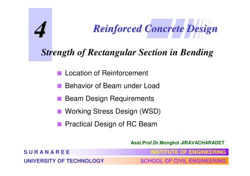
Reinforced Concrete Design
Reinforced Concrete Design
Reinforced Concrete Design

Create successful ePaper yourself
Turn your PDF publications into a flip-book with our unique Google optimized e-Paper software.
4<br />
Strength of Rectangular Section in Bending<br />
S U R A N A R E E<br />
<strong>Reinforced</strong> <strong>Concrete</strong> <strong>Design</strong><br />
Location of Reinforcement<br />
Behavior of Beam under Load<br />
Beam <strong>Design</strong> Requirements<br />
Working Stress <strong>Design</strong> (WSD)<br />
Practical <strong>Design</strong> of RC Beam<br />
UNIVERSITY OF TECHNOLOGY<br />
Asst.Prof.Dr.Mongkol JIRAVACHARADET<br />
INSTITUTE OF ENGINEERING<br />
SCHOOL OF CIVIL ENGINEERING
Location of Reinforcement<br />
<strong>Concrete</strong> cracks due to tension, and as a result, reinforcement is is<br />
required<br />
where flexure, axial loads, or shrinkage effects cause tensile stresses. stresses.<br />
• Simply supported beam<br />
Positive<br />
Moment<br />
tensile stresses and cracks are<br />
developed along bottom of the beam<br />
BMD<br />
longitudinal reinforcement is placed<br />
closed to the bottom side of the beam
• Cantilever beam<br />
- Top bars<br />
- Ties and anchorage<br />
to support<br />
Location of Reinforcement
• Continuous beam<br />
Location of Reinforcement
Location of Reinforcement<br />
• Continuous beam with 2 spans
Figure B-13 : Reinforcement Arrangement for Suspended Beams
Figure B-14 : Reinforcement Arrangement for<br />
Suspended Cantilever Beams
Behavior of Beam under Load<br />
w<br />
Working Stress Condition<br />
L<br />
Elastic Bending (Plain <strong>Concrete</strong>)<br />
ε s<br />
ε f < f = 2.0 f ′<br />
c<br />
εc<br />
εc<br />
f < f ′ c<br />
r c<br />
f < f ′ c<br />
C<br />
T = A s f s
Brittle failure mode<br />
Crushing<br />
Ductile failure mode<br />
εs < εy<br />
εs ≥εy<br />
ε cu = 0.003<br />
fs < fy<br />
ε c < 0.003<br />
fs = fy<br />
C<br />
T = A s f s<br />
C<br />
T = A s f s
Beam <strong>Design</strong> Requirements<br />
1) Minimum Depth (for deflection control)<br />
oneway<br />
slab<br />
L/20<br />
L/24 L/28 L/10<br />
BEAM L/16 L/18.5 L/21 L/8<br />
2) Temperature Steel (for slab)<br />
SR24: A s = 0.0025 bt<br />
SD30: A s = 0.0020 bt<br />
SD40: A s = 0.0018 bt<br />
f y > 4,000 ksc: A s = 0.0018 4,000 bt<br />
f y<br />
t<br />
b<br />
A s
3) Minimum Steel (for beam)<br />
A s min = 14 / f y<br />
To ensure that steel not fail before first crack<br />
4) <strong>Concrete</strong> Covering<br />
5) Bar Spacing<br />
A s<br />
stirrup<br />
กก<br />
ก<br />
Durability and Fire protection<br />
> 4/3 max. aggregate size
WSD of Beam for Moment<br />
Assumptions:<br />
1) Section remains plane<br />
2) Stress proportioned to Strain<br />
3) <strong>Concrete</strong> not take tension<br />
4) No concrete-steel slip<br />
Modular ratio (n):<br />
6<br />
Es<br />
2.04× 10 134<br />
n = = ≈<br />
E 15,100 f ′ f ′<br />
c c c
Effective Depth (d) : Distance from compression face to centroid of steel<br />
Cracked transformed section<br />
compression face<br />
d<br />
b<br />
d<br />
strain condition force equilibrium<br />
εc<br />
fc = Ecε c<br />
kd<br />
C<br />
N.A.<br />
T = A f<br />
ε s s<br />
s<br />
f = E ε<br />
s s s<br />
jd
Compression in concrete:<br />
Equilibrium ΣF x= 0 :<br />
Compression = Tension<br />
1<br />
2<br />
fc b kd = As fs<br />
1<br />
2 c C = f b kd<br />
Tension in steel: T = As fs<br />
Reinforcement ratio: ρ = /<br />
fc<br />
2ρ<br />
f k<br />
s<br />
A bd<br />
s<br />
= 1<br />
kd<br />
fc = Ecε c<br />
C<br />
N.A.<br />
T = A f<br />
s s<br />
f = E ε<br />
s s s<br />
jd
Strain compatibility:<br />
d<br />
kd<br />
ε s<br />
εc<br />
εc<br />
ε<br />
s<br />
kd k<br />
= =<br />
d − kd 1−<br />
k<br />
fc / Ec k<br />
=<br />
f / E 1−<br />
k<br />
s s<br />
fc k<br />
n =<br />
f 1−<br />
k<br />
Analysis: know ρ find k 1 2 ( ) 2<br />
<strong>Design</strong>: know f c , f s find k 2<br />
s<br />
k = 2nρ<br />
+ nρ − nρ<br />
k<br />
2<br />
n fc<br />
1<br />
= =<br />
n f f<br />
c + fs<br />
s 1+<br />
n f<br />
c
Allowable Stresses<br />
Plain concrete:<br />
f = 0.33 f ′ ≤ 60 kg/cm<br />
c c<br />
<strong>Reinforced</strong> concrete:<br />
f = 0.375 f ′ ≤ 65 kg/cm<br />
c c<br />
Example 3.1: f ′ = 150 ksc , fs = 1,500 ksc<br />
c<br />
134<br />
n = = 10.94 ⇒10<br />
(nearest integer)<br />
150<br />
f<br />
c<br />
2<br />
2<br />
= 0.375(150) = 56 ksc<br />
1<br />
k = = 0.2515<br />
1,500<br />
1+ 9(56)<br />
Steel:<br />
SR24: f s = 0.5(2,400) = 1,200 ksc<br />
SD30: f s = 0.5(3,000) = 1,500 ksc<br />
SD40, SD50: f s<br />
= 1,700 ksc
Resisting Moment<br />
M<br />
jd<br />
kd/3<br />
1<br />
2 c C = f k b d<br />
T = A s f s<br />
Steel: M = T × jd = As fs jd<br />
<strong>Concrete</strong>:<br />
Moment arm distance : j d<br />
jd = d −<br />
k<br />
j = 1− 3<br />
1<br />
2 c<br />
M = C × jd = f k j b d = R b d<br />
1<br />
2 c R =<br />
f k j<br />
kd<br />
3<br />
2 2
<strong>Design</strong> Step: known M, f c, f s, n<br />
1) Compute parameters<br />
k<br />
= +<br />
f c<br />
(kg/cm 2 )<br />
45<br />
50<br />
55<br />
60<br />
65<br />
1<br />
f n f<br />
1 s c<br />
n<br />
12<br />
12<br />
11<br />
11<br />
10<br />
j = 1 − k / 3<br />
f s =1,200<br />
(kg/cm 2 )<br />
6.260<br />
7.407<br />
8.188<br />
9.386<br />
10.082<br />
R (kg/cm 2 )<br />
f s =1,500<br />
(kg/cm 2 )<br />
5.430<br />
6.463<br />
7.147<br />
8.233<br />
8.835<br />
1<br />
2 c R = f k j<br />
f s =1,700<br />
(kg/cm 2 )<br />
4.988<br />
5.955<br />
6.587<br />
7.608<br />
8.161
<strong>Design</strong> Parameter k and j<br />
f c<br />
(kg/cm 2 )<br />
45<br />
50<br />
55<br />
60<br />
65<br />
n<br />
12<br />
12<br />
11<br />
11<br />
10<br />
f s =1,200<br />
(kg/cm 2 )<br />
k j<br />
0.310<br />
0.333<br />
0.335<br />
0.355<br />
0.351<br />
0.897<br />
0.889<br />
0.888<br />
0.882<br />
0.883<br />
f s =1,500<br />
(kg/cm 2 )<br />
k j<br />
0.265<br />
0.286<br />
0.287<br />
0.306<br />
0.302<br />
0.912<br />
0.905<br />
0.904<br />
0.898<br />
0.899<br />
f s =1,700<br />
(kg/cm 2 )<br />
k j<br />
0.241<br />
0.261<br />
0.262<br />
0.280<br />
0.277<br />
0.920<br />
0.913<br />
0.913<br />
0.907<br />
0.908<br />
1) For greater f s , k becomes smaller → smaller compression area<br />
2) j ≈ 0.9 → moment arm j d ≈ 0.9d can be used in approximation<br />
design.
2) Determine size of section bd 2<br />
Such that resisting moment of concrete M c = R b d 2 ≥ Required M<br />
Usually b ≈ d / 2 : b = 10 cm, 20 cm, 30 cm, 40 cm, . . .<br />
3) Determine steel area<br />
From<br />
d = 20 cm, 30 cm, 40 cm, 50 cm, . . .<br />
M = A f jd → A =<br />
s s s<br />
4) Select steel bars and Detailing<br />
M<br />
f j d<br />
s
ก.1 ก,<br />
. 2<br />
Bar Dia.<br />
RB6<br />
RB9<br />
DB10<br />
DB12<br />
DB16<br />
DB20<br />
DB25<br />
Number of Bars<br />
1 2 3 4 5 6<br />
0.283<br />
0.636<br />
0.785<br />
1.13<br />
2.01<br />
3.14<br />
4.91<br />
0.565<br />
1.27<br />
1.57<br />
2.26<br />
4.02<br />
6.28<br />
9.82<br />
0.848<br />
1.91<br />
2.36<br />
3.53<br />
6.03<br />
9.42<br />
14.73<br />
1.13<br />
2.54<br />
3.14<br />
4.52<br />
8.04<br />
12.57<br />
19.63<br />
1.41<br />
3.18<br />
3.93<br />
5.65<br />
10.05<br />
15.71<br />
24.54<br />
1.70<br />
3.82<br />
4.71<br />
6.79<br />
12.06<br />
18.85<br />
29.45
ก.3 ก<br />
ACI<br />
Member<br />
One-way slab<br />
Beam<br />
L = span length<br />
Simple<br />
supported<br />
L/20<br />
L/16<br />
One-end<br />
continuous<br />
L/24<br />
L/18.5<br />
Both-ends<br />
continuous Cantilever<br />
L/28<br />
L/21<br />
L/10<br />
For steel with f y not equal 4,000 kg/cm 2 multiply with 0.4 + f y /7,000<br />
L/8
Example 3.2: Working Stress <strong>Design</strong> of Beam<br />
5.0 m<br />
w = 4 t/m<br />
<strong>Concrete</strong>: f c = 65 kg/cm 2<br />
Steel: f s = 1,700 kg/cm 2<br />
From table: n = 10, R = 8.161 kg/cm 2<br />
Required moment strength M = (4) (5) 2 / 8 = 12.5 t-m<br />
Recommended depth for simple supported beam:<br />
d = L/16 = 500/16 = 31.25 cm<br />
USE section 30 x 50 cm with steel bar DB20<br />
d = 50 - 4(covering) - 2.0/2(bar) = 45 cm
Moment strength of concrete:<br />
M c = R b d 2 = 8.161 (30) (45) 2<br />
= 495,781 kg-cm<br />
TRY section 40 x 80 cm d = 75 cm<br />
Steel area:<br />
A<br />
s<br />
=<br />
= 4.96 t-m < 12.5 t-m NG<br />
M c = R b d 2 = 8.161 (40) (75) 2<br />
M<br />
f jd<br />
s<br />
= 1,836,225 kg-cm<br />
= 18.36 t-m > 12.5 t-m OK<br />
=<br />
1,<br />
700<br />
12.<br />
5<br />
×<br />
× 10<br />
0.<br />
908<br />
5<br />
× 75<br />
Select steel bar 4DB20 (A s = 12.57 cm 2 )<br />
=<br />
10.<br />
8<br />
cm<br />
2
Alternative Solution:<br />
From M c = R b d 2 = required moment M<br />
2 M<br />
b d = ⇒ d =<br />
R<br />
M<br />
R b<br />
For example M = 12.5 t-m, R = 8.161 ksc, b = 40 cm<br />
d<br />
5<br />
12.<br />
5 × 10<br />
8.<br />
161 × 40<br />
USE section 40 x 80 cm d = 75 cm<br />
=<br />
=<br />
61.<br />
88<br />
cm
Revised <strong>Design</strong> due to Self Weight<br />
From selected section 40 x 80 cm<br />
Beam weight w bm = 0.4 × 0.8 × 2.4(t/m 3 ) = 0.768 t/m<br />
Required moment M = (4 + 0.768) (5) 2 / 8 = 14.90 < 18.36 t-m OK<br />
Revised <strong>Design</strong> due to Support width<br />
30 cm<br />
Column width 30 cm<br />
4.7 m clear span<br />
5.0 m span<br />
30 cm<br />
Required moment:<br />
M = (4.768) (4.7) 2 / 8<br />
= 13.17 t-m
Practical <strong>Design</strong> of RC Beam<br />
B1 30x60 Mc = 8.02 t-m, Vc = 6.29 t.<br />
w = 2.30 t/m<br />
5.00<br />
Load<br />
dl 0.43<br />
wall 0.63<br />
slab 1.24<br />
w 2.30<br />
M ± = (1/9)(2.3)(5.0) 2 = 6.39 t-m<br />
As ± = 8.62 cm 2 (2DB25)<br />
V = 5.75 t (RB9@0.20 St.)<br />
fc = 65 ksc, fs = 1,500 ksc, n = 10<br />
k = 0.302, j = 0.899, R = 8.835 ksc<br />
b = 30 cm, d = 60 - 5 = 55 cm<br />
Mc = 8.835(30)(55) 2 /10 5 = 8.02 t-m<br />
Vc = 0.29(173) 1/2 (30)(55)/10 3<br />
= 6.29 t<br />
As ± = 6.39×10 5 /(1,500×0.899×55)<br />
= 8.62 cm 2
B2 40x80 Mc = 19.88 t-m, Vc = 11.44 t.<br />
SFD<br />
BMD<br />
As<br />
w = 2.64 t/m<br />
w = 2.64 t/m<br />
8.00 5.00<br />
8.54 9.83<br />
12.58 3.37<br />
+13.81<br />
13.65<br />
3DB25<br />
-16.17<br />
15.99<br />
4DB25<br />
+2.15<br />
2.13<br />
2DB25
GRASP Version 1.02<br />
B11-B12<br />
Membe<br />
r<br />
1<br />
2<br />
3<br />
4<br />
5<br />
6<br />
Mz.i [T-m]<br />
0<br />
-53.42<br />
-37.97<br />
-46.35<br />
-28.26<br />
-92.25<br />
Mz.pos [T-m]<br />
39.03<br />
17.36<br />
20.75<br />
25.88<br />
6.59<br />
81.47<br />
Mz.j [T-m]<br />
-53.42<br />
-37.97<br />
-46.35<br />
-28.26<br />
-92.25<br />
0.00<br />
Fy.i [Ton]<br />
33.04<br />
44.52<br />
40.54<br />
44.96<br />
31.27<br />
69.70<br />
Fy.j [Ton]<br />
-50.84<br />
-39.36<br />
-43.34<br />
-38.92<br />
-52.61<br />
-47.73
Analysis of RC Beam<br />
Given: Section A s , b, d Materials f c , f s<br />
Find: M allow = Moment capacity of section<br />
STEP 1 : Locate Neutral Axis (kd)<br />
2 ( ρn<br />
) n<br />
k = 2ρn<br />
+ − ρ<br />
j = 1 − k<br />
A s<br />
/<br />
3<br />
where ρ =<br />
bd<br />
= Reinforcem ent ratio<br />
Es<br />
n =<br />
E<br />
6<br />
2.04× 10 134<br />
= ≈<br />
15,100 f ′ f ′<br />
c c c
STEP 2 : Resisting Moment<br />
<strong>Concrete</strong>:<br />
1<br />
f<br />
2<br />
Mc = c<br />
Steel: A f j d<br />
Ms s s =<br />
If M c > M s , Over reinforcement M allow = M s<br />
If M c < M s , Under reinforcement M allow = M c<br />
k<br />
Under reinforcement is preferable because steel is weaker<br />
than concrete. The RC beam would fail in ductile mode.<br />
j<br />
b<br />
d<br />
2
Example 3.3 Determine the moment strength of beam<br />
80 cm<br />
40 cm f c = 65 ksc, f s = 1,700 ksc,<br />
4 DB 20<br />
A s = 12.57 cm 2<br />
n = 10, d = 75 cm<br />
12.<br />
57<br />
ρ = = = 0.<br />
00419 , n<br />
bd 40 × 75<br />
k<br />
=<br />
=<br />
A s ρ<br />
2<br />
×<br />
0.<br />
251<br />
0.<br />
0419<br />
→<br />
j<br />
=<br />
+<br />
1<br />
( 0.<br />
0419<br />
−<br />
0.<br />
251<br />
)<br />
/<br />
2<br />
3<br />
−<br />
=<br />
0.<br />
0419<br />
=<br />
0.<br />
916<br />
M c = 0.5(65)(0.251)(0.916)(40)(75) 2 /10 5 = 16.81 t-m<br />
0.<br />
0419<br />
M s = (12.57)(1,700)(0.916)(75)/10 5 = 14.68 t-m (control)
Double Reinforcement<br />
M<br />
When M req’d > M allow<br />
A’ s<br />
A s<br />
d’<br />
ε s<br />
ε c<br />
- Increase steel area<br />
- Enlarge section<br />
- Double RC<br />
only when no choice<br />
ε’ s<br />
T’ = A’ s f’ s<br />
1<br />
C = fc k b d<br />
2<br />
T = A s f s<br />
A s1 f s<br />
A s2 f s
กก<br />
T’ = A’ s f’ s<br />
1<br />
C = fckbd 2<br />
T = A s f s<br />
Moment strength<br />
M = M 1 + M 2<br />
jd<br />
Steel area As = s1<br />
1<br />
C = f<br />
2 ckbd<br />
T 1 = A s1 f s<br />
1<br />
M1 = M c = fckjbd 2<br />
= A f jd<br />
A<br />
s1 s<br />
M<br />
c = + As<br />
2<br />
fs jd<br />
2<br />
2<br />
d-d’<br />
M = M − M<br />
T’ = A’ s f’ s<br />
T 2 = A s2 f s<br />
= As 2 fs ( d − d′<br />
)<br />
= A′ f ′ ( d − d′<br />
)<br />
=<br />
s s<br />
c<br />
M − M c<br />
f ( d − d′<br />
)<br />
s
Compatibility Condition<br />
d<br />
d’<br />
ε c<br />
kd ε’ s<br />
ε s<br />
ε s d − kd<br />
=<br />
ε′<br />
kd − d′<br />
s<br />
From Hook’s law: ε s = E s f s, ε’ s = E s f’ s<br />
Es fs fs d − kd<br />
= =<br />
E f ′ f ′ kd − d′<br />
s s s<br />
f ′ = f<br />
s s<br />
... ก ′ = 2<br />
f f<br />
s s<br />
k − d′ d<br />
1−<br />
k<br />
k − d′ d<br />
1−<br />
k
ก ( A’ s )<br />
d-d’<br />
T’ = A’ s f’ s<br />
T 2 = A s2 f s<br />
′ =<br />
Force equilibrium [ ΣF x=0 ]<br />
T’ = T 2<br />
A’ s f’ s = A s2 f s<br />
f ′ = f<br />
Substitute 2<br />
1 1−<br />
k<br />
As As 2<br />
2 k −<br />
d′ d<br />
s s<br />
k − d′ d<br />
1−<br />
k
ก ( k )<br />
d<br />
d’<br />
ε c<br />
kd ε’ s<br />
ε s<br />
1<br />
2<br />
Compression = Tension<br />
C + C′ = T<br />
c s<br />
f bkd + A′ f ′ = A f<br />
c s s s s<br />
k − d′ d A′<br />
s<br />
Substitute f ′ s = 2 fs<br />
, ρ′<br />
=<br />
1−<br />
k b d<br />
1−<br />
k As<br />
fs = n fc<br />
, ρ =<br />
k b d<br />
⎛ d′<br />
⎞ 2<br />
k = 2n⎜ ρ + 2ρ′ ⎟ + n ρ + 2ρ′ − n ρ + 2ρ′<br />
⎝ d ⎠<br />
2<br />
( ) ( )
Example 3.4 <strong>Design</strong> 40x80 cm beam using double RC<br />
5.0 m<br />
w = 6 t/m<br />
f c = 65 ksc, f s = 1,700 ksc,<br />
n = 10, d = 75 cm<br />
Required M = (6.768) (5) 2 / 8 = 21.15 t-m<br />
k = 0.277, j = 0.908, R = 8.161 ksc<br />
Beam weight w bm = 0.4 × 0.8 × 2.4(t/m 3 ) = 0.768 t/m<br />
M c = Rbd 2 = 8.161(40)(75) 2 /10 5 = 18.36 t-m < req’d M Double RC<br />
A<br />
A<br />
s1<br />
s2<br />
5<br />
M c 18.36× 10<br />
= = = 15.86 cm<br />
f jd 1,700 × 0.908× 75<br />
s<br />
5<br />
M − M c (21.15 − 18.36) × 10<br />
= = = 2.34 cm<br />
f ( d − d′<br />
) 1,700 × (75 −<br />
5)<br />
s<br />
2<br />
2
Tension steel A s = A s1 + A s2 = 15.86 + 2.34 = 18.20 cm 2<br />
USE 6DB20 (A s = 18.85 cm 2 )<br />
Compression steel<br />
1 1− k 1 1− 0.277<br />
′ = = × 2.34× = 4.02 cm<br />
2 − 2 0.277 − 5/ 75<br />
As As 2<br />
k d′ d<br />
USE 2DB20 (A s = 6.28 cm 2 )<br />
0.80 m<br />
0.40 m<br />
2DB20<br />
6DB20<br />
2
175 <br />
3 3