Design Principles - DSPE
Design Principles - DSPE
Design Principles - DSPE

You also want an ePaper? Increase the reach of your titles
YUMPU automatically turns print PDFs into web optimized ePapers that Google loves.
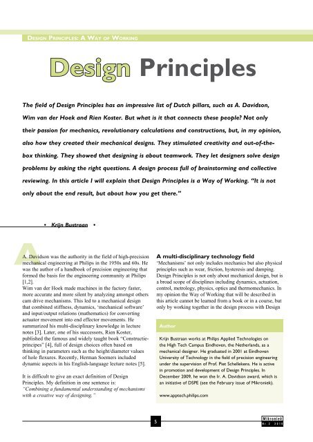
De s i g n PrinciPles: A WA y o f Wo r k i n g<br />
<strong>Design</strong> <strong>Principles</strong><br />
The field of <strong>Design</strong> <strong>Principles</strong> has an impressive list of Dutch pillars, such as A. Davidson,<br />
Wim van der Hoek and Rien Koster. But what is it that connects these people? Not only<br />
their passion for mechanics, revolutionary calculations and constructions, but, in my opinion,<br />
also how they created their mechanical designs. They stimulated creativity and out-of-the-<br />
box thinking. They showed that designing is about teamwork. They let designers solve design<br />
problems by asking the right questions. A design process full of brainstorming and collective<br />
reviewing. In this article I will explain that <strong>Design</strong> <strong>Principles</strong> is a Way of Working. “It is not<br />
only about the end result, but about how you get there.”<br />
• Krijn Bustraan •<br />
AA. Davidson was the authority in the field of high-precision<br />
mechanical engineering at Philips in the 1950s and 60s. He<br />
was the author of a handbook of precision engineering that<br />
formed the basis for the engineering community at Philips<br />
[1,2].<br />
Wim van der Hoek made machines in the factory faster,<br />
more accurate and more silent by analyzing amongst others<br />
cam drive mechanisms. This led to a mechanical design<br />
that combined stiffness, dynamics, ‘mechanical software’<br />
and input/output relations (mathematics) for converting<br />
actuator movement into end effector movements. He<br />
summarized his multi-disciplinary knowledge in lecture<br />
notes [3]. Later, one of his successors, Rien Koster,<br />
published the famous and widely taught book “Constructieprincipes”<br />
[4], full of design choices often based on<br />
thinking in parameters such as the height/diameter values<br />
of hole flexures. Recently, Herman Soemers included<br />
dynamic aspects in his English-language lecture notes [5].<br />
It is difficult to give an exact definition of <strong>Design</strong><br />
<strong>Principles</strong>. My definition in one sentence is:<br />
“Combining a fundamental understanding of mechanisms<br />
with a creative way of designing.”<br />
A multi-disciplinary technology field<br />
‘Mechanisms’ not only includes mechanics but also physical<br />
principles such as wear, friction, hysteresis and damping.<br />
<strong>Design</strong> <strong>Principles</strong> is not only about mechanical design, but is<br />
a broad scope of disciplines including dynamics, actuation,<br />
control, metrology, physics, optics and thermomechanics. In<br />
my opinion the Way of Working that will be described in<br />
this article cannot be learned from a book or in a course, but<br />
only by working together in the design process with <strong>Design</strong><br />
5<br />
Author<br />
Krijn Bustraan works at Philips Applied Technologies on<br />
the High Tech Campus Eindhoven, the Netherlands, as a<br />
mechanical designer. He graduated in 2001 at Eindhoven<br />
University of Technology in the field of precision engineering<br />
under the supervision of Prof. Piet Schellekens. He is active<br />
in promotion and development of <strong>Design</strong> <strong>Principles</strong>. In<br />
December 2009, he won the Ir. A. Davidson award, which is<br />
an initiative of <strong>DSPE</strong> (see the February issue of Mikroniek).<br />
www.apptech.philips.com<br />
Nr.2 2010
De s i g n PrinciPles: A WA y o f Wo r k i n g<br />
<strong>Principles</strong> oriented engineers. Mechanical design is about<br />
teamwork. Use your colleagues as sparring partners to<br />
continuously reflect on your ideas and generate new ones.<br />
<strong>Design</strong>ing together also means putting your ego aside. Stop<br />
the “not invented here” syndrome. In a brainstorm it does<br />
not matter who’s idea it was!<br />
Proposed Way of Working:<br />
include the right concepts by brainstorming<br />
Mechanical designs are mostly not created by sudden<br />
brilliant ideas. Brainstorming can be used to stimulate<br />
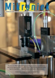
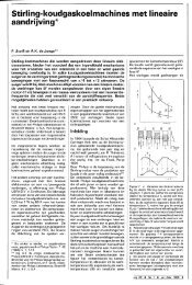
creativity in a systematic way. Figure 1 shows the proposed<br />
systematic Way of Working for design projects with<br />
sufficient complexity. There are five phases in the design<br />
process that always have to be followed: definition,<br />
concept idea, concept design, global design and detailed<br />
design. The phases will be explained in the next section<br />
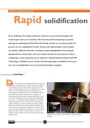
Figure 2. Concept phases with brainstorming and ranking towards a flexible concept design.<br />
Nr.2 2010<br />
6<br />
Figure 1. Proposed Way of<br />
Working in the design process.<br />
about the creation of an opto-mechanical design. Each<br />
phase ends with a review and archiving of the results.<br />
The definition phase is about getting the right<br />
specifications and ranking criteria by interviewing the<br />
client. What is important for the customer, determines the<br />
mindset in the design. This can be for example accuracy,<br />
CoGS (Cost of Goods Sold), reliability, lifetime<br />
(prediction) or easy assembly and maintenance. When the<br />
specifications and ranking criteria from the definition phase<br />
are clear, the concept phase can start.<br />
An important step is to split the concept phase in a concept<br />
idea phase and a concept design phase. Figure 2 shows a<br />
way to come to a flexible concept design using<br />
brainstorming and ranking. This phase is about architecture<br />
and a multi-disciplinary team should be used. Brainstorming<br />
techniques such as mind mapping<br />
help to think out-of-the box and to<br />
enlarge the set of concepts. The<br />
large set of ideas should be<br />
filtered on feasibility and client’s<br />
scope. It is recommended to<br />
compose two or three different<br />
system concepts from all the<br />
ideas: for example A, B and C.<br />
For each concept the design issues<br />
must be written down: α, β, γ.<br />
This gives insight in the<br />
complexity and design effort for<br />
each system concept idea.<br />
After the concept ideas are<br />
ranked, one system concept can<br />
be chosen and the concept idea<br />
phase is finished. To give a<br />
generic example: for Lorentz<br />
actuation, moving coil (A) or<br />
moving magnet (B) can be<br />
chosen. System concept idea A<br />
has design issue water cooling on<br />
the moving world due to energy
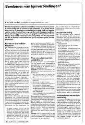
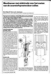
Figure 3. Specifications for an opto-mechanical module.<br />
dissipation in the coils (α) and a cable slab with<br />
disturbance forces varying with stroke (β). System concept<br />
B has a design issue on reaching eigenfrequencies by large<br />
moving weight (δ). Both system concept ideas have a<br />
design issue on magnet stray field (γ).<br />
The concept design phase is to solve the various design<br />
issues for the chosen system concept. The mechanical,<br />
electronical and software teams, for example, can solve<br />
their ‘own’ design issues. For each design issue, the set of<br />
ideas from the brainstorm must be filtered to two or three<br />
concepts (α-a,α-b,α-c). These concepts can be combined in<br />
a morphological chart and will be ranked. The proposed<br />
concept designs should be checked on, for example,<br />
availability, manufacturability, cost and lead time. If<br />
showstoppers arise, the next best concept design can be<br />
chosen without brainstorming again. All the best concept<br />
designs for all design issues together form the proposed<br />
concept design which is reflected to the customer to see if<br />
it is in line with his scope and expectations.<br />
This proposed way of working with doing brainstorms,<br />
expanding the solution space and then narrowing the<br />
number of concepts, leads to a concept design with a large<br />
confidence that the right concept is chosen. Keeping two to<br />
three concepts alive leads to a flexible concept design that<br />
can easily be changed.<br />
Usually a large design effort and many costs are made after<br />
the concept choice: global design, detailed design, detailed<br />
calculations and tests. In my opinion, often too little time is<br />
planned for the concept phase. Choosing the right concept<br />
increases the probability that the global and detailed design<br />
phase can be executed in a straightforward and efficient<br />
way without further iterations.<br />
Example of Way of Working:<br />
creating an opto-mechanical design<br />
Definition phase:<br />
towards specifications and ranking criteria<br />
Figure 3 shows a generic opto-mechanical system<br />
consisting of a periodic plate with a beam array coming<br />
from a substrate as backlight, a lens and a CCD array. The<br />
lens is imaging the periodic plate onto the CCD array. The<br />
components have to be aligned and fixated with respect to<br />
each other with an accuracy of 10 μm. After calibration,<br />
the system has to be robust for (transport) accelerations and<br />
geometrically stable within 100 to 300 nm, see the<br />
positioning accuracy (initial alignment accuracy) and<br />
positioning stability (after calibration) in Figure 3. Other<br />
specifications are a maximum weight of 1 kg, minimum<br />
eigenfrequency of 250 Hz, an ambient temperature range<br />
of 6 °C and transport range temperature. The system will<br />
be made in series of about 100 each year.<br />
7<br />
Nr.2 2010
De s i g n PrinciPles: A WA y o f Wo r k i n g<br />
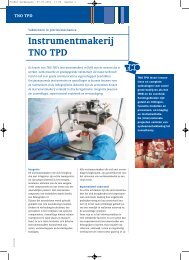
Figure 4. Concept idea phase.<br />
(a) System concept idea. (b) Opto-mechanical module with alignment principle.<br />
The most important criteria for the customer in this case<br />
were: opto-mechanical quality, easy assembly, CoGS and<br />
design lead time. For the design team an added criterion<br />
was design flexibility, since the client had the alignment<br />
tolerances and alignment procedure not ready in this phase.<br />
These criteria were used to rank the concept ideas.<br />
Concept idea phase:<br />
towards system concept ideas<br />
The system concept idea is shown in Figure 4a. It was<br />
created by a multi-disciplinary team of mechanical, optical<br />
and electronical designers and reviewed by the client and<br />
manufacturing and assembly engineers as well. Alternative<br />
system concepts will not be discussed here. The concept<br />
idea is presented as a simple basic picture. In this phase no<br />
CAD design is needed.<br />
The material for three optical components was given: a<br />
fused silica substrate, a quartz lens and a SiC CCD. The<br />
substrate is mounted on a support plate of the same<br />
material to increase rigidity. The material of the periodic<br />
plate was selected as fused silica for thermal expansion<br />
matching. Each (group of) optical component(s) with the<br />
same CTE (Coefficient of Thermal Expansion) is mounted<br />
in an aluminum frame with a thermal center. The outcome<br />
of the system concept idea brainstorm was three possible<br />
materials for the frames: fused silica, stainless steel or<br />
aluminum. Aluminum was chosen for thermal stability, to<br />
obtain homogenous temperatures. Thermal gradients in the<br />
frames or flexures can disturb the positioning stability.<br />
The periodic plate and backlight array were regarded as<br />
one optical component that will be pre-aligned. Then three<br />
frames (subassemblies) were created that have to be<br />
aligned with respect to each other. The frames can be<br />
Nr.2 2010<br />
8<br />
aligned and fixated by aluminum flexures between the<br />
frames, see Figure 4b. A flexible and modular design was<br />
created from conventional frame materials to limit<br />
production lead times and CoGS. The alignment stroke<br />
could be designed in the frames using monolithic structures<br />
with adjustment screws, parallel guides and virtual rotation<br />
points by elastic hinges. However, in this phase the idea<br />
was born to use alignment tooling to reduce product<br />
complexity, cost and weight.<br />
The opto-mechanical module of three subassemblies can be<br />
mounted into a water-cooled mini-environment. The beam<br />
array is activated by electronics on a PCB. From now on,<br />
only the opto-mechanical module will be discussed in<br />
detail as an example to explain the design process phases.<br />
Concept design phase:<br />
towards flexible concept design<br />
The concept design phase is to solve various design issues<br />
one by one by brainstorming in small (mono-disciplinary)<br />
teams. Exploring (hand) calculations can help ranking the<br />
concepts from the brainstorms and to estimate whether the<br />
specifications can be met.<br />
<strong>Design</strong> issues for the opto-mechanical module were<br />
material choices for the frames, the mounting and material<br />
choice of the periodic plate and the alignment and fixation<br />
of the frames.<br />
Starting with the first design issue, thermomechanical<br />
calculations showed that the temperature variations and<br />
gradients within the mini-environment were very small<br />
compared to ambient temperature fluctuations. Hence<br />
stainless steel seemed a better option than aluminum, since<br />
stainless steel flexures have a higher yield strength and no
Figure 5. Brainstorm and ranking on mounting the periodic plate.<br />
Figure 6. Morphological ranking chart.<br />
inserts have to be used for screws. See also Figure 6, where<br />
the frame material choice is ranked with the ranking<br />
criteria.<br />
The design issue of mounting the periodic plate was<br />
tackled with three colleagues and a whiteboard, filtered to<br />
three concepts and archived using simple basic pictures.<br />
The feasible concepts were ranked, see Figure 5: an<br />
integrated fused silica package with the beam array,<br />
mounted on a steel frame within the backlight frame, or<br />
sandwiched. The second concept design was chosen from<br />
the ranking.<br />
The same way of working was followed to tackle all other<br />
design issues. The results were combined in a<br />
morphological ranking chart, see Figure 6. For the periodic<br />
9<br />
plate material stainless<br />
steel or aluminum are not<br />
feasible due to thermal<br />
expansion outside the<br />
stability specification of<br />
0.1 μm. Invar is stable<br />
enough but the<br />
manufacturing process is a<br />
showstopper: the holes<br />
cannot be etched or laser<br />
cut accurately enough<br />
regarding diameter and<br />
positioning. Hence, the<br />
only feasible option<br />
seemed fused silica with an<br />
etched metal (nickel)<br />
coating, although this<br />
option has the lowest<br />
ranking.<br />
Figure 7 shows the concept<br />
design for the optomechanical<br />
module. Note<br />
the differences with the<br />
system concept in Figure 4.<br />
Figure 7. Concept design for the opto-mechanical module<br />
Nr.2 2010
De s i g n PrinciPles: A WA y o f Wo r k i n g<br />
Figure 8. Global design of the opto-mechanical module. Figure 9. Backlight assy with periodic plate.<br />
Global design phase:<br />
towards a principal global design<br />
The global design phase is where the CAD design starts to<br />
fit all parts and functions in the required volume. Geometry<br />
is optimized to balance low weight, high stiffness and<br />
eigenfrequencies on one side, with decoupling for thermal<br />
expansion differences and low alignment stroke forces on<br />
the other side.<br />
Figure 8 shows the global design consisting of three<br />
frames: a backlight assy with the periodic plate mounted on<br />
a separate stainless steel frame and the beam array as<br />
backlight, a lens assy and a CCD assy.<br />
The periodic plate can be glued with beads as spacers onto<br />
the periodic plate frame using a spark-eroded Thermal<br />
Center (TC), see Figure 9.<br />
The backlight assy has to be aligned in three Degrees of<br />
Freedom (DoFs) to the object plane of the lens. The CCD<br />
assy has to be aligned to the image plane of the lens (z, Rx,<br />
Ry) and to the periodic plate (x, y, Rz), a total of six DoFs<br />
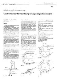
to align. Figure 10 shows the statically determined tooling<br />
interface for alignment in six DoFs. Each frame has three<br />
conical holes that serve as interface for the tooling. The<br />
tooling consists of an external manipulator that is coupled<br />
to the upper and lower frame by three pins with a spherical<br />
front surface. Pin 1 constrains three DoFs, pin 2 constrains<br />
two DoFs by decoupling the horizontal positions for<br />
manufacturing tolerances by an elastic hinge. Pin 3 is<br />
retractable (play-free) and constrains only the z-direction<br />
by using an elastic hinge and radial preload. The six DoFs<br />
alignment can be performed by many different<br />
manipulators, either sourced or by dedicated design.<br />
After alignment the position has to be fixated. Figure 11<br />
shows the three sheet flexures that are used to provide<br />
alignment stroke and exactly constrained fixation after<br />
clamping the flexures using screws.<br />
Nr.2 2010<br />
10<br />
Three possible phenomena can cause fixation errors:<br />
1. Reaction forces of the flexures in bent position will<br />
cause small elastic movements after removing the<br />
alignment tooling.<br />
2. Tool clamping forces can deform the frames, which<br />
will cause small elastic movements after removing the<br />
alignment tooling.<br />
3. Disturbing moments on the frame by screw fixation<br />
torque. When fixating the first of six screws that clamp<br />
the flexures, the screw torque can be led into the frame<br />
and can lead to elastic deformation by finite stiffness of<br />
the tooling.<br />
Ad 1) Fixation errors by flexure reaction forces are<br />
minimized by a high compliance of the flexures, see Figure<br />
11. For the chosen configuration of three flexures at<br />
120 degrees, a uniform horizontal stiffness is obtained of<br />
1.5 times C y’ . This implies that the frame on the flexures<br />
will have an alignment stroke dependent fixation error of<br />
0.8 μm per mm.<br />
Ad 2) The flexures are ‘cut’ to reduce the radial stiffness to<br />
a minimum: 6 N/mm. For 1 mm alignment stroke, pin 3<br />
has to be preloaded with 9 N only.<br />
Ad 3) Screw fixation torque is prevented to be led into the<br />
tooling stiffness by shorting the moment directly into the<br />
flexure. The flexures are clamped into a monolithic sparkeroded<br />
slot. The hold moment between flexure and frame<br />
(on two sides) is always larger than the disturbance<br />
moment between screw head and frame, even for varying<br />
friction coefficients. This way, the frames with optical<br />
components can be constrained in a stress-free and<br />
hysteresis-free way.<br />
Detailed design phase:<br />
towards a robust and cost-effective detailed design<br />
The detailed design is amongst others about robust<br />
tolerance trains and stretching the tolerances. In this case,<br />
for example, the frames holding the optical components<br />
can be water-cut and milled with tolerances of ±0.1 mm.
Figure 10. Exact constrained tooling interface for alignment in six DoFs.<br />
Figure 11. Flexure stiffness ratio C y’ /C x’ = 1 : 1,200; stress level for 1 mm deflection: 440 Mpa.<br />
The only accurate features are the spark-eroded thermal<br />
centers and the flexure clamping blocks. This results in<br />
relatively cost-effective parts.<br />
Summary<br />
<strong>Design</strong> <strong>Principles</strong> is about thinking in Degrees of Freedom,<br />
thinking in functions and parameters, and being creative<br />
and analytical. <strong>Design</strong> <strong>Principles</strong> is also about a Way of<br />
Working using brainstorms and continuously reviewing<br />
design ideas with colleagues. It is not only about the end<br />
result, but about how you get there. A Way of Working<br />
was proposed consisting of five phases with the focus on<br />
concept design. This proposed Way of Working leads to a<br />
concept design with a large confidence that the right<br />
concept is included. Keeping two to three concepts alive<br />
and creating a modular design leads to a flexible design<br />
that can easily be changed if showstoppers arise or if the<br />
client’s scope changes. Choosing the right concept design<br />
accelerates the global and detailed design phase without<br />
further iterations. It leads to a relatively short and<br />
straightforward design process. Ultimately, it may result in<br />
improved customer satisfaction because of shorter time-tomarket<br />
and cost-effective and robust products.<br />
References<br />
[1] A. Davidson, “Handboek van de fijnmechanische<br />
techniek”, Philips technical library, Kluwer, 1968.<br />
[2] A. Davidson, “Handbook of Precision Engineering:<br />
Mechanical design applications”, (Volume 6 of<br />
Handbook of Precision Engineering), McGraw-Hill,<br />
1971.<br />
[3] W. van der Hoek, “Het voorspellen van Dynamisch<br />
gedrag en Positioneringsnauwkeurigheid van<br />
constructies en mechanismen”, lecture notes, 1985.<br />
[4] M.P. Koster, “Constructieprincipes voor het<br />
nauwkeurig bewegen en positioneren”, Twente<br />
University Press and others, 1996-2008.<br />
[5] H.M.J.R. Soemers, “<strong>Design</strong> <strong>Principles</strong> for precision<br />
mechanisms”, lecture notes, University of Twente,<br />
2009.<br />
11<br />
Nr.2 2010