Design Principles - DSPE
Design Principles - DSPE
Design Principles - DSPE

Create successful ePaper yourself
Turn your PDF publications into a flip-book with our unique Google optimized e-Paper software.
De s i g n PrinciPles: A WA y o f Wo r k i n g<br />
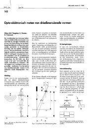
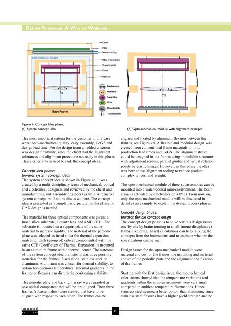
Figure 4. Concept idea phase.<br />
(a) System concept idea. (b) Opto-mechanical module with alignment principle.<br />
The most important criteria for the customer in this case<br />
were: opto-mechanical quality, easy assembly, CoGS and<br />
design lead time. For the design team an added criterion<br />
was design flexibility, since the client had the alignment<br />
tolerances and alignment procedure not ready in this phase.<br />
These criteria were used to rank the concept ideas.<br />
Concept idea phase:<br />
towards system concept ideas<br />
The system concept idea is shown in Figure 4a. It was<br />
created by a multi-disciplinary team of mechanical, optical<br />
and electronical designers and reviewed by the client and<br />
manufacturing and assembly engineers as well. Alternative<br />
system concepts will not be discussed here. The concept<br />
idea is presented as a simple basic picture. In this phase no<br />
CAD design is needed.<br />
The material for three optical components was given: a<br />
fused silica substrate, a quartz lens and a SiC CCD. The<br />
substrate is mounted on a support plate of the same<br />
material to increase rigidity. The material of the periodic<br />
plate was selected as fused silica for thermal expansion<br />
matching. Each (group of) optical component(s) with the<br />
same CTE (Coefficient of Thermal Expansion) is mounted<br />
in an aluminum frame with a thermal center. The outcome<br />
of the system concept idea brainstorm was three possible<br />
materials for the frames: fused silica, stainless steel or<br />
aluminum. Aluminum was chosen for thermal stability, to<br />
obtain homogenous temperatures. Thermal gradients in the<br />
frames or flexures can disturb the positioning stability.<br />
The periodic plate and backlight array were regarded as<br />
one optical component that will be pre-aligned. Then three<br />
frames (subassemblies) were created that have to be<br />
aligned with respect to each other. The frames can be<br />
Nr.2 2010<br />
8<br />
aligned and fixated by aluminum flexures between the<br />
frames, see Figure 4b. A flexible and modular design was<br />
created from conventional frame materials to limit<br />
production lead times and CoGS. The alignment stroke<br />
could be designed in the frames using monolithic structures<br />
with adjustment screws, parallel guides and virtual rotation<br />
points by elastic hinges. However, in this phase the idea<br />
was born to use alignment tooling to reduce product<br />
complexity, cost and weight.<br />
The opto-mechanical module of three subassemblies can be<br />
mounted into a water-cooled mini-environment. The beam<br />
array is activated by electronics on a PCB. From now on,<br />
only the opto-mechanical module will be discussed in<br />
detail as an example to explain the design process phases.<br />
Concept design phase:<br />
towards flexible concept design<br />
The concept design phase is to solve various design issues<br />
one by one by brainstorming in small (mono-disciplinary)<br />
teams. Exploring (hand) calculations can help ranking the<br />
concepts from the brainstorms and to estimate whether the<br />
specifications can be met.<br />
<strong>Design</strong> issues for the opto-mechanical module were<br />
material choices for the frames, the mounting and material<br />
choice of the periodic plate and the alignment and fixation<br />
of the frames.<br />
Starting with the first design issue, thermomechanical<br />
calculations showed that the temperature variations and<br />
gradients within the mini-environment were very small<br />
compared to ambient temperature fluctuations. Hence<br />
stainless steel seemed a better option than aluminum, since<br />
stainless steel flexures have a higher yield strength and no