Design Principles - DSPE
Design Principles - DSPE
Design Principles - DSPE

You also want an ePaper? Increase the reach of your titles
YUMPU automatically turns print PDFs into web optimized ePapers that Google loves.
De s i g n PrinciPles: A WA y o f Wo r k i n g<br />
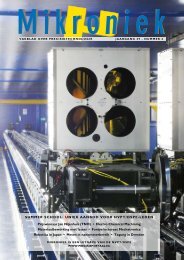
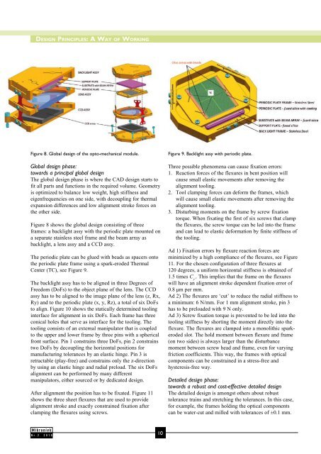
Figure 8. Global design of the opto-mechanical module. Figure 9. Backlight assy with periodic plate.<br />
Global design phase:<br />
towards a principal global design<br />
The global design phase is where the CAD design starts to<br />
fit all parts and functions in the required volume. Geometry<br />
is optimized to balance low weight, high stiffness and<br />
eigenfrequencies on one side, with decoupling for thermal<br />
expansion differences and low alignment stroke forces on<br />
the other side.<br />
Figure 8 shows the global design consisting of three<br />
frames: a backlight assy with the periodic plate mounted on<br />
a separate stainless steel frame and the beam array as<br />
backlight, a lens assy and a CCD assy.<br />
The periodic plate can be glued with beads as spacers onto<br />
the periodic plate frame using a spark-eroded Thermal<br />
Center (TC), see Figure 9.<br />
The backlight assy has to be aligned in three Degrees of<br />
Freedom (DoFs) to the object plane of the lens. The CCD<br />
assy has to be aligned to the image plane of the lens (z, Rx,<br />
Ry) and to the periodic plate (x, y, Rz), a total of six DoFs<br />
to align. Figure 10 shows the statically determined tooling<br />
interface for alignment in six DoFs. Each frame has three<br />
conical holes that serve as interface for the tooling. The<br />
tooling consists of an external manipulator that is coupled<br />
to the upper and lower frame by three pins with a spherical<br />
front surface. Pin 1 constrains three DoFs, pin 2 constrains<br />
two DoFs by decoupling the horizontal positions for<br />
manufacturing tolerances by an elastic hinge. Pin 3 is<br />
retractable (play-free) and constrains only the z-direction<br />
by using an elastic hinge and radial preload. The six DoFs<br />
alignment can be performed by many different<br />
manipulators, either sourced or by dedicated design.<br />
After alignment the position has to be fixated. Figure 11<br />
shows the three sheet flexures that are used to provide<br />
alignment stroke and exactly constrained fixation after<br />
clamping the flexures using screws.<br />
Nr.2 2010<br />
10<br />
Three possible phenomena can cause fixation errors:<br />
1. Reaction forces of the flexures in bent position will<br />
cause small elastic movements after removing the<br />
alignment tooling.<br />
2. Tool clamping forces can deform the frames, which<br />
will cause small elastic movements after removing the<br />
alignment tooling.<br />
3. Disturbing moments on the frame by screw fixation<br />
torque. When fixating the first of six screws that clamp<br />
the flexures, the screw torque can be led into the frame<br />
and can lead to elastic deformation by finite stiffness of<br />
the tooling.<br />
Ad 1) Fixation errors by flexure reaction forces are<br />
minimized by a high compliance of the flexures, see Figure<br />
11. For the chosen configuration of three flexures at<br />
120 degrees, a uniform horizontal stiffness is obtained of<br />
1.5 times C y’ . This implies that the frame on the flexures<br />
will have an alignment stroke dependent fixation error of<br />
0.8 μm per mm.<br />
Ad 2) The flexures are ‘cut’ to reduce the radial stiffness to<br />
a minimum: 6 N/mm. For 1 mm alignment stroke, pin 3<br />
has to be preloaded with 9 N only.<br />
Ad 3) Screw fixation torque is prevented to be led into the<br />
tooling stiffness by shorting the moment directly into the<br />
flexure. The flexures are clamped into a monolithic sparkeroded<br />
slot. The hold moment between flexure and frame<br />
(on two sides) is always larger than the disturbance<br />
moment between screw head and frame, even for varying<br />
friction coefficients. This way, the frames with optical<br />
components can be constrained in a stress-free and<br />
hysteresis-free way.<br />
Detailed design phase:<br />
towards a robust and cost-effective detailed design<br />
The detailed design is amongst others about robust<br />
tolerance trains and stretching the tolerances. In this case,<br />
for example, the frames holding the optical components<br />
can be water-cut and milled with tolerances of ±0.1 mm.