Design Principles - DSPE
Design Principles - DSPE
Design Principles - DSPE

Create successful ePaper yourself
Turn your PDF publications into a flip-book with our unique Google optimized e-Paper software.
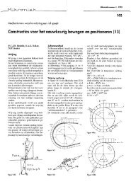
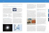
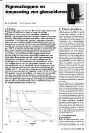
Figure 3. Specifications for an opto-mechanical module.<br />
dissipation in the coils (α) and a cable slab with<br />
disturbance forces varying with stroke (β). System concept<br />
B has a design issue on reaching eigenfrequencies by large<br />
moving weight (δ). Both system concept ideas have a<br />
design issue on magnet stray field (γ).<br />
The concept design phase is to solve the various design<br />
issues for the chosen system concept. The mechanical,<br />
electronical and software teams, for example, can solve<br />
their ‘own’ design issues. For each design issue, the set of<br />
ideas from the brainstorm must be filtered to two or three<br />
concepts (α-a,α-b,α-c). These concepts can be combined in<br />
a morphological chart and will be ranked. The proposed<br />
concept designs should be checked on, for example,<br />
availability, manufacturability, cost and lead time. If<br />
showstoppers arise, the next best concept design can be<br />
chosen without brainstorming again. All the best concept<br />
designs for all design issues together form the proposed<br />
concept design which is reflected to the customer to see if<br />
it is in line with his scope and expectations.<br />
This proposed way of working with doing brainstorms,<br />
expanding the solution space and then narrowing the<br />
number of concepts, leads to a concept design with a large<br />
confidence that the right concept is chosen. Keeping two to<br />
three concepts alive leads to a flexible concept design that<br />
can easily be changed.<br />
Usually a large design effort and many costs are made after<br />
the concept choice: global design, detailed design, detailed<br />
calculations and tests. In my opinion, often too little time is<br />
planned for the concept phase. Choosing the right concept<br />
increases the probability that the global and detailed design<br />
phase can be executed in a straightforward and efficient<br />
way without further iterations.<br />
Example of Way of Working:<br />
creating an opto-mechanical design<br />
Definition phase:<br />
towards specifications and ranking criteria<br />
Figure 3 shows a generic opto-mechanical system<br />
consisting of a periodic plate with a beam array coming<br />
from a substrate as backlight, a lens and a CCD array. The<br />
lens is imaging the periodic plate onto the CCD array. The<br />
components have to be aligned and fixated with respect to<br />
each other with an accuracy of 10 μm. After calibration,<br />
the system has to be robust for (transport) accelerations and<br />
geometrically stable within 100 to 300 nm, see the<br />
positioning accuracy (initial alignment accuracy) and<br />
positioning stability (after calibration) in Figure 3. Other<br />
specifications are a maximum weight of 1 kg, minimum<br />
eigenfrequency of 250 Hz, an ambient temperature range<br />
of 6 °C and transport range temperature. The system will<br />
be made in series of about 100 each year.<br />
7<br />
Nr.2 2010