Gtop Module Application Note -A00 _MT3339 series_.pdf
Gtop Module Application Note -A00 _MT3339 series_.pdf
Gtop Module Application Note -A00 _MT3339 series_.pdf

You also want an ePaper? Increase the reach of your titles
YUMPU automatically turns print PDFs into web optimized ePapers that Google loves.
GlobalTop Technology<br />
GPS <strong>Module</strong> <strong>Application</strong> <strong>Note</strong>s (<strong>MT3339</strong> <strong>series</strong>)<br />
2.2 Layout Guideline<br />
Please follow the layout criteria to design a system using GPS module.<br />
2.2.1 Layout underneath the GPS module<br />
Compatible Mode: SL3C, Gmm-u2p, PA6C, PA6H, Gms-u6b<br />
Ver. <strong>A00</strong><br />
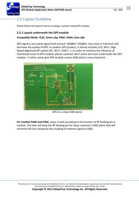
GPS signal is very weak signal level around -160dBm~130dBm. Any noise or harmonic will<br />
decrease the quality of GPS. In modern GPS product, it almost includes LCD, MCU, High<br />
Speed digital and RF system (BT, Wi-Fi, DVB-T…). In order to minimize the influence of<br />
mentioned noise to GPS module, please customer don’t place any trace underneath the GPS<br />
module. In other word, give GPS module a clean GND plane is very important.<br />
GPS on a clean GND plane<br />
For module PA6H and PA6C, place a hold according to the location of RF feeding pin in<br />
module. The hole will keep the RF feeding pin far away customer’s GND plane that will<br />
minimize the loss caused by the coupling of antenna signal to GND.<br />
This document is the exclusive property of GlobalTop Tech Inc. and should not be distributed, reproduced, into any other format without<br />
prior permission of GlobalTop Tech Inc. Specifications subject to change without prior notice.<br />
Copyright © 2012 GlobalTop Technology Inc. All Rights Reserved.<br />
18