Gtop Module Application Note -A00 _MT3339 series_.pdf
Gtop Module Application Note -A00 _MT3339 series_.pdf
Gtop Module Application Note -A00 _MT3339 series_.pdf

You also want an ePaper? Increase the reach of your titles
YUMPU automatically turns print PDFs into web optimized ePapers that Google loves.
GlobalTop Technology<br />
GPS <strong>Module</strong> <strong>Application</strong> <strong>Note</strong>s (<strong>MT3339</strong> <strong>series</strong>)<br />
2. General Rules for Design-in<br />
Ver. <strong>A00</strong><br />
In order to obtain good GPS performances, there are some rules which require attentions for using<br />
GPS module.<br />
2.1 Circuit Design<br />
Compatible Mode: SL3C, Gmm-u2p, PA6C, PA6H, Gms-u6b<br />
2.1.1 Power supply VCC<br />
It is necessary to provide a clean and stable power supply for our GPS module in order to obtain<br />
good performances. Unstable power source will have a significant negative impact on the GPS<br />
performance. To achieve this, the Vcc ripple must be controlled under 50mVpp. In addition, there are<br />
also some important suggestions for main power circuit design:<br />
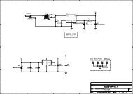
(1). Add ferrite bead, power choke or low pass filter for power noise reduction<br />
(2). linear regulator is better than switch DC/DC power supplier in ripple<br />
(3). Use enough decoupling capacitors beside VCC for stable voltage.<br />
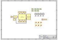
Power design for GPS module<br />
This document is the exclusive property of GlobalTop Tech Inc. and should not be distributed, reproduced, into any other format without<br />
prior permission of GlobalTop Tech Inc. Specifications subject to change without prior notice.<br />
Copyright © 2012 GlobalTop Technology Inc. All Rights Reserved.<br />
7