Gtop Module Application Note -A00 _MT3339 series_.pdf
Gtop Module Application Note -A00 _MT3339 series_.pdf
Gtop Module Application Note -A00 _MT3339 series_.pdf

You also want an ePaper? Increase the reach of your titles
YUMPU automatically turns print PDFs into web optimized ePapers that Google loves.
GlobalTop Technology<br />
GPS <strong>Module</strong> <strong>Application</strong> <strong>Note</strong>s (<strong>MT3339</strong> <strong>series</strong>)<br />
2.2.5 Ground Segmentation<br />
Compatible Mode: SL3C, Gmm-u2p, PA6C, PA6H, Gms-u6b<br />
Ver. <strong>A00</strong><br />
The separation of ground between GPS module and the rest of the system is recommended to avoid<br />
interference. If this is not possible, it is best to follow these typical rules: segmentation of ground<br />
between digital and analogue system, high current and low current system, and different radiation<br />
systems in general (such as GPS and GPRS).<br />
One way to segment the ground is to place digital and noise component at one corner of the board,<br />
while placing analog and quiet components at the opposite corner of the board. Make sure there is<br />
no crossing of microstrip or current between the two component sets and grounds of each sets are<br />
contacted in one point only.<br />
Another way to do this is the place the two different sets at different layers of the board, while the<br />
ground of each layer is contacted in one point only (preferable at border of the board).<br />
2.2.6 Ground Plane<br />
Compatible Mode: PA6C, PA6H, Gms-u6b<br />
For PA6C and PA6H, a large GND plane direct underneath the module could enhance the magneticfield<br />
line of the antenna for better GPS signal reception. Typical it will improve ~2dB as maximum.<br />
It is strongly recommended to have a ground plane designed underneath the GPS module as big as<br />
possible.<br />
The recommended thickness for the ground layer is 0.5 to 1 OZ (0.0175 to 0.035 mm)<br />
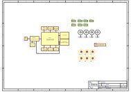
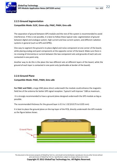
It is best to place the ground plane on the top layer of the PCB, directly underneath the GPS module<br />
as the figure below shows:<br />
This document is the exclusive property of GlobalTop Tech Inc. and should not be distributed, reproduced, into any other format without<br />
prior permission of GlobalTop Tech Inc. Specifications subject to change without prior notice.<br />
Copyright © 2012 GlobalTop Technology Inc. All Rights Reserved.<br />
22