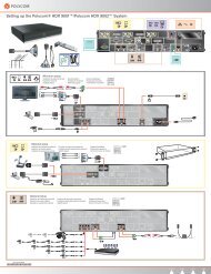
Polycom ViewStation User Guide - Vidofon
Polycom ViewStation User Guide - Vidofon
Polycom ViewStation User Guide - Vidofon

Create successful ePaper yourself
Turn your PDF publications into a flip-book with our unique Google optimized e-Paper software.
<strong>ViewStation</strong> <strong>User</strong> <strong>Guide</strong><br />
<strong>ViewStation</strong> <strong>User</strong> <strong>Guide</strong><br />
November 2001 Edition<br />
3725-10755-001
Important Information<br />
Warning<br />
Other Restrictions<br />
Trademark Information<br />
Patent Information<br />
Warranty<br />
© 2001 <strong>Polycom</strong>, Inc. All rights reserved.<br />
No part of this document may be reproduced or transmitted in any form or by any means, electronic or<br />
mechanical, for any purpose, without the express written permission of <strong>Polycom</strong>, Inc. Under the law,<br />
reproducing includes translating into another language or format.<br />
As between the parties, <strong>Polycom</strong>, Inc. retains title to, and ownership of, all proprietary rights with respect<br />
to the software contained within its products. The software is protected by United States copyright laws<br />
and international treaty provision. Therefore, you must treat the software like any other copyrighted<br />
material (e.g, a book or sound recording).<br />
This is a Class A product. In a domestic environment, this product may cause radio interference, in which<br />
case the user may be required to take adequate measures.<br />
You shall not allow any third party to 1) decompile, disassemble, or otherwise reverse- engineer or attempt<br />
to reconstruct or discover any source code or underlying ideas or algorithms of the software by any means<br />
whatsoever or 2) remove any product.<br />
<strong>Polycom</strong>®, ShowStation®, and the <strong>Polycom</strong> logo design are registered trademarks, and <strong>ViewStation</strong> is<br />
a trademark of <strong>Polycom</strong>, Inc. in the United States and various other countries. ADTRAN® is a registered<br />
trademark and Expert ISDN is a trademark of ADTRAN, Inc. All other trademarks are the property of<br />
their respective owners. Every effort has been made to ensure that the information in this manual is<br />
accurate. <strong>Polycom</strong>, Inc. is not responsible for printing or clerical errors. Information in this document is<br />
subject to change without notice.<br />
The accompanying product is protected by one or more U.S. and foreign patents and patents pending held<br />
by <strong>Polycom</strong>, Inc.<br />
<strong>Polycom</strong>, Inc. warrants its products to be free of defects in materials and factory workmanship for a period<br />
of thirty-six (36) months from date of purchase. This warranty does not apply to damage to products<br />
resulting from accident, misuse, service, or modification by anyone other than a <strong>Polycom</strong>, Inc. authorized<br />
service facility/dealer. The warranty is limited to the original purchaser and is not transferable. Any<br />
liability of <strong>Polycom</strong>, Inc. or its suppliers with respect to the product or the performance thereof under any<br />
warranty, negligence, strict liability, or other theory will be limited exclusively to product repair or<br />
replacement as provided above. Except for the foregoing, the product is provided “as is” without warranty<br />
of any kind including, without limitation, any warranty of merchantability or fitness for a particular<br />
purpose. The entire risk of the quality and performance of the software programs contained in the system<br />
is with you.<br />
Limitation of Remedies and Damages<br />
<strong>Polycom</strong>, Inc., its agents, employees, suppliers, dealers, and other authorized representatives shall not be<br />
responsible or liable with respect to the product or any other subject matter related thereto under any<br />
contract, negligence, strict liability, or other theory for any indirect, incidental, or consequential damages,<br />
including, but not limited to, loss of information, business, or profits.<br />
The law of certain states or nations does not permit limitation or exclusion of implied warranties and<br />
consequential damages, so the above limitations, disclaimers, or exclusion may not apply to you. This<br />
warranty gives you special legal rights. You may also have other rights that vary by state and nation.
Important Safeguards<br />
Regulatory Notices<br />
Read and understand the following instructions before using the system:<br />
• Close supervision is necessary when the system is used by or near children. Do not leave unattended<br />
while in use.<br />
• Only use electrical extension cords with a current rating at least equal to that of the system.<br />
• Always disconnect the system from power before cleaning and servicing and when not in use.<br />
• Do not spray liquids directly onto the system when cleaning. Always apply the liquid first to a<br />
static-free cloth.<br />
• Do not immerse the system in any liquid or place any liquids on it.<br />
• Do not disassemble this system (except as instructed in the manufacturer's instructions). To reduce the<br />
risk of shock and to maintain the warranty on the system, a qualified technician must perform service<br />
or repair work.<br />
• Connect this appliance to a grounded outlet.<br />
• In case of lightning storms, disconnect the telephone line cord from the system, and only connect the<br />
system to surge-protected power outlets.<br />
• Keep ventilation openings free of any obstructions.<br />
• SAVE THESE INSTRUCTIONS.<br />
Plug Acts as Disconnect Device<br />
The socket outlet to which this apparatus is connected must be installed near the equipment and must<br />
always be readily accessible.<br />
FCC Notice<br />
This equipment has been tested and found to comply with the limits for a Class A digital device, pursuant<br />
to Part 15 of the FCC Rules. These limits are designed to provide reasonable protection against harmful<br />
interference when the equipment is operated in a commercial environment. This equipment generates,<br />
uses, and can radiate radio frequency energy and, if not installed and used in accordance with the<br />
instruction manual, may cause harmful interference to radio communications. Operation of this equipment<br />
in a residential area is likely to cause harmful interference, in which case the user will be required to<br />
correct the interference at his own expense.<br />
Changes or modifications not expressly approved by <strong>Polycom</strong> could void the user's authority to operate<br />
this equipment.<br />
• This equipment complies with Part 68 of the FCC Rules. On the bottom of this equipment is a label<br />
that contains, among other information, the FCC registration number and Ringer Equivalence Number<br />
(REN) for this equipment. If requested, provide this information to your telephone company.<br />
• Before connecting your unit, you must inform your telephone company of the following information:<br />
Port ID REN/SOC USOC<br />
Loop Start (“POTS” Port) 0.5 RJ11C<br />
• FCC compliant telephone cords and modular plugs are provided with this equipment. This equipment<br />
is designed to be connected to the telephone network or premises’ wiring using a compatible modular<br />
jack, which is Part 68 compliant. See installation instructions for details.<br />
• The REN is useful to determine the quantity of devices that may be connected to the telephone line.<br />
Excessive REs on the telephone line may result in the devices not ringing in response to an incoming<br />
call. In most, but not all areas, the sum of REs of all devices that may be connected to a line, as<br />
determined by the total RENs, contact the local telephone company.<br />
• If your <strong>ViewStation</strong> causes harm to the telephone network, the telephone company will notify you in<br />
advance that temporary discontinuance of service may be required. However, if advance notice is not<br />
practical, you will be notified as soon as possible. You will be advised of your right to file a complaint<br />
with the FCC if you believe it is necessary.
• Your telephone company may make changes in its facilities, equipment, operations, or procedures that<br />
could affect the operation of your equipment. If they do, you will be given advance notice so as to give<br />
you an opportunity to maintain uninterrupted service.<br />
• If you experience trouble with this equipment, <strong>ViewStation</strong>, please contact your equipment provider<br />
for repair/warranty information. If your equipment is causing harm to the telephone network, the<br />
telephone company may request that you disconnect the equipment until the problem is resolved.<br />
• There are no user-serviceable parts inside the videoconferencing unit, remote control, microphone pod,<br />
or power supply.<br />
• This equipment may not be used on a public coin service provided by the telephone company.<br />
Connection to party lines is subject to state tariffs. Contact your state public utility commission or<br />
corporation commission for information.<br />
Underwriters Laboratories Statement<br />
The system is intended to be powered only by the accompanying power supply unit.<br />
CE Mark R&TEE Directive:<br />
This <strong>ViewStation</strong> and <strong>ViewStation</strong> product line has been marked with the CE mark. This mark indicates<br />
compliance with EEC Directives 89/336/EEC, 73/23/EEC 1999/5/EC. A full copy of the Declaration of<br />
Conformity can be obtained from <strong>Polycom</strong> Ltd. 270 Bath Road, Slough UK, SL1 4DX.<br />
Declaration of Conformity:<br />
Hereby, <strong>Polycom</strong>, Ltd. declares that this <strong>ViewStation</strong> and <strong>ViewStation</strong> product line is in compliance with<br />
the essential requirements and other relevant provisions of Directive 1999/5/EC.<br />
Konformitetserklæring:<br />
Hermed erklærer <strong>Polycom</strong>, Ltd., at indestående <strong>ViewStation</strong> and <strong>ViewStation</strong> product line er i<br />
overensstemmelse med de grundlæggende krav og de relevante punkter i direktiv 1999/5/EF.<br />
Konformitätserklärung:<br />
Hiermit erklärt <strong>Polycom</strong>. Ltd., dass der <strong>ViewStation</strong> and <strong>ViewStation</strong> product line die grundlegenden<br />
Anforderungen und sonstige maßgebliche Bestimmungen der Richtlinie 1999/5/EG erfüllt.<br />
Vaatimustenmukaisuusvakuutus:<br />
<strong>Polycom</strong>, Ltd. vakuuttaa täten, että <strong>ViewStation</strong> and <strong>ViewStation</strong> product line on direktiivin 1999/5/EC<br />
keskeisten vaatimusten ja sen muiden tätä koskevien säännösten mukainen.<br />
Déclaration de conformité :<br />
Par la présente, <strong>Polycom</strong>, Ltd. déclare que ce <strong>ViewStation</strong> and <strong>ViewStation</strong> product line est conforme aux<br />
conditions essentielles et à toute autre modalité pertinente de la Directive 1999/5/CE.<br />
Dichiarazione di conformità:<br />
Con la presente <strong>Polycom</strong>, Ltd. dichiara che il <strong>ViewStation</strong> and <strong>ViewStation</strong> product line soddisfa i<br />
requisiti essenziali e le altre disposizioni pertinenti della direttiva 1999/5/CE.<br />
Verklaring van overeenstemming:<br />
Hierbij verklaart <strong>Polycom</strong>, Ltd. dat diens <strong>ViewStation</strong> and <strong>ViewStation</strong> product line voldoet aan de<br />
basisvereisten en andere relevante voorwaarden van EG-richtlijn 1999/5/EG.<br />
Declaração de Conformidade:<br />
Através da presente, a <strong>Polycom</strong>, Ltd. declara que este <strong>ViewStation</strong> and <strong>ViewStation</strong> product line se<br />
encontra em conformidade com os requisitos essenciais e outras disposições relevantes da Directiva<br />
1999/5/CE.
Declaración de conformidad:<br />
Por la presente declaración, <strong>Polycom</strong>, Ltd. declara que este <strong>ViewStation</strong> and <strong>ViewStation</strong> product line<br />
cumple los requisitos esenciales y otras cláusulas importantes de la directiva 1999/5/CE.<br />
Överensstämmelseförklaring:<br />
<strong>Polycom</strong>, Ltd. förklarar härmed att denna <strong>ViewStation</strong> and <strong>ViewStation</strong> product line överensstämmer<br />
med de väsentliga kraven och övriga relevanta stadganden i direktiv 1999/5/EG.<br />
Omnitel Statement<br />
THE SOFTWARE PROGRAMS CONTAINED OR DESCRIBED HEREIN ARE CONFIDENTIAL<br />
INFORMATION AND PROPRIETARY PRODUCTS OF POLYCOM OR ITS LICENSORS.
Contents<br />
Preface — How To Use This <strong>Guide</strong><br />
<strong>ViewStation</strong> Basics........................................................................................... xiv<br />
Usability Conventions.......................................................................... xv<br />
Getting Started<br />
What You Need to Get Started ........................................................................ 1<br />
Power Source...................................................................................... 2<br />
NT-1 Device ........................................................................................ 2<br />
What’s in the Box ............................................................................................. 2<br />
Using the Remote Control................................................................................ 3<br />
Setting Up the <strong>ViewStation</strong> .............................................................................. 3<br />
Connecting the <strong>ViewStation</strong> to the ISDN or DCP Network ................. 4<br />
<strong>ViewStation</strong> H.323 with Quad BRI ......................................... 5<br />
<strong>ViewStation</strong> H.323 with Avaya DCP....................................... 5<br />
<strong>ViewStation</strong> 128 ..................................................................... 6<br />
Connecting the <strong>ViewStation</strong> H.323 with V.35 to a Network ................ 7<br />
Connecting the V.35 Network Interface Module to<br />
the <strong>ViewStation</strong> ...................................................................... 7<br />
Connecting the V.35 Network Interface Module to<br />
the V.35 DCE ......................................................................... 7<br />
Connecting the <strong>ViewStation</strong> to an Ethernet LAN ................................ 8<br />
Initial System Configuration ............................................................................. 9<br />
Setup Common to all <strong>ViewStation</strong>s..................................................... 9<br />
Network Status Indicators ................................................................................ 26<br />
Using the <strong>ViewStation</strong> Help.............................................................................. 28<br />
Using <strong>ViewStation</strong> Help....................................................................... 28<br />
Technical Support ............................................................................... 29<br />
Optional Configurations<br />
<strong>User</strong> Setup ....................................................................................................... 31<br />
Admin Setup..................................................................................................... 34<br />
General Setup ..................................................................................... 35<br />
Video Network..................................................................................... 39<br />
<strong>ViewStation</strong> H.323 with Quad BRI ......................................... 39<br />
<strong>ViewStation</strong> H.323 with Avaya DCP....................................... 47<br />
<strong>ViewStation</strong> 128 ..................................................................... 54<br />
<strong>ViewStation</strong> H.323 with V.35.................................................. 57<br />
LAN/H.323........................................................................................... 64<br />
LAN/Internet ........................................................................... 64<br />
© <strong>Polycom</strong>, Inc. vii <strong>ViewStation</strong> <strong>User</strong> <strong>Guide</strong>
H.323 Setup ........................................................................... 66<br />
Gateway ................................................................................. 69<br />
Gatekeeper............................................................................. 70<br />
Dialing Speeds ....................................................................... 71<br />
Quality of Service (QoS) and Firewalls .................................. 72<br />
SNMP ..................................................................................... 73<br />
Global Address....................................................................... 75<br />
Global Management ............................................................................ 84<br />
GMS Setup............................................................................. 85<br />
Global Management Information ............................................ 87<br />
Data Conference ................................................................................. 87<br />
Telephone & Audio.............................................................................. 88<br />
Video/Camera ..................................................................................... 90<br />
Security ............................................................................................... 93<br />
Software/Hardware.............................................................................. 95<br />
Software Information .............................................................. 95<br />
Hardware Information............................................................. 96<br />
System Options ...................................................................... 96<br />
Using the <strong>ViewStation</strong><br />
Placing and Answering Calls............................................................................ 97<br />
Main Calling Screen ............................................................................ 97<br />
<strong>ViewStation</strong> Network Line Indicators...................................... 98<br />
Placing a Video Call ............................................................................ 99<br />
Placing a Video Call Manually................................................ 100<br />
Placing a Video Call Using Speed Dial .................................. 102<br />
Placing a Video Call From the Web lnterface......................... 104<br />
Using the Address Book...................................................................... 104<br />
Adding New Entries to the Address Book .............................. 104<br />
Editing an Existing Entry in the Address Book ....................... 107<br />
Deleting an Entry from the Address Book .............................. 108<br />
Transferring an Address Book................................................ 109<br />
Using the Global Address Book .......................................................... 110<br />
Using Multi-Point Address Book Entries................................. 110<br />
Placing a Video Call Using the Address Book........................ 111<br />
Placing a Video Call from the Web Interface.......................... 112<br />
Placing Telephone Calls with the <strong>ViewStation</strong> ................................................. 113<br />
Placing a Telephone Call .................................................................... 113<br />
Answering a Video Call ....................................................................... 114<br />
Manual.................................................................................... 114<br />
Auto-Answer........................................................................... 114<br />
Placing Multi-Point Calls (<strong>ViewStation</strong> MP Only) ................................ 114<br />
Adding a Telephone Call to a Video Call............................................. 116<br />
<strong>ViewStation</strong> <strong>User</strong> <strong>Guide</strong> viii www.polycom.com
Multi-Point Viewing Modes............................................................................... 118<br />
Using Chair Control in a Multi-Point Call............................................. 119<br />
Using a <strong>ViewStation</strong> with a StreamStation....................................................... 121<br />
Starting a Webcast.............................................................................. 122<br />
Ending a Webcast ............................................................................... 123<br />
Displaying ChatBack Messages.......................................................... 124<br />
Adjusting Cameras and Sound ........................................................................ 125<br />
Selecting <strong>ViewStation</strong> Cameras.......................................................... 125<br />
Pan, Tilt, and Zoom for the <strong>ViewStation</strong> Camera................................ 127<br />
Setting Camera Presets ...................................................................... 127<br />
Automatic Voice Tracking ................................................................... 128<br />
Automatic Tracking of Camera Presets .............................................. 128<br />
Adjusting Sound .................................................................................. 129<br />
Positioning Microphone Pods.............................................................. 129<br />
Sending Snapshots .......................................................................................... 129<br />
Snapshot Timeout ............................................................................... 130<br />
Using Optional Equipment ............................................................................... 130<br />
Using the <strong>ViewStation</strong> with a PC<br />
Connecting The PC to a LAN Through the <strong>ViewStation</strong> .................................. 134<br />
PC Network Properties........................................................................ 135<br />
Connecting The <strong>ViewStation</strong> to a Stand-Alone PC.......................................... 136<br />
Using the <strong>ViewStation</strong> Web Interface............................................................... 139<br />
Select and View a Presentation .......................................................... 139<br />
Sending Snapshots to the <strong>ViewStation</strong> ............................................... 145<br />
Viewing Snapshots from the <strong>ViewStation</strong> ........................................... 145<br />
Closed Caption.................................................................................... 146<br />
Accessing and Using Closed Caption .................................... 146<br />
Usage Information and Restrictions About Closed Caption ... 147<br />
Using Microsoft NetMeeting ............................................................ 147<br />
NetMeeting Application Sharing............................................. 149<br />
H.323 Video Calls with NetMeeting........................................ 149<br />
System Information and Remote Management................................... 149<br />
Placing a Call from the <strong>ViewStation</strong> Web Interface................ 150<br />
<strong>ViewStation</strong> Web Interface Icons ........................................................ 153<br />
<strong>ViewStation</strong> Software....................................................................................... 165<br />
Downgrading Software........................................................................ 165<br />
Upgrading Software ............................................................................ 165<br />
Upgrading Software over ISDN.............................................. 165<br />
Upgrading Software over the LAN ......................................... 166<br />
Using Visual Concert PC.................................................................................. 168<br />
© <strong>Polycom</strong>, Inc. ix <strong>ViewStation</strong> <strong>User</strong> <strong>Guide</strong>
System Information and Diagnostics<br />
System Information .......................................................................................... 171<br />
Diagnostics....................................................................................................... 172<br />
Network Stats ...................................................................................... 173<br />
Advanced Stats ................................................................................... 173<br />
Call Status ........................................................................................... 173<br />
Color Bar ............................................................................................. 174<br />
Audio ................................................................................................... 174<br />
Near End Loop .................................................................................... 174<br />
Far End Loop....................................................................................... 174<br />
Reset System ...................................................................................... 175<br />
Troubleshooting<br />
General Problems ............................................................................................ 177<br />
Audio ................................................................................................................ 178<br />
Video ................................................................................................................ 180<br />
Network and Communications ......................................................................... 182<br />
IMUX ................................................................................................................ 184<br />
LAN/Intranet ..................................................................................................... 185<br />
Presentations ................................................................................................... 186<br />
System Control................................................................................................. 188<br />
Network Address Translation<br />
Before You Start Configuring NAT ................................................................... 189<br />
Setting up NAT................................................................................................. 189<br />
Video and Audio Input and Output Levels<br />
Video Levels..................................................................................................... 191<br />
Video Output Levels ............................................................................ 191<br />
Video Input Levels............................................................................... 191<br />
Audio Levels..................................................................................................... 191<br />
Audio Output Levels ............................................................................ 191<br />
Audio Input Levels............................................................................... 192<br />
V.35 Technical Information<br />
General V.35 Information ................................................................................. 193<br />
Serial Interface Control Signals........................................................... 193<br />
State Machine ..................................................................................... 194<br />
<strong>ViewStation</strong> <strong>User</strong> <strong>Guide</strong> x www.polycom.com
Dial Out State Machine ....................................................................... 194<br />
In-bound Call State Machine............................................................... 195<br />
Nondialed <strong>User</strong>-Initiated Call State Machine ...................................... 197<br />
Nondialed Network-Initiated Call State Machine................................. 198<br />
Crypto Resync..................................................................................... 199<br />
V.35 Cabling Diagram and Schematic ............................................................ 200<br />
ISDN Information<br />
Sample NT-1 Settings...................................................................................... 203<br />
ISDN Switches ................................................................................................. 205<br />
ISDN Errors...................................................................................................... 205<br />
Optional Equipment Configuration<br />
StreamStation Configuration............................................................................ 211<br />
Using a ShowStation IP .................................................................................. 213<br />
Glossary<br />
ABC.................................................................................................................. 215<br />
DEF.................................................................................................................. 218<br />
GHIJK............................................................................................................... 221<br />
LMN.................................................................................................................. 224<br />
OPQ ................................................................................................................. 225<br />
RST.................................................................................................................. 226<br />
UVW................................................................................................................. 227<br />
XYZ .................................................................................................................. 228<br />
Index..........................................................................................................................229<br />
© <strong>Polycom</strong>, Inc. xi <strong>ViewStation</strong> <strong>User</strong> <strong>Guide</strong>
<strong>ViewStation</strong> <strong>User</strong> <strong>Guide</strong> xii www.polycom.com
Preface — How To Use This <strong>Guide</strong><br />
Preface — How To Use This <strong>Guide</strong><br />
Thank you for purchasing a <strong>Polycom</strong> <strong>ViewStation</strong>! Soon you will<br />
discover that video communications using the <strong>ViewStation</strong> is easy,<br />
fun, and productive. <strong>Polycom</strong> <strong>ViewStation</strong>s are the most easy to use<br />
video communications systems on the market today.<br />
This <strong>User</strong> <strong>Guide</strong> provides information about setting up and using the<br />
following <strong>Polycom</strong> <strong>ViewStation</strong> products:<br />
• <strong>ViewStation</strong> H.323 with stand-alone IP<br />
• <strong>ViewStation</strong> H.323 with a Quad BRI network interface module<br />
• <strong>ViewStation</strong> 128 with single ISDN<br />
• <strong>ViewStation</strong> H.323 with a V.35 network interface module<br />
• <strong>ViewStation</strong> H.323 with Avaya DCP network interface module<br />
• <strong>ViewStation</strong> MP — <strong>ViewStation</strong> with Quad BRI or Avaya DCP<br />
with Multi-Point enabled software.<br />
If you purchased a <strong>ViewStation</strong> SP or <strong>ViewStation</strong> SP384, see the<br />
<strong>ViewStation</strong> SP or SP384 <strong>User</strong> <strong>Guide</strong>.<br />
If you purchased a <strong>ViewStation</strong> FX or VS4000, see the <strong>ViewStation</strong><br />
FX and VS4000 <strong>User</strong> <strong>Guide</strong>.<br />
Each <strong>ViewStation</strong> product has a document called a QuickStart card,<br />
which is shipped in the box with your <strong>ViewStation</strong>. The QuickStart<br />
card illustrates how to connect the required cables and optional<br />
equipment to the <strong>ViewStation</strong>.<br />
© <strong>Polycom</strong>, Inc. xiii <strong>ViewStation</strong> <strong>User</strong> <strong>Guide</strong>
<strong>ViewStation</strong> Basics<br />
Preface — How To Use This <strong>Guide</strong><br />
The Graphic <strong>User</strong> Interface (GUI) is designed for ease of use. The<br />
following table is a definition of key icon functions:<br />
Icon Icon Name Function<br />
Text Tab<br />
Select Button<br />
Network Connectivity Error<br />
Call Speed Indicators<br />
Network Line Indicator<br />
The purpose of the Text Tab is<br />
to enable the user to enter<br />
alphanumeric characters into<br />
the <strong>ViewStation</strong>. Numbers are<br />
entered with the remote control.<br />
To enter alpha characters press<br />
the SELECT button on the<br />
remote control.<br />
The SELECT button shown is<br />
on the remote control.<br />
The Network Connectivity<br />
Error icon indicates severe<br />
packet loss between the near<br />
end and the far end<br />
<strong>ViewStation</strong>s.<br />
The Call Speed Indicators<br />
illustrate the call speed of the<br />
near end or the far end<br />
<strong>ViewStation</strong>. Speeds may be set<br />
from the Dialing Speeds<br />
screen. See Dialing Speeds on<br />
page 71.<br />
The Network Line Indicators are<br />
shown when the <strong>ViewStation</strong> is<br />
powered on.<br />
Yellow Box: Checking line<br />
status<br />
Red Down Arrow: Error in<br />
network link<br />
Green Up Arrow: Line is<br />
connected<br />
<strong>ViewStation</strong> <strong>User</strong> <strong>Guide</strong> xiv www.polycom.com
Usability Conventions<br />
Preface — How To Use This <strong>Guide</strong><br />
This guide uses navigational conventions to make <strong>ViewStation</strong><br />
setup and troubleshooting easy. These conventions are marked in<br />
BOLD for each screen followed by a greater than symbol (>) to<br />
indicate navagation. Figure A is an example of this convention.<br />
To view the <strong>User</strong> Setup options, go to System Info > <strong>User</strong> Setup.<br />
Figure A: Conventions Flow Example<br />
© <strong>Polycom</strong>, Inc. xv <strong>ViewStation</strong> <strong>User</strong> <strong>Guide</strong>
Preface — How To Use This <strong>Guide</strong><br />
<strong>ViewStation</strong> <strong>User</strong> <strong>Guide</strong> xvi www.polycom.com
Getting Started<br />
What You Need to Get Started<br />
1<br />
This chapter explains what you need to get started, what’s in the<br />
box, how to use the remote control, how to up the <strong>ViewStation</strong>, how<br />
to configure the <strong>ViewStation</strong> for a specific network interface, and<br />
how to use <strong>ViewStation</strong> help.<br />
The following items are required:<br />
• A television monitor<br />
• A network connection<br />
• A power source<br />
Additionally, the following items are required for each <strong>ViewStation</strong> as<br />
listed below:<br />
• <strong>ViewStation</strong> H.323 — A Local Area Network (LAN) Ethernet<br />
connection.<br />
• <strong>ViewStation</strong> H.323 with optional Quad BRI network interface<br />
module — Up to four ISDN lines from the ISDN service provider<br />
and an optional Ethernet LAN connection if H.323 is used.<br />
• <strong>ViewStation</strong> H.323 with optional Avaya DCP network interface<br />
module — Up to four DCP lines from a Definity PBX. The<br />
<strong>ViewStation</strong> DCP uses the wall jack ports connected to the<br />
Lucent Definity PBX and an optional Ethernet LAN connection if<br />
H.323 is used.<br />
• <strong>ViewStation</strong> 128 — An ISDN line for up to 128 Kbps video<br />
communications and an optional Ethernet LAN connection if<br />
H.323 is used.<br />
• <strong>ViewStation</strong> H.323 with V.35 network interface module —<br />
Access to a Data Communications Equipment (DCE) or Data<br />
Service Unit (DSU) and an Ethernet LAN connection if H.323 is<br />
used.<br />
• <strong>ViewStation</strong> MP (Quad BRI or Avaya DCP with Multi-Point<br />
calling, and up to four ISDN or DCP lines) — A software license<br />
© <strong>Polycom</strong>, Inc. 1 <strong>ViewStation</strong> <strong>User</strong> <strong>Guide</strong>
Chapter 1 G etting Started<br />
Television Monitors<br />
Power Source<br />
NT-1 Device<br />
What’s in the Box<br />
to enable multi-point calling capability on the <strong>ViewStation</strong> H.323<br />
with BRI or DCP, and an Ethernet LAN connection if H.323 is<br />
used.<br />
Note Multi-Point is available for the <strong>ViewStation</strong> H.323 or<br />
<strong>ViewStation</strong> 128 with a hardware upgrade.<br />
Any S-Video or composite television monitor with RCA input ports<br />
may be used with the <strong>ViewStation</strong>. The size of the television monitor<br />
should be proportional to the size of the room where the <strong>ViewStation</strong><br />
is used. One television monitor may be used for video and a second<br />
monitor may be used to display graphics.<br />
The <strong>ViewStation</strong> has an auto-sensing 62-watt external power supply<br />
that supports line voltages between 100 and 240 VAC, 50 to 60 Hz.<br />
An ISDN Network Termination (NT-1) device may be required<br />
between the ISDN line and the <strong>ViewStation</strong> if your system is<br />
connected to a PBX or an ISDN line in North America, specifically,<br />
an ISDN U interface.<br />
The following items are included in the box. These items pertain to<br />
all <strong>ViewStation</strong> models. If an item is missing or damaged, contact<br />
your reseller.<br />
What’s in the Box <strong>ViewStation</strong> Models<br />
H.323 512 128 V.35 MP DCP<br />
<strong>ViewStation</strong> Unit √ √ √ √ √ √<br />
Microphone Pod √ √ √ √ √ √<br />
Remote Control √ √ √ √ √ √<br />
Power Supply with Cord √ √ √ √ √ √<br />
<strong>ViewStation</strong> <strong>User</strong> <strong>Guide</strong> 2 www.polycom.com
Chapter 1 G etting Started<br />
What’s in the Box <strong>ViewStation</strong> Models<br />
Using the Remote Control<br />
Setting Up the <strong>ViewStation</strong><br />
H.323 512 128 V.35 MP DCP<br />
QuickStart Card √ √ √ √ √ √<br />
Read Me First Document √ √ √ √ √ √<br />
<strong>User</strong> Documentation on CDROM √ √ √ √ √ √<br />
Required Cables 3 3 3 3 3 3<br />
Optional Cables 8 8 8 8 8 8<br />
Miscellaneous Package √ √ √ √ √ √<br />
RJ-45 Cables 4 4<br />
V.35 Interface Adapter √<br />
Quad BRI (IMUX) √ √<br />
DCP Module √<br />
Embedded 4-Port MCU √<br />
RJ-45 White Connector Cable 1<br />
The remote control packaged with the <strong>ViewStation</strong> is an integral part<br />
of the unit. Use the remote to highlight and select icons on the<br />
television monitor, enter alphanumeric characters in text fields,<br />
configure the address book, move the camera, adjust the volume,<br />
and place video calls. Remote control functionality is described on<br />
the <strong>ViewStation</strong> QuickStart card.<br />
Setting up the <strong>ViewStation</strong> is easy. First, locate the QuickStart card<br />
in the <strong>ViewStation</strong> box.<br />
The cable connectors are color-coordinated with the corresponding<br />
connectors on the back of the <strong>ViewStation</strong> and the optional network<br />
interface modules. To connect the <strong>ViewStation</strong>, use the QuickStart<br />
card as a guide and follow the steps below.<br />
© <strong>Polycom</strong>, Inc. 3 <strong>ViewStation</strong> <strong>User</strong> <strong>Guide</strong>
Chapter 1 G etting Started<br />
1. Place the <strong>ViewStation</strong> unit on top of the television monitor as<br />
shown in Figure 1-1. Ensure that the front lip of the <strong>ViewStation</strong><br />
unit hangs over the edge of the television monitor.<br />
Note Verify that the top surface area on the monitor is adequate<br />
to support the <strong>ViewStation</strong>. The surface area of the<br />
television monitor should provide enough support to prevent<br />
the <strong>ViewStation</strong> from sliding off the monitor.<br />
Figure 1-1. Placing the <strong>ViewStation</strong><br />
2. Connect the required cables to the back of the <strong>ViewStation</strong> as<br />
shown in the <strong>ViewStation</strong> QuickStart card.<br />
3. Center the microphone pod on a flat surface between the<br />
meeting participants and the <strong>ViewStation</strong>.<br />
4. Connect optional equipment, such as an additional television<br />
monitor, a Video Cassette Recorder (VCR), a laptop, or a<br />
document camera to the back of the <strong>ViewStation</strong>.<br />
Secure all loose cables with the provided cable tie. This prevents<br />
cables from getting tangled.<br />
1. Slide one end of the cable tie through the square plastic cable<br />
holder.<br />
2. Attach the square connector to the back of the television<br />
monitor.<br />
Connecting the <strong>ViewStation</strong> to the ISDN or DCP Network<br />
This section describes how to connect the <strong>ViewStation</strong> with the<br />
following options to an ISDN or DCP network:<br />
<strong>ViewStation</strong> <strong>User</strong> <strong>Guide</strong> 4 www.polycom.com
Chapter 1 G etting Started<br />
• <strong>ViewStation</strong> H.323 with Quad BRI<br />
• <strong>ViewStation</strong> H.323 with Avaya DCP<br />
• <strong>ViewStation</strong> 128<br />
Before setting up the <strong>ViewStation</strong> to an ISDN network, ensure all<br />
network connectivity issues are tested and resolved.<br />
<strong>ViewStation</strong> H.323 with Quad BRI<br />
The <strong>ViewStation</strong> H.323 with Quad BRI uses up to four ISDN lines for<br />
network connectivity and requires a <strong>Polycom</strong> Quad BRI inverse<br />
multiplexer. The Quad BRI provides connectivity at a maximum<br />
H.320 data rate of 512 Kbps. Complete the following steps to<br />
connect the <strong>ViewStation</strong> H.323 with Quad BRI to the network:<br />
1. Connect four ISDN lines from RJ-45 wall jacks on the ISDN<br />
network to the connectors labeled ISDN S/T on the Quad BRI<br />
network interface module.<br />
2. Connect the green-tipped RJ-45 cable to the green RJ-45 port<br />
on the back of the <strong>ViewStation</strong> as shown on the QuickStart card.<br />
3. Connect the opposite end of the green-tipped RJ-45 cable into<br />
the green RJ-45 port labeled xon the Quad BRI<br />
network interface module.<br />
NT-1. If you are connected to an internal phone system, commonly<br />
called a PBX, you need to connect the ISDN cables from the Quad<br />
BRI network interface module to an ISDN network termination<br />
(NT-1) device, which is connected to the ISDN wall jack.<br />
For more ISDN information, refer to the Appendix D, ISDN<br />
Information," on page 203.<br />
Once the interface is properly connected, the <strong>ViewStation</strong> H.323<br />
with Quad BRI is ready to be configured for Ethernet LAN<br />
connectivity.<br />
<strong>ViewStation</strong> H.323 with Avaya DCP<br />
The <strong>ViewStation</strong> H.323 with Avaya DCP uses up to four DCP lines<br />
for network connectivity and requires an Avaya DCP inverse<br />
multiplexer. The Avaya DCP inverse multiplexer provides<br />
connectivity to conduct videoconferences at a maximum H.320 data<br />
© <strong>Polycom</strong>, Inc. 5 <strong>ViewStation</strong> <strong>User</strong> <strong>Guide</strong>
Chapter 1 G etting Started<br />
rate of 512 Kbps. Complete the following steps to connect the<br />
<strong>ViewStation</strong> H.323 with Avaya DCP to the network:<br />
1. Connect up to four DCP lines from RJ-45 wall jacks on the DCP<br />
network to the connectors labeled ISDN S/T on the DCP<br />
network interface module.<br />
2. Locate the DCP cable shipped with the DCP network interface<br />
module. This cable is identified with one transparent-tipped<br />
keyed RJ-45 connector and a black-tipped non-keyed RJ-45<br />
connector. Connect the RJ-45 cable with the black tip to the<br />
green RJ-45 port on the back of the <strong>ViewStation</strong> as shown on<br />
the QuickStart card.<br />
3. Connect the opposite end of the keyed, white-tipped RJ-45<br />
cable into the green RJ-45 port labeled xon the DCP<br />
network interface module.<br />
Once the interface is properly connected, the <strong>ViewStation</strong> H.323<br />
with Avaya DCP is ready to be configured for Ethernet LAN<br />
connectivity. See Connecting the <strong>ViewStation</strong> to an Ethernet LAN,"<br />
on page 8.<br />
Note The <strong>ViewStation</strong> MP uses the <strong>Polycom</strong> Quad BRI network<br />
interface module or the Avaya DCP network interface<br />
module and up to four ISDN or DCP lines for network<br />
connectivity. Use the Quad BRI or Avaya DCP network<br />
configurations to connect your <strong>ViewStation</strong> MP to the<br />
network.<br />
<strong>ViewStation</strong> 128<br />
The <strong>ViewStation</strong> 128 uses a single ISDN line and requires no<br />
additional hardware (e.g., network interface module) for ISDN<br />
connectivity at a maximum H.320 data rate of 128 Kbps. Complete<br />
the following steps to connect the <strong>ViewStation</strong> 128 to an ISDN<br />
network:<br />
1. Connect the green-tipped RJ-45 cable to the green RJ-45 port<br />
on the back of the <strong>ViewStation</strong> 128.<br />
2. Connect the opposite end of the green-tipped cable to an ISDN<br />
wall jack.<br />
For more ISDN information, refer to “Appendix D, ISDN Information,"<br />
on page 203.<br />
<strong>ViewStation</strong> <strong>User</strong> <strong>Guide</strong> 6 www.polycom.com
Chapter 1 G etting Started<br />
Once the interface is properly connected, the <strong>ViewStation</strong> 128 is<br />
ready to be configured for Ethernet LAN connectivity. See<br />
“Connecting the <strong>ViewStation</strong> to an Ethernet LAN," on page 8.<br />
Connecting the <strong>ViewStation</strong> H.323 with V.35 to a Network<br />
The <strong>ViewStation</strong> H.323 with V.35 uses a <strong>Polycom</strong> V.35 network<br />
interface module and has two HD-25 female ports (labeled 1 and 2)<br />
that are used to connect to your Data Communications Equipment<br />
(DCE).<br />
Note Cable diagrams and pinout schematics are located in V.35<br />
Technical Information," on page 193.<br />
Connecting the V.35 Network Interface Module to the<br />
<strong>ViewStation</strong><br />
Complete the following steps to connect the V.35 network interface<br />
module to the <strong>ViewStation</strong>:<br />
1. Connect the green-tipped RJ-45 cable to the green RJ-45 port<br />
on the back of the <strong>ViewStation</strong>.<br />
2. Insert the opposite end of the green-tipped RJ-45 cable to the<br />
port labeled xon the network interface module.<br />
Connecting the V.35 Network Interface Module to the V.35<br />
DCE<br />
Complete the following steps to connect the V.35 network interface<br />
module to the V.35 DCE:<br />
1. Connect the male HD-25 cable ends to ports 1 and 2 on the<br />
network interface module. If you want to connect only one cable,<br />
connect to port 1 on the interface module.<br />
Connector screws should be lightly snug, not tight.<br />
2. Connect the remaining cable ends to the DCE V.35/RS-449 port<br />
and the DB-25/RS-366 dialing port, if used. If connecting one<br />
cable only, connect to the lowest ordered port on the DCE.<br />
© <strong>Polycom</strong>, Inc. 7 <strong>ViewStation</strong> <strong>User</strong> <strong>Guide</strong>
Chapter 1 G etting Started<br />
LED Activity on the V.35 Network Interface Module<br />
The LEDs on the front of the V.35 network interface module indicate<br />
the connection status to the <strong>ViewStation</strong>.<br />
When the <strong>ViewStation</strong> is powered on, the following light sequence<br />
occurs:<br />
1. Both LEDs flash once to indicate that the LED is working<br />
properly.<br />
2. The bottom amber LED glows solid to indicate that the<br />
<strong>ViewStation</strong> is communicating with the network interface<br />
module.<br />
3. The top green LED glows solid to indicate that the <strong>ViewStation</strong><br />
is communicating with the network.<br />
The top green LED corresponds to port status, and the bottom<br />
amber LED corresponds to DCE clock status.<br />
Once the interface is properly connected, the <strong>ViewStation</strong> H.323<br />
with V.35 is ready to be configured for Ethernet LAN connectivity.<br />
Connecting the <strong>ViewStation</strong> to an Ethernet LAN<br />
All <strong>ViewStation</strong> models use the same configuration type for<br />
connecting the <strong>ViewStation</strong> to an Ethernet LAN. Complete the<br />
following steps to connect the <strong>ViewStation</strong> to an Ethernet LAN:<br />
1. Connect the orange-tipped RJ-45 cable to the orange RJ-45<br />
port labeled LAN on the back of the <strong>ViewStation</strong> H.323.<br />
2. Connect the opposite end of the orange-tipped RJ-45 cable to<br />
an Ethernet LAN wall jack.<br />
3. A green light appears on the orange RJ-45 port on the back of<br />
the <strong>ViewStation</strong> if the LAN wall jack is active.<br />
<strong>ViewStation</strong> <strong>User</strong> <strong>Guide</strong> 8 www.polycom.com
Chapter 1 G etting Started<br />
Initial System Configuration<br />
Setup Common to all <strong>ViewStation</strong>s<br />
This section explains how to set up the <strong>ViewStation</strong>. Except where<br />
noted, the following section applies to all <strong>ViewStation</strong> models.<br />
The following instructions is a set of general setup procedures which<br />
cover all <strong>ViewStation</strong> models. Specific information that is unique to<br />
each <strong>ViewStation</strong> model is noted.<br />
1. Power on the television monitor and <strong>ViewStation</strong>.<br />
2. On the Welcome screen (shown in Figure 1-2) select the<br />
language used to display screens and information on the<br />
<strong>ViewStation</strong>.<br />
Figure 1-2. <strong>ViewStation</strong> Select Language Screen<br />
3. There are two <strong>ViewStation</strong> Welcome screens. The first is the<br />
<strong>ViewStation</strong> Select Language screen (shown in Figure 1-2)<br />
Specify the desired country and language on this screen, and<br />
press the SELECT button on the remote control to continue.<br />
The main Welcome screen (shown in Figure 1-3) is a general<br />
greeting in the language previously selected.<br />
© <strong>Polycom</strong>, Inc. 9 <strong>ViewStation</strong> <strong>User</strong> <strong>Guide</strong>
Chapter 1 G etting Started<br />
Figure 1-3. <strong>ViewStation</strong> Main Welcome Screen<br />
4. The next screen is the How to Select Menu Items screen<br />
shown in Figure 1-4. Take a moment to familiarize yourself with<br />
this screen. Press the SELECT button on the remote control to<br />
continue.<br />
Figure 1-4. How to Select Menu Items Screen<br />
5. The System Name screen is where you assign a unique name<br />
to the <strong>ViewStation</strong>.<br />
Highlight the gray text field (shown in Figure 1-5) and press the<br />
SELECT button on the remote control. You may enter up to 34<br />
alphanumeric characters.<br />
<strong>ViewStation</strong> <strong>User</strong> <strong>Guide</strong> 10 www.polycom.com
Chapter 1 G etting Started<br />
Highlight the Return icon and press the SELECT button on the<br />
remote control. Select the Save icon to continue.<br />
Figure 1-5. <strong>ViewStation</strong> System Name Screen<br />
6. Select the country where the <strong>ViewStation</strong> is located. This setting<br />
automatically configures <strong>ViewStation</strong> communications settings.<br />
Use the ARROW buttons to scroll through the list. Using the<br />
remote control, press the number that corresponds with the<br />
country name. For example, country names beginning with T, U,<br />
or V, press 8. The <strong>ViewStation</strong> menu goes to the first instance of<br />
the countries beginning with the letter T. Highlight the desired<br />
country, and press the SELECT button on the remote control.<br />
© <strong>Polycom</strong>, Inc. 1 1 <strong>ViewStation</strong> <strong>User</strong> <strong>Guide</strong>
Chapter 1 G etting Started<br />
Figure 1-6. Select Country Screen<br />
7. The Call Preference screen (Figures 1-7, 1-8, and 1-9) are<br />
used to specify the type of calling preference.<br />
<strong>ViewStation</strong> H.323 with Quad BRI and <strong>ViewStation</strong> 128.<br />
ISDN Video Calls (H.320):<br />
• Checked: Enables H.320 videoconferencing for the<br />
<strong>ViewStation</strong>.<br />
• Not Checked: Disables H.320 videoconferencing for<br />
the <strong>ViewStation</strong>.<br />
LAN/Internet Calls (H.323)<br />
• Checked: Enables H.323 videoconferencing for the<br />
<strong>ViewStation</strong>.<br />
• Not Checked: Disables the H.323 videoconferencing<br />
for the <strong>ViewStation</strong>.<br />
Note At least one calling preference must be selected.<br />
Display IP Dialing Extension: The IP Dialing Extension is used<br />
if a <strong>ViewStation</strong> uses the Global Address Book (GAB). For more<br />
information see Global Address," on page 75.<br />
• Checked: The IP or E.164 Dialing Extension is<br />
displayed when an H.323 video call is initiated.<br />
<strong>ViewStation</strong> <strong>User</strong> <strong>Guide</strong> 12 www.polycom.com
Chapter 1 G etting Started<br />
• Not Checked: The IP or E.164 Dialing Extension is not<br />
displayed when an H.323 video call is initiated.<br />
Figure 1-7. Call Preference Screen For ISDN<br />
8. For all <strong>ViewStation</strong> H.323 with Avaya DCP.<br />
DCP Video Calls (H.320):<br />
• Checked: Enables H.320 videoconferencing for the<br />
<strong>ViewStation</strong>.<br />
• Not Checked: Disables H.320 videoconferencing for<br />
the <strong>ViewStation</strong>.<br />
LAN/Internet Calls (H.323):<br />
• Checked: Enables H.323 videoconferencing for the<br />
<strong>ViewStation</strong>.<br />
• Not Checked: Disables the H.323<br />
videoconferencing for the <strong>ViewStation</strong>.<br />
© <strong>Polycom</strong>, Inc. 1 3 <strong>ViewStation</strong> <strong>User</strong> <strong>Guide</strong>
Chapter 1 G etting Started<br />
Figure 1-8. DCP Call Preference Screen<br />
Note At least one calling preference must be selected.<br />
Display IP Dialing Extension: The IP Dialing Extension is used<br />
if a <strong>ViewStation</strong> uses the Global Address Book (GAB.) For more<br />
information see Global Address," on page 75.<br />
• Checked: The IP or E.164 Dialing Extension is<br />
displayed when an H.323 video call is initiated.<br />
• Not Checked: The IP or E.164 Dialing Extension is not<br />
displayed when an H.323 video call is initiated.<br />
For <strong>ViewStation</strong> H.323 with V.35:<br />
V.35 Video Calls:<br />
• Checked: Enables V.35 videoconferencing for the<br />
<strong>ViewStation</strong>.<br />
• Not Checked: Disables V.35 videoconferencing for the<br />
<strong>ViewStation</strong>.<br />
LAN/Internet Calls (H.323)<br />
• Checked: Enables H.323 videoconferencing for the<br />
<strong>ViewStation</strong>.<br />
• Not Checked: Disables the H.323 videoconferencing<br />
for the <strong>ViewStation</strong>.<br />
<strong>ViewStation</strong> <strong>User</strong> <strong>Guide</strong> 14 www.polycom.com
Chapter 1 G etting Started<br />
Note One calling preference must be selected.<br />
Display IP Dialing Extension: The IP Dialing Extension is used<br />
if a <strong>ViewStation</strong> uses the Global Address Book (GAB.) For more<br />
information see Global Address," on page 75.<br />
• Checked: The IP or E.164 Dialing Extension is<br />
displayed when an H.323 video call is initiated.<br />
• Not Checked: The IP or E.164 Dialing Extension is not<br />
displayed when an H.323 video call is initiated.<br />
Figure 1-9. V.35 Call Preference Screen<br />
9. The H.323 Setup screen (shown in Figure 1-10) is used to<br />
specify the H.323 name and extension. This screen appears<br />
only when H.323 is enabled.<br />
© <strong>Polycom</strong>, Inc. 1 5 <strong>ViewStation</strong> <strong>User</strong> <strong>Guide</strong>
Chapter 1 G etting Started<br />
Figure 1-10. H.323 Setup Screen<br />
An Auto H.323 Dialing check box appears below the H.323<br />
extension (E.164) when two or more dialing protocols are<br />
enabled. Complete the following steps to enter information on<br />
the H.323 Setup screen.<br />
1. Enter a name in the H.323 name when calling this<br />
system text box. Select a name which is easy to<br />
remember, such as the name of a conference room.<br />
2. Enter the H.323 extension (E.164). E.164 is a naming<br />
scheme based on the <strong>ViewStation</strong>’s serial number and<br />
MUST be unique to each <strong>ViewStation</strong> system.<br />
3. Uncheck the Auto H.323 Dialing check box if displayed.<br />
10. The Gatekeeper screen (shown in Figure 1-11) provides<br />
terminal gateway registration, address resolutions, bandwidth,<br />
and admission control. It is commonly used for point-to-point<br />
Internet video calls.<br />
A gatekeeper is not required for point-to-point Intranet video<br />
calls. Select one of the following options for Gatekeeper:<br />
• Off : Gatekeeper is not used.<br />
• Specify: Enter the Gatekeeper IP address.<br />
• Auto: The <strong>ViewStation</strong> automatically searches for a<br />
Gatekeeper on the LAN. If no Gatekeeper is used, the<br />
<strong>ViewStation</strong> continues to search for a gatekeeper until this<br />
<strong>ViewStation</strong> <strong>User</strong> <strong>Guide</strong> 16 www.polycom.com
Chapter 1 G etting Started<br />
setting is changed. If the LAN has more than one<br />
gatekeeper, specify the correct gatekeeper manually.<br />
Figure 1-11. <strong>ViewStation</strong> H.323 Gatekeeper Screen<br />
The following configuration screens are for specific <strong>ViewStation</strong><br />
models:<br />
• For <strong>ViewStation</strong> H.323 with V.35, continue to step 11.<br />
• For <strong>ViewStation</strong> 128, skip to step 12.<br />
• For <strong>ViewStation</strong> H.323 with Quad BRI, skip to step 12.<br />
• For <strong>ViewStation</strong> MP with Quad BRI, skip to step 12.<br />
• For <strong>ViewStation</strong> H.323 with Avaya DCP, skip to step 13.<br />
• For <strong>ViewStation</strong> MP with Avaya DCP, skip to step 13.<br />
• For <strong>ViewStation</strong> H.323, skip to Step 17.<br />
11. The Video Network screen (shown in Figure 1-12) is displayed<br />
for <strong>ViewStation</strong>s with a V.35 network interface module.<br />
RS-366 Dialing:<br />
• Checked: Enable the RS-366 dialing option if a call is made<br />
from the <strong>ViewStation</strong> through the DCE connection to the far<br />
site video communications system.<br />
• Not checked: Disable RS-366 dialing option if:<br />
• The DCE is used to dial the video call.<br />
• A dedicated connection is used to connect the<br />
<strong>ViewStation</strong> to the far site.<br />
© <strong>Polycom</strong>, Inc. 1 7 <strong>ViewStation</strong> <strong>User</strong> <strong>Guide</strong>
Chapter 1 G etting Started<br />
V.35 Ports Used:<br />
• 1: For 1-channel calls when dialing through the V.35, or<br />
when the <strong>ViewStation</strong> is in non-dialed mode.<br />
• 1-2: For 2 X 56 Kbps or 2 X 64 Kbps calls when dialing<br />
through the V.35.<br />
Figure 1-12. V.35 Video Network Screen<br />
Dialing Protocol: RS-366 is displayed as the dialing protocol if<br />
the RS-366 Dialing option is enabled. This field cannot be<br />
changed.<br />
Broadcast Mode: The <strong>ViewStation</strong> V.35 supports H.331<br />
broadcast mode for broadcast transmissions over satellite. In<br />
H.331 broadcast mode, the <strong>ViewStation</strong> sends and receives<br />
audio and video without handshaking with either the far site<br />
<strong>ViewStation</strong> or H.331-compatible video communications<br />
systems. One <strong>ViewStation</strong> can send video and audio to many<br />
<strong>ViewStation</strong>s or other H.331-compatible systems, as in a large<br />
satellite network.<br />
• Checked: Enables broadcast mode. When checked, the<br />
Broadcast Mode Setup icon appears.<br />
• Not checked: Disables broadcast mode. When not<br />
checked the Broadcast Mode Setup icon is not present.<br />
<strong>ViewStation</strong> <strong>User</strong> <strong>Guide</strong> 18 www.polycom.com
Chapter 1 G etting Started<br />
Figure 1-13. Broadcast Mode Screen<br />
Broadcast Mode: The Broadcast Mode screen (shown in<br />
Figure 1-13) is used to configure the V.35 broadcast mode<br />
properties:<br />
• Video Format:<br />
QCIF: To transmit QCIF (Quarter Common Interchange<br />
Format) 176 X 144 resolution, select QCIF.<br />
FCIF: To transmit FCIF (Full Common Interchange<br />
Format) 352 X 288 resolution, select FCIF.<br />
• Video Protocol:<br />
H.261: To transmit video using the H.261 standard,<br />
select H.261.<br />
H.263: To transmit video using the H.263 enhanced<br />
video algorithm, select H.263. If the far-site systems<br />
support H.263, your system receives H.263. If the far<br />
site systems support H.261, your <strong>ViewStation</strong> adjusts to<br />
support H.261 video.<br />
• Audio Mode: The audio mode can be adjusted to<br />
compensate for distorted audio due to high packet loss.<br />
Select the preferred audio protocol for transmitting audio:<br />
G.728 (Default)<br />
G.711u<br />
G.711A<br />
G.722-56<br />
© <strong>Polycom</strong>, Inc. 1 9 <strong>ViewStation</strong> <strong>User</strong> <strong>Guide</strong>
Chapter 1 G etting Started<br />
G.722-48<br />
Off<br />
• Frame Rate: The frame rate is the number of frames per<br />
second (fps) transmitted by the <strong>ViewStation</strong> to the far site.<br />
This is adjustable to compensate for distorted video due to<br />
high packet loss. Select the preferred video frame rate for<br />
the broadcast transmission in frames per second or fps:<br />
– 30 fps (Default)<br />
– 15 fps<br />
– 10 fps<br />
– 7.5 fps<br />
Set broadcast configuration parameters to accommodate the<br />
lowest common denominator of the video communication<br />
systems that receive the video and audio broadcasts. For<br />
example, if one video communication system participating in<br />
the video supports H.261 only, set the video protocol to<br />
H.261 to ensure that all systems are able to participate.<br />
Figure 1-14. Advanced Dialing Screen<br />
If RS-366 Dialing is enabled on the Video Network screen, the<br />
Advanced V.35 screen is displayed.<br />
• Prefix/Suffix: Use the Advanced V.35 screen (shown if<br />
Figure 1-14) to set the dialing prefixes and suffixes. Dialing<br />
prefixes are numbers and characters that are sent to the<br />
DCE equipment before the dialed number is sent. Dialing<br />
<strong>ViewStation</strong> <strong>User</strong> <strong>Guide</strong> 20 www.polycom.com
Chapter 1 G etting Started<br />
suffixes are numbers and characters that are sent to the<br />
DCE equipment after the dialed number is sent.<br />
Use prefixes and suffixes to set the DCE speed used to dial<br />
a call.<br />
Note Prefixes and suffixes are a function of the DCE. See your<br />
DCE <strong>User</strong> Documentation for information about setting<br />
dialing profiles to the DCE specific equipment.<br />
• Calling Profiles: Calling profiles are configured on the<br />
Advanced V.35 screen. To select and change the profiles,<br />
highlight the Calling Profile field and select the specific<br />
equipment.<br />
• Dialing Speeds: If RS-366 dialing is enabled on the Video<br />
Network screen, the Dialing Speeds screen is displayed.<br />
Figure 1-15. Dialing Speeds Screen<br />
On this screen, specify the dialing speeds available to users when<br />
placing video calls. The default speeds are:<br />
– 2 X 64 Kbps<br />
– 256 Kbps<br />
– 384 Kbps<br />
– 512 Kbps<br />
• To add or remove speeds, scroll though the data rates and<br />
press the SELECT button on the remote control to choose<br />
© <strong>Polycom</strong>, Inc. 2 1 <strong>ViewStation</strong> <strong>User</strong> <strong>Guide</strong>
Chapter 1 G etting Started<br />
the preferred dialing speeds. A red check is displayed when<br />
a dialing speed is selected.<br />
12. On the ISDN Video Numbers screen (shown in Figure 1-16),<br />
complete the following:<br />
• Enter your local area or STD code.<br />
• Enter the ISDN numbers assigned to your <strong>ViewStation</strong>. The<br />
ISDN service provider should have provided this number<br />
when your ISDN line was installed.<br />
13. DCP Video Numbers<br />
Figure 1-16. ISDN Video Numbers Screen<br />
• On the DCP Video Numbers screen (shown in Figure<br />
1-17), enter the area or STD code.<br />
• Enter the video numbers assigned to the <strong>ViewStation</strong> DCP.<br />
If the video numbers are not known, contact a Definity<br />
administrator.<br />
<strong>ViewStation</strong> <strong>User</strong> <strong>Guide</strong> 22 www.polycom.com
Chapter 1 G etting Started<br />
14. Auto Detect SPIDs:<br />
Figure 1-17. DCP Video Numbers Screen<br />
• On the Auto Detect SPIDs screen (shown in Figure 1-18),<br />
enter the Service Profile ID (SPIDs) numbers for the<br />
<strong>ViewStation</strong>. If connected to an internal phone system<br />
(PBX) or if the <strong>ViewStation</strong> is outside North America, a SPID<br />
may not be required.<br />
© <strong>Polycom</strong>, Inc. 2 3 <strong>ViewStation</strong> <strong>User</strong> <strong>Guide</strong><br />
OR<br />
• Select the START icon for the <strong>ViewStation</strong> to automatically<br />
detect SPIDs.<br />
Note If the <strong>ViewStation</strong> is unable to find the SPIDs, check the<br />
network connection and verify that the ISDN have been<br />
entered correctly.
Chapter 1 G etting Started<br />
Figure 1-18. Auto Detect SPIDs Screen<br />
To manually enter the SPID numbers for the <strong>ViewStation</strong> as shown<br />
in Figure 1-18, highlight each line and channel, and press the<br />
SELECT button on the remote control. Enter the SPID numbers<br />
accordingly.<br />
15. If PBX is selected on the Auto Detect SPIDs screen, the<br />
following screen (shown in Figure 1-19) requires the number<br />
used to obtain an outside line.<br />
Figure 1-19. Outside Line Calls Screen<br />
<strong>ViewStation</strong> <strong>User</strong> <strong>Guide</strong> 24 www.polycom.com
Chapter 1 G etting Started<br />
16. ISDN Switch Protocol:<br />
Select the ISDN switch protocol according to the ISDN switch<br />
type used with the ISDN network, as shown in Figure 1-20.<br />
Figure 1-20. ISDN Switch Protocol Screen<br />
17. The Telephone Numbers screen shown in Figure 1-21 is where<br />
the telephone number for the <strong>ViewStation</strong> (if used) is entered.<br />
An additional field is provided for the telephone where the<br />
<strong>ViewStation</strong> is used.<br />
Figure 1-21. Telephone Numbers Screen<br />
When the Main Calling screen is displayed as shown in Figure 1-22,<br />
the <strong>ViewStation</strong> setup is complete.<br />
© <strong>Polycom</strong>, Inc. 2 5 <strong>ViewStation</strong> <strong>User</strong> <strong>Guide</strong>
Chapter 1 G etting Started<br />
Network Status Indicators<br />
Figure 1-22. Main Calling Screen<br />
At the top left of the Main Calling screen is the <strong>ViewStation</strong> type<br />
indicator, which is displayed below the <strong>Polycom</strong> logo. This indicates<br />
the network interface module (if any) that is configured with the<br />
<strong>ViewStation</strong>.<br />
Each time the <strong>ViewStation</strong> is powered on, a set of network status<br />
indicators (network icons) are displayed below the Video Call icon<br />
on the Main Calling screen. The Network icon flashes a yellow<br />
numbered box while the <strong>ViewStation</strong> is validating each network line<br />
or is waiting for the DHCP server (if used) to assign it an IP address.<br />
If the <strong>ViewStation</strong> uses a static or fixed IP address, the <strong>ViewStation</strong><br />
verifies the IP is not in use.<br />
Icon Meaning<br />
Green Up Arrow<br />
Network line is connected.<br />
The <strong>ViewStation</strong> is ready to place a video call.<br />
<strong>ViewStation</strong> <strong>User</strong> <strong>Guide</strong> 26 www.polycom.com
Chapter 1 G etting Started<br />
Yellow Box<br />
Red Down Arrow<br />
The <strong>ViewStation</strong> is checking the status of the<br />
network line.<br />
Network line failed to validate:<br />
This may be because the network cable is not<br />
connected to the network, or is not functioning<br />
properly. Check the cable connection, contact<br />
your Network Manager or see Network and<br />
Communications," on page 182.<br />
© <strong>Polycom</strong>, Inc. 2 7 <strong>ViewStation</strong> <strong>User</strong> <strong>Guide</strong>
Chapter 1 G etting Started<br />
Using the <strong>ViewStation</strong> Help<br />
Using <strong>ViewStation</strong> Help<br />
To access the <strong>ViewStation</strong> Help screen, press the INFO button on<br />
the remote control. If your organization is not using the <strong>Polycom</strong><br />
Global Management System, pressing the INFO button on the<br />
remote control takes you directly to the Help screen. If your<br />
organization is using the <strong>Polycom</strong> Global Management System, two<br />
icons appear on the screen. The first icon is the Help screen (noted<br />
below). The second icon is the Global Management System<br />
Technical Support icon and appears only when GMS is used.<br />
Figure 1-23. Help Screen<br />
To access the Help screen, highlight the INFO button and press the<br />
SELECT button on the remote control.<br />
The Help screen is used to obtain information about:<br />
• Navigation with the remote control<br />
• Placing a video call<br />
• Connecting to a PC<br />
• Using PowerPoint to display slides<br />
• Making camera selections<br />
• Using voice tracking<br />
• Setting camera presets<br />
<strong>ViewStation</strong> <strong>User</strong> <strong>Guide</strong> 28 www.polycom.com
Chapter 1 G etting Started<br />
Technical Support<br />
• Sending telephone touch tones.<br />
Figure 1-24. Help Screen<br />
To choose a topic on the Help screen, highlight the desired icon and<br />
press the SELECT button on the remote control.<br />
The Technical Support icon (shown in Figure 1-23) is visible only<br />
when the <strong>ViewStation</strong> is using the <strong>Polycom</strong> Global Management<br />
System. For more information on how to setup the <strong>Polycom</strong><br />
Global Management System, see Global Management," on page<br />
84.<br />
© <strong>Polycom</strong>, Inc. 2 9 <strong>ViewStation</strong> <strong>User</strong> <strong>Guide</strong>
Chapter 1 G etting Started<br />
Figure 1-25. Technical Support Help Screen<br />
To obtain Technical Support from the <strong>Polycom</strong> Global Management<br />
System, highlight the Technical Support icon and press the<br />
SELECT button on the remote control. A dialog box appears (Figure<br />
1-25) asking you to enter a phone number. In order to provide rapid<br />
assistance, please include the area code with your phone number.<br />
Once your phone number has been entered, a confirmation screen<br />
appears. This screen also displays a phone number you can use to<br />
contact technical support by voice directly.<br />
<strong>ViewStation</strong> <strong>User</strong> <strong>Guide</strong> 30 www.polycom.com
Optional Configurations<br />
<strong>User</strong> Setup<br />
2<br />
This chapter contains user and administrative setup information.<br />
Except where noted, this applies to all <strong>ViewStation</strong> models.<br />
The <strong>User</strong> Setup screen (System Info > <strong>User</strong> Setup) serves as a<br />
quick configuration tool allowing the <strong>ViewStation</strong> administrator or<br />
LAN manager to set basic options for the <strong>ViewStation</strong> as shown in<br />
Figure 2-1.<br />
Figure 2-1. <strong>User</strong> Setup Screen<br />
Auto Answer: The Auto Answer option allows the <strong>ViewStation</strong><br />
to automatically answer incoming video calls.<br />
• Checked: The <strong>ViewStation</strong> automatically answers incoming<br />
video calls.<br />
• Not Checked: Incoming calls ring until the call is manually<br />
answered or the far site disconnects.<br />
Mute Auto Answer Calls: This option turns the microphone pod<br />
off and prevents the far site from hearing the near site when the<br />
<strong>ViewStation</strong> automatically answers incoming video calls.<br />
© <strong>Polycom</strong>, Inc. 3 1 <strong>ViewStation</strong> <strong>User</strong> <strong>Guide</strong>
Chapter 2 O ptional Configurations<br />
• Checked: The <strong>ViewStation</strong> mutes near site audio for<br />
incoming video calls when the <strong>ViewStation</strong> automatically<br />
answers incoming video calls.<br />
• Not Checked: The <strong>ViewStation</strong> sends audio to the far site<br />
as normal.<br />
When the <strong>ViewStation</strong> is muted, both sites are notified with<br />
a microphone image located in the lower left side of the<br />
main screen. A red light illuminates on the microphone pod<br />
when the near site is muted.<br />
PiP or Picture-in-Picture: The PiP feature allows the near site to<br />
adjust near camera views while in a videoconference. In this<br />
configuration, the Camera icon in the top right corner disappears<br />
when the remote control is placed on a flat surface.<br />
• Auto: The <strong>ViewStation</strong> shows a PiP window when the call is<br />
first connected and when the remote control is not resting on<br />
a flat surface.<br />
• On: The <strong>ViewStation</strong> shows a PiP window that remains in<br />
the lower right corner until the video call is completed.<br />
• Off: The <strong>ViewStation</strong> does not show a PiP window.<br />
Far Control of Near Camera: The Far Control of Near Camera<br />
option allows users at the far site to control the camera at the near<br />
site.<br />
• Checked: A user on the far site may control the framing or<br />
angle of the camera on the near site by pressing the FAR<br />
button on the remote control.<br />
• Not Checked: A user cannot change the framing and angle<br />
of the camera. When a far site user presses the FAR or<br />
ZOOM button on the remote control, any attempts to change<br />
the current orientation of the camera are ignored.<br />
Backlight Compensation: The backlight compensation is used<br />
in conference rooms where the subject appears darker than the<br />
background. Use backlight compensation if the meeting<br />
participants appear to be in shadow.<br />
• Checked: The camera automatically adjusts for a light<br />
background.<br />
• Not Checked: Uncheck the backlight compensation if<br />
moderate lighting is used for the <strong>ViewStation</strong>.<br />
<strong>ViewStation</strong> <strong>User</strong> <strong>Guide</strong> 32 www.polycom.com
Chapter 2 O ptional Configurations<br />
Allow Remote Monitoring: Remote monitoring allows a user to<br />
remotely view a conference room prior to a scheduled meeting<br />
using the <strong>ViewStation</strong> Web interface. See "Using the <strong>ViewStation</strong><br />
with a PC" on page 133.<br />
• Checked: The <strong>ViewStation</strong> sends images every 10 seconds<br />
to the <strong>ViewStation</strong> Web page.<br />
• Not Checked: The <strong>ViewStation</strong> does not send any images.<br />
Meeting Password: The meeting password is used to grant or<br />
restrict access to the non-administrative functions of the<br />
<strong>ViewStation</strong>’s Web interface. See "Using the <strong>ViewStation</strong> Web<br />
Interface" on page 139.<br />
• Text field empty: No password is required.<br />
• Text field populated: When the Meeting Password text<br />
field is populated with a password, that password is used to<br />
grant or restrict access the non-administrative features of<br />
the <strong>ViewStation</strong> web interface.<br />
Far site name display time: The far site name display time<br />
displays the name of the far site for a defined number of seconds.<br />
• 15 seconds: (Default) The far site name is displayed for 15<br />
seconds.<br />
• Blank: The far site name is displayed until the call is ended.<br />
MP Mode: (MP-enabled <strong>ViewStation</strong>s only.) The MP mode sets<br />
the viewing mode for multi-point video calls into one of the<br />
following options:<br />
• Auto: The <strong>ViewStation</strong> automatically switches between<br />
discussion and presentation modes.<br />
• Discussion: This mode is also called the continuous<br />
presence. Each site remains on the screen in a tiled<br />
arrangement.<br />
• Presentation: The main presenter remains on the screen.<br />
• Full Screen: Whoever is speaking is viewed in full screen.<br />
When a new endpoint speaks, that endpoint appears full<br />
screen.<br />
© <strong>Polycom</strong>, Inc. 3 3 <strong>ViewStation</strong> <strong>User</strong> <strong>Guide</strong>
Chapter 2 O ptional Configurations<br />
Admin Setup<br />
The Admin Setup screen (System Info > Admin Setup) is used to<br />
access the advanced configuration features of the <strong>ViewStation</strong>.<br />
Figure 2-2. Admin Setup Screen<br />
The following table lists which icons are available for each<br />
<strong>ViewStation</strong> model:<br />
Icon Name <strong>ViewStation</strong> Model Location<br />
General Setup All System Info > Admin Setup ><br />
General Setup<br />
Video Network BRI, DCP, V.35, 128 System Info > Admin Setup ><br />
Video Network<br />
LAN / H.323 All System Info > Admin Setup ><br />
LAN / H.323<br />
Data Conference All System Info > Admin Setup ><br />
Data Conference<br />
Phone / Audio All System Info > Admin Setup ><br />
Phone / Audio<br />
Video / Camera All System Info > Admin Setup ><br />
Video / Camera<br />
<strong>ViewStation</strong> <strong>User</strong> <strong>Guide</strong> 34 www.polycom.com
Chapter 2 O ptional Configurations<br />
General Setup<br />
Icon Name <strong>ViewStation</strong> Model Location<br />
Security All System Info > Admin Setup ><br />
Security<br />
Software / Hardware All System Info > Admin Setup ><br />
Software / Hardware<br />
The General Setup screen (System Info > Admin Setup ><br />
General Setup) is used to access the advanced configuration<br />
features of the <strong>ViewStation</strong> not contained in the <strong>User</strong> Setup screen.<br />
The General Setup screen (shown in Figure 2-3) has the following<br />
seven user-configurable fields:<br />
• Country: Sets the country where the <strong>ViewStation</strong> is<br />
used<br />
• Language: Sets one of the languages used for the<br />
<strong>ViewStation</strong><br />
• System Name: Sets the name displayed in a call for the<br />
<strong>ViewStation</strong><br />
• Auto Answer: Sets the auto-answer feature when the<br />
<strong>ViewStation</strong> receives an incoming call<br />
• Allow Dialing: Permits or denies the ability to place a<br />
video call from the <strong>ViewStation</strong><br />
• Allow <strong>User</strong> Setup: Permits or denies access to the<br />
<strong>User</strong> Setup screen<br />
• Maximum Time in a Call: Sets the maximum time for a<br />
video call<br />
© <strong>Polycom</strong>, Inc. 3 5 <strong>ViewStation</strong> <strong>User</strong> <strong>Guide</strong>
Chapter 2 O ptional Configurations<br />
Figure 2-3. General Setup Screen<br />
Country: The Country field of the General Setup screen (shown<br />
in Figure 2-3) allows you to specify country specific calling<br />
parameters for your location. Click the Country field to access<br />
the Country Setup screen (Figure 2-4).<br />
Figure 2-4. Country Setup Screen<br />
The fields in the Country Setup screen allow you to set local<br />
calling parameters:<br />
• Country: To select a country, highlight the blue country<br />
text field and press the SELECT button on the remote<br />
control. Scroll down the list of countries and highlight<br />
<strong>ViewStation</strong> <strong>User</strong> <strong>Guide</strong> 36 www.polycom.com
Chapter 2 O ptional Configurations<br />
the desired country. The country code appears with the<br />
corresponding country.<br />
• Area Code Required:<br />
• Checked: The <strong>ViewStation</strong> automatically<br />
adds the area code to the ISDN or DCP<br />
dialing prefix of calls placed from the<br />
<strong>ViewStation</strong>.<br />
• Not Checked: The <strong>ViewStation</strong> dials all calls<br />
as if the calls were placed within the local area<br />
code.<br />
• Phone International Access: The international prefix<br />
is 011 for North America and 00 for European countries.<br />
The default depends on the country. Highlight the blue<br />
text field on the Phone International Access field.<br />
Enter the assigned prefix to make international calls.<br />
When complete, highlight the Menu icon and press the<br />
SELECT button on the remote control.<br />
Language: The Language field selects the language used for<br />
the <strong>ViewStation</strong> (see "Setup Common to all <strong>ViewStation</strong>s" on<br />
page 9.) Highlight the desired flag associated with a language<br />
and press the SELECT button on the remote control.<br />
System Name: The system name is the name assigned by the<br />
user to identify the <strong>ViewStation</strong>. This can be any combination of<br />
alphanumeric characters up to 34 characters in length.<br />
Auto Answer: The Auto Answer option allows the <strong>ViewStation</strong><br />
to automatically answer incoming video calls.<br />
• Checked: The <strong>ViewStation</strong> automatically answers incoming<br />
video calls.<br />
• Not Checked: Incoming calls ring until they are manually<br />
answered or the far site disconnects the call.<br />
Allow Dialing: The Allow Dialing option enables or disables<br />
dialing and access to the address book on the <strong>ViewStation</strong>.<br />
• Checked: The <strong>ViewStation</strong> allows dialing and access to the<br />
address book.<br />
• Not Checked: The <strong>ViewStation</strong> prevents dialing and denies<br />
access to the address book.<br />
© <strong>Polycom</strong>, Inc. 3 7 <strong>ViewStation</strong> <strong>User</strong> <strong>Guide</strong>
Chapter 2 O ptional Configurations<br />
Figure 2-5 shows the message that is displayed when the<br />
Allow Dialing feature is not checked.<br />
Figure 2-5. Allow Dialing Disabled Screen<br />
Allow <strong>User</strong> Setup: The Allow <strong>User</strong> Setup option enables or<br />
disables users from changing the <strong>User</strong> Setup by removing the<br />
icon from the System Information screen as shown in Figure<br />
2-6. This is generally used when the user setup policy has been<br />
defined by the LAN manager or the <strong>ViewStation</strong> administrator.<br />
• Checked: Allows changes to the <strong>User</strong> Setup settings.<br />
• Not Checked: Prevents changes to the <strong>User</strong> Setup<br />
settings.<br />
Figure 2-6. Allow <strong>User</strong> Setup Disabled on System Information Screen<br />
<strong>ViewStation</strong> <strong>User</strong> <strong>Guide</strong> 38 www.polycom.com
Chapter 2 O ptional Configurations<br />
Video Network<br />
Maximum Time in Call: The default time for the maximum time<br />
in a call is 480 minutes. When the maximum time in a call is met,<br />
the <strong>ViewStation</strong> displays a yellow dialog box stating that the<br />
length of the call has reached the set time and asks if you want to<br />
continue the call. If the call is extended, the time of the extended<br />
call is equal to the set maximum time in a call.<br />
The Video Network is used to configure ISDN, DCP, MP, and V.35<br />
configurations for the <strong>ViewStation</strong>.<br />
<strong>ViewStation</strong> H.323 with Quad BRI<br />
The Network Setup screen (System Info > Admin Setup > Video<br />
Network) shown in Figure 2-7 provides four icons, which:<br />
• Configure IMUX properties<br />
• Configure ISDN Video Network properties<br />
• Set Call Preferences<br />
• Set Multi-Point Preferences (MP enabled systems only)<br />
Figure 2-7. Video Network Screen (MP Enabled <strong>ViewStation</strong>s Only)<br />
IMUX (Inverse Multiplexer):<br />
On the IMUX screen (System Info > Admin Setup > Video<br />
Network > IMUX) the five icons as shown in Figure 2-8 are:<br />
• Numbers: Sets ISDN video numbers<br />
© <strong>Polycom</strong>, Inc. 3 9 <strong>ViewStation</strong> <strong>User</strong> <strong>Guide</strong>
Chapter 2 O ptional Configurations<br />
• SPIDs: Sets the Service Profile IDs. SPID numbers are<br />
assigned to every terminal device by the ISDN provider.<br />
This is generally used in North America only<br />
• Audio Quality: Adjusts the audio quality of a video call<br />
• Advanced Dialing: Defines how a channel is dialed<br />
• Dialing Speeds: Defines dialing speed available when a<br />
call is placed<br />
Numbers<br />
Figure 2-8. Inverse Multiplexer Information Screen<br />
The Numbers screen (System Info > Admin Setup > Video<br />
Network > IMUX > Numbers) allows the <strong>ViewStation</strong> administrator<br />
or the LAN manager to enter the STD or area code and the ISDN<br />
Video numbers for each ISDN line.<br />
<strong>ViewStation</strong> <strong>User</strong> <strong>Guide</strong> 40 www.polycom.com
Chapter 2 O ptional Configurations<br />
Figure 2-9. ISDN Video Numbers Screen<br />
1. Enter the STD or area code and press the down arrow on<br />
the remote control to continue to the next line.<br />
2. Enter the ISDN phone number used for each line.<br />
3. When complete, highlight the Save icon and press the<br />
SELECT button on the remote control.<br />
Service Profile Identifier<br />
The Service Profile Identifier screen (System Info > Admin Setup<br />
> Video Network > IMUX > SPIDS) or SPIDs appears only if United<br />
States or Canada is selected as the country. If the <strong>ViewStation</strong> is<br />
connected to an internal phone system (PBX), a SPID may not need<br />
to be entered.<br />
Note If the <strong>ViewStation</strong> is unable to find the SPIDs, check the<br />
network connection and verify that the ISDN numbers have<br />
been entered correctly.<br />
• Enter the SPID numbers provided by the ISDN service<br />
provider.<br />
• If the <strong>ViewStation</strong> is connected to a PBX, select the PBX<br />
icon. In some cases you may not need to locate SPIDs.<br />
• To auto-detect SPID numbers, highlight the Start icon<br />
and press the SELECT button on the remote control.<br />
© <strong>Polycom</strong>, Inc. 4 1 <strong>ViewStation</strong> <strong>User</strong> <strong>Guide</strong>
Chapter 2 O ptional Configurations<br />
Note If this process is canceled, the <strong>ViewStation</strong> reboots and the<br />
entire setup procedure must be redone.<br />
Audio Quality<br />
Figure 2-10. Auto Detect SPIDs Screen<br />
The Audio Quality Preference screen (System Info > Admin<br />
Setup > Video Network > IMUX > Audio Quality) allows the<br />
selection of an audio protocol. G.722 audio delivers a higher quality<br />
of audio than G.728 and uses 48 Kbps of the call bandwidth. G.728<br />
delivers telephone quality audio and only uses 16 Kbps of the call<br />
bandwidth. G.728 is generally used for lower data rates.<br />
To set the audio protocol, use the + and - zoom buttons on the<br />
remote control to move the slider.<br />
Note Changing the audio quality preferences during a call can be<br />
done only while in an H.320 call. No changes can be made<br />
while in an H.323 call.<br />
<strong>ViewStation</strong> <strong>User</strong> <strong>Guide</strong> 42 www.polycom.com
Chapter 2 O ptional Configurations<br />
Advanced Dialing<br />
Figure 2-11. Audio Quality Screen<br />
On the Advanced Dialing screen (System Info > Admin Setup ><br />
Video Network > IMUX > Advanced Dialing) you can define how<br />
each ISDN channel is dialed. By default, channels are dialed in<br />
parallel.<br />
• Dial channels in parallel: When this option is selected,<br />
the <strong>ViewStation</strong> dials all ISDN channels simultaneously.<br />
• Dial channels one at a time: When selected, the<br />
<strong>ViewStation</strong> dials each ISDN channel one at a time until<br />
all the channels are connected. This feature is used to<br />
overcome local network problems.<br />
© <strong>Polycom</strong>, Inc. 4 3 <strong>ViewStation</strong> <strong>User</strong> <strong>Guide</strong>
Chapter 2 O ptional Configurations<br />
Dialing Speeds<br />
Figure 2-12. Advanced Dialing Screen<br />
The Dialing Speeds screen (System Info > Admin Setup > Video<br />
Network > IMUX > Dialing Speeds) specifies the dialing speeds<br />
that are available when a call is placed.<br />
Figure 2-13. Dialing Speeds Screen<br />
Highlight the circle to the right of a speed and press the SELECT<br />
button on the remote control to select that speed. A red check mark<br />
appears on the Dialing Speeds screen when a speed is selected.<br />
<strong>ViewStation</strong> <strong>User</strong> <strong>Guide</strong> 44 www.polycom.com
Chapter 2 O ptional Configurations<br />
ISDN Video Network<br />
The ISDN Video Network screen (System Info > Admin Setup ><br />
Video Network > ISDN Video Network) contains information<br />
entered during system setup. The five user-configurable fields are:<br />
Country Code: Choose the country code associated with the<br />
country where the <strong>ViewStation</strong> is used.<br />
Area Code: Choose the area code or STD code where the<br />
<strong>ViewStation</strong> is used.<br />
Number A: Enter the primary ISDN number assigned to the<br />
<strong>ViewStation</strong>.<br />
Number B: Enter the secondary ISDN number assigned to the<br />
<strong>ViewStation</strong>.<br />
ISDN Switch Protocol: Select the appropriate ISDN switch<br />
protocols. Contact the ISDN provider to determine the ISDN<br />
switch protocol.<br />
ISDN Dialing Prefix: The ISDN dialing prefix is used to access<br />
an outside line if the <strong>ViewStation</strong> is connected to a PBX.<br />
Figure 2-14. ISDN Video Network<br />
© <strong>Polycom</strong>, Inc. 4 5 <strong>ViewStation</strong> <strong>User</strong> <strong>Guide</strong>
Chapter 2 O ptional Configurations<br />
Call Preference<br />
The Call Preference screen (System Info > Admin Setup > Video<br />
Network > Call Preference) shown in Figure 2-15 determines how<br />
a video call is made. The two types of calls made are:<br />
• ISDN Video Calls (H.320)<br />
• LAN/Internet Calls (H.323)<br />
ISDN Video Calls (H.320):<br />
• Checked: Enables ISDN videoconferencing on the<br />
<strong>ViewStation</strong>.<br />
• Not Checked: Disables ISDN videoconferencing ability on<br />
the <strong>ViewStation</strong>.<br />
Figure 2-15. Call Preference Screen<br />
LAN/Internet Calls (H.323):<br />
• Checked: Enables H.323 videoconferencing on the<br />
<strong>ViewStation</strong>.<br />
• Not Checked: Disables H.323 videoconferencing on the<br />
<strong>ViewStation</strong>.<br />
• Display IP Dialing Extension: The IP dialing extension is<br />
used if a <strong>ViewStation</strong> uses the Global Address Book (GAB).<br />
Checked: The E.164 dialing extension is displayed when<br />
a video call is initiated in H.323 calls.<br />
<strong>ViewStation</strong> <strong>User</strong> <strong>Guide</strong> 46 www.polycom.com
Chapter 2 O ptional Configurations<br />
Not Checked: The E.164 dialing extension is not<br />
displayed when a video call is initiated in H.323 calls.<br />
Multi-Point Setup (MP Enabled <strong>ViewStation</strong>s)<br />
The Multi-Point setup screen determines which mode the<br />
multi-point feature is used. The modes are:<br />
• Auto: The <strong>ViewStation</strong> automatically switches between<br />
discussion and presentation mode.<br />
• Discussion: This mode is also called the continuous<br />
presence. Each site remains on the screen in a tiled<br />
arrangement.<br />
• Presentation: The main presenter remains on the screen<br />
while each end point switches on and off.<br />
• Full Screen: Whoever is speaking is viewed in full screen.<br />
When a new endpoint speaks, that endpoint appears full<br />
screen.<br />
<strong>ViewStation</strong> H.323 with Avaya DCP<br />
The Network Setup screen (System Info > Admin Setup > Video<br />
Network) shown in Figure 2-16 provides four icons which:<br />
• Configure IMUX properties<br />
• Configure DCP Video Network properties<br />
• Set Call Preferences<br />
• Set Multi-Point Setup preferences (MP systems only).<br />
Figure 2-16. Network Setup Screen (MP Enabled <strong>ViewStation</strong>s Only)<br />
© <strong>Polycom</strong>, Inc. 4 7 <strong>ViewStation</strong> <strong>User</strong> <strong>Guide</strong>
Chapter 2 O ptional Configurations<br />
IMUX (Inverse Multiplexer):<br />
On the IMUX screen (System Info > Admin Setup > Video<br />
Network > IMUX), the four icons as shown in Figure 2-17 are:<br />
• Numbers: Sets DCP video numbers<br />
• Audio Quality: Adjusts the audio quality of a video call<br />
• Advanced Dialing: Defines how a channel is dialed<br />
• Dialing Speeds: Defines dialing speed available when a<br />
call is placed.<br />
Numbers<br />
Figure 2-17. Inverse Multiplexer Information Screen<br />
The Numbers screen (System Info > Admin Setup > Video<br />
Network > IMUX > Numbers) allows the <strong>ViewStation</strong> administrator<br />
or the LAN manager to enter the STD or area code and the DCP<br />
video numbers for each DCP line.<br />
<strong>ViewStation</strong> <strong>User</strong> <strong>Guide</strong> 48 www.polycom.com
Chapter 2 O ptional Configurations<br />
Figure 2-18. DCP Video Numbers Screen<br />
1. Enter the STD or area code and press the down arrow on<br />
the remote control to continue to the next line.<br />
2. Enter the DCP phone number used for each line.<br />
3. When complete, highlight the Save icon and press the<br />
SELECT button on the remote control.<br />
Audio Quality<br />
The Audio Quality Preference screen (System Info > Admin<br />
Setup > Video Network > IMUX > Audio Quality) allows the<br />
selection of an audio protocol. G.722 audio delivers a higher quality<br />
of audio than G.728 and uses 48 Kbps of the call bandwidth. G.728<br />
delivers telephone quality audio and only uses 16 Kbps of the call<br />
bandwidth. G.728 is generally used for lower data rates.<br />
To set the audio protocol, use the + and - zoom buttons on the<br />
remote control to move the slider.<br />
Note Changing the audio quality preferences in a call can only be<br />
done in an H.320 call. No changes can be made while in an<br />
H.323 call.<br />
© <strong>Polycom</strong>, Inc. 4 9 <strong>ViewStation</strong> <strong>User</strong> <strong>Guide</strong>
Chapter 2 O ptional Configurations<br />
Advanced Dialing<br />
Figure 2-19. Audio Quality Screen<br />
On the Advanced Dialing screen (System Info > Admin Setup ><br />
Video Network > IMUX > Advanced Dialing) you can define how<br />
each DCP channel is dialed. By default, channels are dialed in<br />
parallel.<br />
• Dial channels in parallel: When this option is selected,<br />
the <strong>ViewStation</strong> dials all DCP channels simultaneously.<br />
• Dial channels one at a time: When selected, the<br />
<strong>ViewStation</strong> dials each DCP channel one at a time until<br />
all the channels are connected. This feature is used to<br />
overcome local network problems.<br />
<strong>ViewStation</strong> <strong>User</strong> <strong>Guide</strong> 50 www.polycom.com
Chapter 2 O ptional Configurations<br />
Dialing Speeds<br />
Figure 2-20. Advanced Dialing Screen<br />
The Dialing Speeds screen (System Info > Admin Setup > Video<br />
Network > IMUX > Dialing Speeds) specifies the dialing speeds<br />
that are available when a call is placed.<br />
Figure 2-21. Dialing Speeds Screen<br />
• Highlight the circle to the right of a speed and press the<br />
SELECT button to select that speed. A red check mark<br />
appears on the Dialing screen when a speed is<br />
selected.<br />
© <strong>Polycom</strong>, Inc. 5 1 <strong>ViewStation</strong> <strong>User</strong> <strong>Guide</strong>
Chapter 2 O ptional Configurations<br />
DCP Video Network<br />
The DCP Video Network screen (System Info > Admin Setup ><br />
Video Network > DCP Video Network) contains information<br />
entered during system setup. The five user-configurable fields are:<br />
Country Code: Choose the Country Code associated with the<br />
country where the <strong>ViewStation</strong> is used.<br />
Area Code: Choose the Area Code or STD Code where the<br />
<strong>ViewStation</strong> is used.<br />
Number A: Enter the primary DCP number assigned to the<br />
<strong>ViewStation</strong>.<br />
Number B: Enter the secondary DCP number assigned to the<br />
<strong>ViewStation</strong>.<br />
DCP Switch Protocol: Select the appropriate DCP switch<br />
protocols. Contact the DCP provider to determine the DCP switch<br />
protocol.<br />
DCP Dialing Prefix: The DCP dialing prefix is used to access an<br />
outside line if the <strong>ViewStation</strong> is connected to a PBX.<br />
Figure 2-22. DCP Video Network Screen<br />
<strong>ViewStation</strong> <strong>User</strong> <strong>Guide</strong> 52 www.polycom.com
Chapter 2 O ptional Configurations<br />
Call Preference<br />
The Call Preference screen (System Info > Admin Setup > Video<br />
Network > Call Preference) shown in Figure 2-23 determines how<br />
a video call is made. The two types of calls made are:<br />
• DCP Video Calls (H.320)<br />
• LAN/Internet Calls (H.323)<br />
DCP Video Calls (H.320):<br />
• Checked: Enables H.320 videoconferencing on the<br />
<strong>ViewStation</strong>.<br />
• Not Checked: Disables H.320 videoconferencing ability on<br />
the <strong>ViewStation</strong>.<br />
Figure 2-23. Call Preference Screen<br />
LAN/Internet Calls (H.323):<br />
• Checked: Enables H.323 videoconferencing on the<br />
<strong>ViewStation</strong>.<br />
• Not Checked: Disables H.323 videoconferencing on the<br />
<strong>ViewStation</strong>.<br />
• Display IP Dialing Extension: The IP dialing extension is<br />
used if a <strong>ViewStation</strong> uses the Global Address Book (GAB).<br />
Checked: The E.164 Dialing Extension is displayed when<br />
a video call is initiated in H.323 calls.<br />
© <strong>Polycom</strong>, Inc. 5 3 <strong>ViewStation</strong> <strong>User</strong> <strong>Guide</strong>
Chapter 2 O ptional Configurations<br />
Not Checked: The E.164 Dialing Extension is not<br />
displayed when a video call is initiated in H.323 calls.<br />
Multi-Point Setup (MP Enabled <strong>ViewStation</strong>s only)<br />
The Multi-Point setup screen determines which mode the<br />
multi-point is used in. These modes are:<br />
• Auto: The <strong>ViewStation</strong> automatically switches between<br />
discussion and presentation modes.<br />
• Discussion: This mode is also called the continuous<br />
presence. Each site remains on the screen in a tiled<br />
arrangement.<br />
• Presentation: The main presenter remains on the screen.<br />
Full Screen: Whoever is speaking is viewed in full screen.<br />
When a new endpoint speaks, that endpoint appears full<br />
screen.<br />
<strong>ViewStation</strong> 128<br />
The Network Setup screen (System Info > Admin Setup > Video<br />
Network) shown in Figure 2-24 provides three icons, which:<br />
• Set Dialing Speeds<br />
• Configure Video Network properties<br />
• Set Call Preferences<br />
Figure 2-24. <strong>ViewStation</strong> 128 ISDN Network Setup Screen<br />
<strong>ViewStation</strong> <strong>User</strong> <strong>Guide</strong> 54 www.polycom.com
Chapter 2 O ptional Configurations<br />
Dialing Speeds<br />
The Dialing Speeds screen (System Info > Admin Setup > Video<br />
Network > Dialing Speeds) specifies the dialing speeds that are<br />
available when a call is placed.<br />
Figure 2-25. Dialing Speeds Screen<br />
Highlight the box to the right of a speed and press the SELECT<br />
button to select that speed. A red check mark appears on the<br />
Dialing screen when a speed is selected.<br />
ISDN Video Network<br />
The ISDN Video Network screen (System Info > Admin Setup ><br />
Video Network > ISDN Video Network) contains information<br />
entered during system setup. The six user configurable fields are:<br />
Country Code: Choose the Country Code associated with the<br />
country where the <strong>ViewStation</strong> is used<br />
Area Code: Choose the Area Code or STD Code where the<br />
<strong>ViewStation</strong> is used<br />
Number A: Enter the primary ISDN number assigned to the<br />
<strong>ViewStation</strong><br />
Number B: Enter the secondary ISDN number assigned to the<br />
<strong>ViewStation</strong><br />
© <strong>Polycom</strong>, Inc. 5 5 <strong>ViewStation</strong> <strong>User</strong> <strong>Guide</strong>
Chapter 2 O ptional Configurations<br />
ISDN Switch Protocol: Select the appropriate ISDN switch<br />
protocols. Contact the ISDN provider to determine the ISDN<br />
switch protocol.<br />
Service Profile IDs (SPIDs): The Service Profile Identifiers<br />
screen (SPIDs) appears only if United States or Canada is<br />
selected as the country. If the <strong>ViewStation</strong> is connected to an<br />
internal phone system (PBX), a SPID might not need to be<br />
entered.<br />
Note If the <strong>ViewStation</strong> is unable to find the SPIDs, check the<br />
network connection and verify that the ISDN numbers have<br />
been entered correctly:<br />
• Enter the SPID numbers provided by the ISDN service<br />
provider.<br />
• If the <strong>ViewStation</strong> is connected to a PBX, select the PBX<br />
icon.<br />
To auto-detect the SPID numbers, highlight the Start icon and<br />
press the SELECT button on the remote control.<br />
Note If this process is canceled, the <strong>ViewStation</strong> reboots and the<br />
entire setup procedure must be redone.<br />
ISDN Dialing Prefix: The ISDN dialing prefix is used to access an<br />
outside line if the <strong>ViewStation</strong> is connected to a PBX.<br />
<strong>ViewStation</strong> <strong>User</strong> <strong>Guide</strong> 56 www.polycom.com
Chapter 2 O ptional Configurations<br />
<strong>ViewStation</strong> H.323 with V.35<br />
The Network Setup screen (System Info > Admin Setup > Video<br />
Network) shown in Figure 2-26 provides four icons which:<br />
• Sets Call Preferences<br />
• Configures Video Network preferences<br />
• Sets video Numbers<br />
• Access the Advanced V.35 Setup features<br />
Call Preference<br />
Figure 2-26. V.35 Network Setup Screen<br />
The Call Preference screen shown in Figure 2-27 determines how<br />
a video call is placed. The two types of video communications for the<br />
<strong>ViewStation</strong> H.323 with V.35 are:<br />
• V.35 video calls<br />
• LAN/Internet (H.323) video calls<br />
V.35 Video Calls: The V.35 Video Calls option shown in the first<br />
check box in Figure 2-28 determines if V.35 calls are made from<br />
the <strong>ViewStation</strong>.<br />
• Checked: Enables the V.35 videoconferencing for the<br />
<strong>ViewStation</strong> H.323 with V.35.<br />
• Not Checked: Disables the V.35 videoconferencing for the<br />
<strong>ViewStation</strong> H.323 with V.35.<br />
© <strong>Polycom</strong>, Inc. 5 7 <strong>ViewStation</strong> <strong>User</strong> <strong>Guide</strong>
Chapter 2 O ptional Configurations<br />
Figure 2-27. V.35 Call Preference Screen<br />
LAN/Intranet Calls (H.323)<br />
The LAN/Intranet Calls option shown in the second check box in<br />
Figure 2-27 determines if H.323 calls are made from the<br />
<strong>ViewStation</strong>.<br />
• Checked: Enables H.323 videoconferencing for the<br />
<strong>ViewStation</strong>.<br />
• Not Checked: Disables H.323 videoconferencing for the<br />
<strong>ViewStation</strong>.<br />
Display IP Dialing Extension<br />
• Checked: Displays the IP dialing extension used in H.323<br />
video calls from and to the <strong>ViewStation</strong>.<br />
• Not Checked: The IP dialing extension is not displayed for<br />
H.323 video calls.<br />
Video Network for V.35<br />
The Video Network screen shown in Figure 2-28 is used to<br />
configure the following properties:<br />
• RS-366 Dialing<br />
• V.35 Ports Used<br />
• Dialing Protocol<br />
<strong>ViewStation</strong> <strong>User</strong> <strong>Guide</strong> 58 www.polycom.com
Chapter 2 O ptional Configurations<br />
• Broadcast Mode<br />
RS-366 Dialing:<br />
• Checked: RS-366 dialing dials from the <strong>ViewStation</strong><br />
through the DCE connection to the far end videoconference<br />
system.<br />
• Not Checked: RS-366 dialing is disabled. This option must<br />
be Not Checked if the DCE is used to dial the call or if a far<br />
site is connected by a direct connection.<br />
Note If the RS-366 Dialing option is enabled, select Dialing<br />
Speeds and set dialing prefixes and suffixes (see<br />
“Advanced Dialing” on page 61).<br />
V.35 Ports used:<br />
Figure 2-28. Video Network Screen<br />
• 1: If the <strong>ViewStation</strong> is used to place 1-channel video calls,<br />
select 1.<br />
• 1+2: If the <strong>ViewStation</strong> is used to place 2x56 Kbps or 2x64<br />
Kbps channel video calls, select 1+2.<br />
Dialing Protocol: RS-366 appears as the dialing protocol if the<br />
RS-366 Dialing option is enabled. If the RS-366 Dialing option is<br />
disabled, the dialing protocol does not appear.<br />
Broadcast Mode: Enable or disable H.331 broadcast mode if the<br />
<strong>ViewStation</strong> is connected to the network via satellite.<br />
© <strong>Polycom</strong>, Inc. 5 9 <strong>ViewStation</strong> <strong>User</strong> <strong>Guide</strong>
Chapter 2 O ptional Configurations<br />
Dialing Speeds: If RS-366 dialing was enabled, select the speed<br />
used when placing a call on the Dialing Speeds screen. The<br />
default speeds are:<br />
• 2x64 Kbps<br />
• 256 Kbps<br />
• 384 Kbps<br />
• 512 Kbps<br />
• 768 Kbps<br />
To add or remove speeds:<br />
• Highlight the desired data rate.<br />
• Press the SELECT button on the remote control.<br />
• A red check appears when a dialing speed is selected.<br />
The selected dialing speeds apply only to RS-366 calls.<br />
Nx56 and Nx64 are for H.320 calls, while IPx56 and IPx64<br />
are for H.323 calls. For nondialed calls the call speed is<br />
determined by the DCE.<br />
Broadcast Mode Setup: The <strong>ViewStation</strong> V.35 supports H.331<br />
broadcast mode, used for broadcast transmissions via satellite. In<br />
broadcast mode the <strong>ViewStation</strong> sends and receives audio and<br />
video, without handshaking, to many <strong>ViewStation</strong>s or other<br />
H.331-compatible systems, such as large satellite network. When<br />
enabled in the Video Network screen, the Broadcast Mode<br />
Setup satellite icon appears.<br />
Figure 2-29. Broadcast Mode Screen<br />
<strong>ViewStation</strong> <strong>User</strong> <strong>Guide</strong> 60 www.polycom.com
Chapter 2 O ptional Configurations<br />
Video Format:<br />
• Select QCIF to transmit Quarter Common Interchange<br />
Format (176x144 resolution)<br />
• Select FCIF to transmit Full CIF (352x288 resolution)<br />
Video Protocol: Select a Video Standard<br />
• H.261<br />
• H.263<br />
Note Far-end systems which support the H.263 standard can<br />
receive H.263. For far-end systems that support H.261 only,<br />
the <strong>ViewStation</strong> automatically adjusts to accommodate<br />
H.261 video.<br />
Audio Mode: Select the preferred audio protocol for transmitting<br />
audio:<br />
• G.728<br />
• G.711u<br />
• G.711A<br />
• G.722-56<br />
• G.722-48<br />
• Off<br />
Frame Rate: Select the preferred video frame rate for the broadcast<br />
transmission:<br />
• 30 fps<br />
• 15 fps<br />
• 10 fps<br />
• 7.5 fps<br />
Note Broadcast configuration parameters should be set to<br />
accommodate the lowest common denominator of the<br />
systems that are receiving the broadcast. For example, if<br />
one system in the conference supports H.261 only,<br />
broadcast should be set to H.261 to ensure all systems<br />
participate in the conference.<br />
Advanced Dialing: If RS-366 Dialing is enabled, the dialing<br />
prefixes are sent for calls from the <strong>ViewStation</strong> V.35 as numbers and<br />
© <strong>Polycom</strong>, Inc. 6 1 <strong>ViewStation</strong> <strong>User</strong> <strong>Guide</strong>
Chapter 2 O ptional Configurations<br />
characters to the DCE before sending the number to be dialed.<br />
Dialing suffixes define the dialing speed of the DCE equipment. This<br />
provides the users with the capability to select a dialing speed when<br />
placing a call.<br />
Note Prefixes and suffixes are a function of the DCE. Consult the<br />
DCE <strong>User</strong> <strong>Guide</strong> for additional information.<br />
Video Numbers<br />
Figure 2-30. Advanced V.35 Dialing Screen<br />
The V.35 Video Numbers screen is used in RS-366 dialing.<br />
• Enter Area Code.<br />
• Enter the ISDN video number in line 1 B1.<br />
• Enter the ISDN video number in line 1 B2.<br />
• Highlight the Save icon and press the SELECT button on<br />
the remote control.<br />
<strong>ViewStation</strong> <strong>User</strong> <strong>Guide</strong> 62 www.polycom.com
Chapter 2 O ptional Configurations<br />
Advanced V.35 Setup<br />
Figure 2-31. Video Numbers Screen for V.35<br />
The Advanced V.35 Setup screen (shown in Figure 2-32) is used to<br />
configure the input and output signaling to and from the V.35<br />
network interface module. For a complete technical description of<br />
the Advanced V.35 Setup, see "V.35 Technical Information" on page<br />
193.<br />
Figure 2-32. Advanced V.35 Setup Screen<br />
© <strong>Polycom</strong>, Inc. 6 3 <strong>ViewStation</strong> <strong>User</strong> <strong>Guide</strong>
Chapter 2 O ptional Configurations<br />
LAN / H.323<br />
The LAN/H.323 screen (System Info > Admin Setup > LAN/H.323)<br />
is used to configure IP networking for the <strong>ViewStation</strong>. There are five<br />
user-configurable screens accessed through the LAN/H.323 screen<br />
(shown in Figure 2-33):<br />
• LAN/Intranet: Configure IP networking<br />
• H.323: Configures gateway, gatekeeper, dialing speeds,<br />
QoS, and firewall settings for the <strong>ViewStation</strong><br />
• SNMP: Sets up remote management<br />
• Global Address: Specifies server IP, preferences, dialing<br />
rules, private network, and gateway numbers<br />
• Global Management: Sets up global management<br />
LAN / Internet<br />
Figure 2-33. LAN / H.323 Screen<br />
The LAN & Intranet screen (System Info > Admin Setup ><br />
LAN/H.323 > LAN/Intranet) shown in Figure 2-34 contains<br />
information needed for H.323 videoconferencing.<br />
Host Name: The host name is the DNS name given to the<br />
<strong>ViewStation</strong> by the LAN Manager or the <strong>ViewStation</strong><br />
administrator. It may be used in place of an IP address when<br />
dialing H.323 calls. For example, the host name of the<br />
<strong>ViewStation</strong> may be “Lobby” but the DNS name for that<br />
<strong>ViewStation</strong> is lobby.austin.polycom.com.<br />
<strong>ViewStation</strong> <strong>User</strong> <strong>Guide</strong> 64 www.polycom.com
Chapter 2 O ptional Configurations<br />
Figure 2-34. LAN & Intranet Screen<br />
WINS Resolution: WINS resolution determines the IP address<br />
associated with a network device.<br />
• Checked: The <strong>ViewStation</strong> sends requests to the WINS<br />
server for WINS name resolution.<br />
• Not Checked: The <strong>ViewStation</strong> does not send any requests<br />
for name resolution to the WINS server.<br />
Note The <strong>ViewStation</strong> sends a request for WINS resolution to the<br />
WINS server up to 15 times. After 15 tries, the <strong>ViewStation</strong><br />
stops sending WINS resolution requests to the server.<br />
DHCP: Dynamic Host Configuration Protocol is used to auto-assign<br />
IP addresses within a LAN.<br />
• Server: The <strong>ViewStation</strong> DHCP server assigns up to 12 IP<br />
addresses from 1.1.1.3 to 1.1.1.14 when this option is<br />
checked.<br />
Note If the DHCP server option is not present, run the<br />
<strong>ViewStation</strong> SoftUpdate to enable the DHCP server option<br />
setup. See "Upgrading Software" on page 165.<br />
• Client: The DHCP Server automatically assigns an IP, DNS<br />
Server Address, a Default Gateway, Subnet Mask, and the<br />
WINS server address.<br />
© <strong>Polycom</strong>, Inc. 6 5 <strong>ViewStation</strong> <strong>User</strong> <strong>Guide</strong>
Chapter 2 O ptional Configurations<br />
When this option is selected, IP, DNS, Default Gateway,<br />
Subnet Mask, and WINS server address fields cannot be<br />
changed.<br />
• Off selected: When OFF is selected, the LAN manager or<br />
<strong>ViewStation</strong> administrator must enter all values as static<br />
addresses. These values do not change unless manually<br />
changed.<br />
H.323 Setup<br />
• IP Address: Enter the static IP address assigned to the<br />
<strong>ViewStation</strong><br />
• DNS Servers: The <strong>ViewStation</strong> supports up to four DNS<br />
servers for multiple LANs<br />
• Default Gateway: Enter the server’s default gateway<br />
address<br />
• Subnet Mask: Enter the subnet mask for the LAN<br />
• WINS Server: Enter the WINS server address for the<br />
LAN<br />
The H.323 Setup screen (System Info > Admin Setup ><br />
LAN/H.323 > H.323) shown in Figure 2-35 is used to configure the<br />
H.323 communication protocols for the <strong>ViewStation</strong>.<br />
Figure 2-35. H.323 Setup Screen<br />
<strong>ViewStation</strong> <strong>User</strong> <strong>Guide</strong> 66 www.polycom.com
Chapter 2 O ptional Configurations<br />
The following five items configurable by the user are:<br />
Setup<br />
• Setup: Defines the H.323 name and extension for the<br />
<strong>ViewStation</strong>. See "Setup" on page 67.<br />
• Gateway: Defines the gateway speed, prefix, and suffix<br />
used for the <strong>ViewStation</strong>. See "Gateway" on page 69.<br />
• Gatekeeper: Defines the gatekeeper operation parameters<br />
for the <strong>ViewStation</strong>. See "Gatekeeper" on page 70.<br />
• Dialing Speeds: Defines the videoconferencing speeds for<br />
the <strong>ViewStation</strong>. See "Dialing Speeds" on page 71.<br />
• QoS: Defines firewall and NAT parameters for the<br />
<strong>ViewStation</strong>. See "Quality of Service (QoS) and Firewalls"<br />
on page 72.<br />
The H.323 Setup screen (System Info > Admin Setup ><br />
LAN/H.323 > Setup) is used to specify the H.323 or IP name.This<br />
information applies to the H.323 feature included with all models.<br />
The H.323 extension (E.164) is a naming scheme based on the<br />
<strong>ViewStation</strong> serial number. This number MUST be unique to the<br />
<strong>ViewStation</strong>.<br />
An Auto H.323 Dialing check box appears below the H.323<br />
extension (E.164) field.<br />
Figure 2-36. H.323 Setup Screen<br />
© <strong>Polycom</strong>, Inc. 6 7 <strong>ViewStation</strong> <strong>User</strong> <strong>Guide</strong>
Chapter 2 O ptional Configurations<br />
H.323 name when calling this system: Enter a name in the text<br />
box. This name is displayed on the far site during a<br />
videoconference. Use a name which is easy to remember such as<br />
the name of the conference room.<br />
• H.323 extension (E.164): E.164 is a naming scheme used<br />
to identify the <strong>ViewStation</strong> with the H.323 name.<br />
Auto H.323 Dialing: The <strong>ViewStation</strong> determines how a call is<br />
placed based on the number dialed and speed selected. For<br />
example:<br />
For H.320 calls: If the number dialed is 555-1234 and the speed<br />
is 2X64, the <strong>ViewStation</strong> provides an additional field to place dials<br />
a nonbonding H.320 call.<br />
For H.323 calls: If the number is 255.255.255.90 and the speed<br />
is 2X128 then the <strong>ViewStation</strong> dials a nonbonding H.323 call, but<br />
only provides one placeholder for H.323 calls.<br />
Note If you dial by DNS name or PBX extension, do not check<br />
this feature.<br />
• Checked: The <strong>ViewStation</strong> assumes the video call is for<br />
H.323 videoconferences and provides only one placeholder<br />
to make a video call.<br />
• Not Checked: The <strong>ViewStation</strong> provides an option to place<br />
IP or ISDN calls as shown in Figures 2-37 and 2-38.<br />
Figure 2-37. Video Phone Screen (with ISDN Selected)<br />
<strong>ViewStation</strong> <strong>User</strong> <strong>Guide</strong> 68 www.polycom.com
Chapter 2 O ptional Configurations<br />
Gateway<br />
Figure 2-38. Video Phone Screen (with IP Selected)<br />
The Gateway screen (System Info > Admin Setup > LAN/H.323 ><br />
Gateway) is used to configure the gateway profile in accordance<br />
with a specific gateway used on a LAN. The prefix and suffix are<br />
preprogrammed on the gateway with a bandwidth used to make a<br />
call. For example:<br />
72569<br />
• The number 7 is assigned to a specific RadVision gateway.<br />
• The number 256 is the bandwidth speed at which the<br />
gateway places a video call.<br />
• The number 9 tells the gateway to place a call outside the<br />
LAN.<br />
© <strong>Polycom</strong>, Inc. 6 9 <strong>ViewStation</strong> <strong>User</strong> <strong>Guide</strong>
Chapter 2 O ptional Configurations<br />
Figure 2-39. Gateway Screen<br />
Note The gateway places calls if the bandwidth number<br />
corresponds to the correct line speed. For example:<br />
An invalid speed is 255. Valid bandwidth speeds are listed<br />
on the Gateway screen shown in Figure 2-39. The Gateway<br />
rejects and invalid speed and does not connect the call.<br />
Note The Gateway configuration has no effect if a gatekeeper or<br />
gateway is not used.<br />
Gatekeeper<br />
The Gatekeeper screen (System Info > Admin Setup ><br />
LAN/H.323 > Gatekeeper) shown in Figure 2-40 is used to enable,<br />
disable, or configure an H.323 gatekeeper.<br />
Off: The gatekeeper is not used. The Gatekeeper IP Address<br />
text field is not accessible.<br />
Specify: The gatekeeper is used. Enter the gatekeeper IP<br />
address in the grey text box. Contact the LAN manager to obtain<br />
the gatekeeper IP address.<br />
Auto: When set to Auto the <strong>ViewStation</strong> automatically searches<br />
for the presence of an available gatekeeper. If a gatekeeper is not<br />
used and Auto has been selected, the <strong>ViewStation</strong> remains in<br />
Auto mode until changed.<br />
<strong>ViewStation</strong> <strong>User</strong> <strong>Guide</strong> 70 www.polycom.com
Chapter 2 O ptional Configurations<br />
Figure 2-40. Gatekeeper Screen<br />
Note A gatekeeper is not required to make IP-to-IP Intranet calls.<br />
If Specify or Auto is selected, one of three icons appears on the<br />
<strong>ViewStation</strong> Main Calling screen when the <strong>ViewStation</strong> is rebooted.<br />
These icons are:<br />
• Red GK (Gatekeeper) Down Arrow: Cannot find gatekeeper<br />
• Yellow GK Box: Found gatekeeper, but not allowed to<br />
register<br />
• Green GK Up Arrow: Found gatekeeper and registered<br />
Dialing Speeds<br />
The Dialing Speeds screen (System Info > Admin Setup ><br />
LAN/H.323 > Dialing Speeds) shown in Figure 2-41 is used to set<br />
the H.323 and H.320 dialing speeds for the <strong>ViewStation</strong>.<br />
• Nx56 and Nx64 (left side of screen) represent the dialing speeds<br />
for H.320 calls.<br />
• IPx56 and IPx64 (right side of screen) represent the dialing<br />
speeds for H.323 calls.<br />
The 2x options listed under IPx56 are used for gateway calls from<br />
the <strong>ViewStation</strong>. Non-2x options provide connection speeds from 56<br />
Kbps to 768 Kbps.<br />
© <strong>Polycom</strong>, Inc. 7 1 <strong>ViewStation</strong> <strong>User</strong> <strong>Guide</strong>
Chapter 2 O ptional Configurations<br />
Figure 2-41. ISDN and IP Dialing Speeds Screen<br />
Quality of Service (QoS) and Firewalls<br />
The Quality of Service and Firewalls screen (System Info ><br />
Admin Setup > LAN/H.323 > QoS) shown in Figure 2-42 allows<br />
the LAN Manager to use fixed or nonfixed TCP and UDP ports,<br />
select the IP precedence, Network Address Translator (NAT),<br />
and firewall options. The following options are configurable:<br />
Figure 2-42. Quality of Service and Firewalls Screen<br />
Use Fixed Ports: Specifies the fixed ports assigned to the<br />
<strong>ViewStation</strong> when protected by a firewall.<br />
<strong>ViewStation</strong> <strong>User</strong> <strong>Guide</strong> 72 www.polycom.com
Chapter 2 O ptional Configurations<br />
IP Precedence: Specifies the priority given IP packages sent<br />
from the <strong>ViewStation</strong>. For IP precedence to work, all routers on<br />
the network MUST be configured to allow IP precedence.<br />
System is behind a NAT: This option instructs the <strong>ViewStation</strong><br />
to use the IP address that appears in the NAT Outside (WAN)<br />
Address field as its external IP address. When using a Virtual<br />
Private Network (VPN) for your network connection, make sure<br />
that System is behind a NAT is not selected.<br />
Auto discover NAT: This options automatically assigns the WAN<br />
IP address to place calls outside the WAN.<br />
NAT outside (WAN) address: Specify the external IP address<br />
used by the NAT if <strong>ViewStation</strong> is unable to discover the external<br />
IP address automatically.<br />
SNMP<br />
For more information about configuring the <strong>ViewStation</strong> for<br />
operation behind a NAT (Network Address Translation), see<br />
"Network Address Translation" on page 189.<br />
The SNMP Setup screen (System Info > Admin Setup > LAN ><br />
SNMP) provides for remote management from an SNMP console.<br />
Figure 2-43. SNMP Setup Screen<br />
The <strong>ViewStation</strong> sends SNMP reports on the following:<br />
• Low battery power in the remote control.<br />
© <strong>Polycom</strong>, Inc. 7 3 <strong>ViewStation</strong> <strong>User</strong> <strong>Guide</strong>
Chapter 2 O ptional Configurations<br />
• The system is active (powered on) after a long period of<br />
inactivity.<br />
• Authentication failure: An attempt has been made to log in as an<br />
administrator with the wrong password.<br />
• Authentication success: The Administrator has logged in<br />
successfully.<br />
• Call failed for reason other than a busy line.<br />
• A user has asked for help from the Technical Assistance Center.<br />
See "Using <strong>ViewStation</strong> Help" on page 28.<br />
• The <strong>ViewStation</strong> is engaged in a video call.<br />
• A telephone or video call has disconnected.<br />
<strong>User</strong> options on the SNMP Setup screen are:<br />
Enable SNMP:<br />
• Checked: Enables SNMP management from an SNMP<br />
console.<br />
• Not Checked: Disables SNMP management.<br />
Administrator Contact Name: Enter the name of the person<br />
responsible for remote management of the system. The default<br />
setting is IT Administrator.<br />
SNMP Console IP Address: Enter the IP address of the SNMP<br />
traps sent by the <strong>ViewStation</strong>. Enter 0.0.0.0 in this field if any<br />
SNMP management console is capable of receiving information<br />
from the <strong>ViewStation</strong>.<br />
Location Name: Enter the location of the <strong>ViewStation</strong>. This field<br />
defaults to the <strong>ViewStation</strong> system name at your country name.<br />
For example, Shellback At United States.<br />
Community Name: Enter the SNMP management community in<br />
which you want to enable the <strong>ViewStation</strong>. The default setting<br />
name for this field is Public.<br />
System Description: This field displays the type of<br />
videoconferencing device. This field cannot be changed.<br />
<strong>ViewStation</strong> <strong>User</strong> <strong>Guide</strong> 74 www.polycom.com
Chapter 2 O ptional Configurations<br />
Global Address<br />
The Global Address Book (GAB) screen, (System Info > Admin<br />
Setup > LAN/H.323 > Global Address) shown in Figures 2-44,<br />
2-45, and 2-46) must be configured to use the <strong>Polycom</strong> Global<br />
Management System! software. The number of Global Address<br />
Book options varies with each <strong>ViewStation</strong> model. The following<br />
table is a list of options for each <strong>ViewStation</strong> model.<br />
Model H.323 BRI DCP 128 V.35 MP<br />
Server • • • • • •<br />
Preferences • • • • • •<br />
Private NET • • • •<br />
Gateway<br />
Number<br />
• • • • • •<br />
Dialing Rules 1 • • • • •<br />
Dialing Rules 2 • • • • •<br />
Note The Gateway Number and Private Net features are not<br />
available at this time. These features will be available in a<br />
future release of the Global Management System.<br />
The Global Address screen (shown in Figure 2-44) for the<br />
<strong>ViewStation</strong> H.323 has three icons.<br />
• Server: The Server is used to specify the IP address of the<br />
Global Address Book (GAB) server.<br />
• Gateway Number: Gateway Number is not available at this<br />
time. These features will be available in a future release of<br />
the Global Management System.<br />
• Preferences: The Preferences is used to set the global<br />
address book display and dialing preferences.<br />
See page 80 to configure your Global Address properties for the<br />
<strong>ViewStation</strong> H.323.<br />
© <strong>Polycom</strong>, Inc. 7 5 <strong>ViewStation</strong> <strong>User</strong> <strong>Guide</strong>
Chapter 2 O ptional Configurations<br />
Figure 2-44. Global Address Screen (<strong>ViewStation</strong> H.323)<br />
The Global Address Screen for the <strong>ViewStation</strong> H.323 with ISDN or<br />
DCP (shown in Figure 2-45) has six icons.<br />
• Server: The Server screen is used to specify the IP address<br />
of the Global Address Book (GAB) server.<br />
• Preferences: The Preferences screen is used to set the<br />
global address book display and dialing preferences.<br />
• Private NET: The Private NET is not available at this time.<br />
This feature will be available in a future release of the Global<br />
Management System.<br />
• Gateway Number: Gateway Number is not available at this<br />
time. This features will be available in a future release of the<br />
Global Management System.<br />
• Dialing Rules 1: The Dialing Rules 1 screen is used to set<br />
network dialing rules.<br />
• Dialing Rules 2: The Dialing Rules 2 screen is used to set<br />
network dialing prefixes for different area codes.<br />
See page 79 to configure your Global Address preferences for the<br />
<strong>ViewStation</strong> H.323 with Quad BRI <strong>ViewStation</strong> H.323 with Avaya<br />
DCP and <strong>ViewStation</strong> 128.<br />
<strong>ViewStation</strong> <strong>User</strong> <strong>Guide</strong> 76 www.polycom.com
Chapter 2 O ptional Configurations<br />
Figure 2-45. Global Address Screen (<strong>ViewStation</strong>s with ISDN and DCP)<br />
The Global Address screen for the <strong>ViewStation</strong> H.323 with V.35<br />
network interface module (shown in Figure 2-46) has five icons.<br />
• Server: The Server screen is used to specify the IP address<br />
of the Global Address Book (GAB) server.<br />
• Preferences: The Preferences screen is used to set the<br />
global address book display and dialing preferences.<br />
• Gateway Number: Gateway Number is not available at this<br />
time. This feature will be available in a future release of the<br />
Global Management System.<br />
• Dialing Rules 1: The Dialing Rules 1 screen is used to set<br />
network dialing rules.<br />
• Dialing Rules 2: The Dialing Rules 2 screen is used to set<br />
network dialing prefixes for different area codes.<br />
See page 79 to configure your Global Address preferences for the<br />
<strong>ViewStation</strong> H.323 with V.35 network interface module.<br />
© <strong>Polycom</strong>, Inc. 7 7 <strong>ViewStation</strong> <strong>User</strong> <strong>Guide</strong>
Chapter 2 O ptional Configurations<br />
Server<br />
Figure 2-46. Global Address for <strong>ViewStation</strong> V.35<br />
The Global Address Server screen (System Info > Admin Setup<br />
> LAN/H.323 > Global Address > Server) is used to specify the IP<br />
address of the GAB server.<br />
Figure 2-47. Global Address Book (GAB) Server Screen<br />
Set the following options on this screen:<br />
Server IP Address: Enter the IP address for the GAB server in<br />
the gray text area below the Server IP Address field.<br />
<strong>ViewStation</strong> <strong>User</strong> <strong>Guide</strong> 78 www.polycom.com
Chapter 2 O ptional Configurations<br />
Server Password: Enter the GAB server password, if required.<br />
Display Global Addresses:<br />
• Checked: The global addresses appear in the<br />
<strong>ViewStation</strong> address book.<br />
• Not Checked: Only addresses entered manually are<br />
displayed in the <strong>ViewStation</strong> address book.<br />
Register this System When Powered On:<br />
Preferences<br />
• Checked: When the <strong>ViewStation</strong> is powered on, the<br />
<strong>ViewStation</strong> registers the name and new IP address (if<br />
DHCP is used) in the GAB.<br />
• Not Checked: The <strong>ViewStation</strong> has access to the GAB,<br />
but does not register the name and new IP address (if<br />
DHCP is used) in the GAB.<br />
The Global Address Book Preferences screen (System Info ><br />
Admin Setup > LAN/H.323 > Global Address > Preferences) is<br />
used to set the global address book display and dialing preferences.<br />
<strong>ViewStation</strong> with Quad BRI, V.35, Avaya DCP, and MP<br />
Show Addresses in Address Book:<br />
• ISDN Video Calls (H.320)<br />
• Checked: Displays global ISDN video numbers in<br />
the Global Address Book.<br />
• Not Checked: Only local ISDN numbers appear in<br />
the Global Address Book.<br />
• LAN/Internet Calls (H.323)<br />
• Checked: Displays global IP addresses in the<br />
Global Address Book.<br />
• Not Checked: Only IP addresses which have ben<br />
entered manually appear in the Global Address<br />
Book.<br />
Maximum Line Speed for Global Addresses: Set the line<br />
speeds for each type of call. The speeds selected affect only<br />
Global Address Book entries in the <strong>ViewStation</strong> address book.<br />
© <strong>Polycom</strong>, Inc. 7 9 <strong>ViewStation</strong> <strong>User</strong> <strong>Guide</strong>
Chapter 2 O ptional Configurations<br />
<strong>ViewStation</strong> H.323<br />
Figure 2-48. GAB Preferences Screen<br />
Show Addresses in Address Book:<br />
• ISDN Video Calls (H.320)<br />
• Checked: Displays global ISDN video numbers in<br />
the Global Address Book.<br />
• Not Checked: Only local ISDN numbers appear in<br />
the Global Address Book.<br />
• LAN/Internet Calls (H.323)<br />
• Checked: Displays global IP addresses in the<br />
Global Address Book.<br />
• Not Checked: Only IP addresses which have ben<br />
entered manually appear in the Global Address<br />
Book.<br />
Maximum Line Speed for Global Addresses: Set the line<br />
speeds for each type of call. The speeds selected affect only<br />
Global Address Book entries in the <strong>ViewStation</strong> address book.<br />
<strong>ViewStation</strong> <strong>User</strong> <strong>Guide</strong> 80 www.polycom.com
Chapter 2 O ptional Configurations<br />
Figure 2-49. GAB Preferences Screen for <strong>ViewStation</strong> H.323<br />
Private NET<br />
The Private Net feature (System Info > Admin Setup > LAN/H.323<br />
> Global Address > Private Net) is not available at this time. This<br />
feature will be available in a future release of the Global<br />
Management System.<br />
Gateway Number<br />
The Gateway Number feature (System Info > Admin Setup ><br />
LAN/H.323 > Global Address > Gateway Number) is not available<br />
at this time. These features will be available in a future release of the<br />
Global Management System.<br />
Dialing Rules 1<br />
The Dialing Rules 1 screen as shown in Figure 2-50 (System Info<br />
> Admin Setup > LAN/H.323 > Global Address > Dialing Rules<br />
1), is used to set network dialing rules.<br />
© <strong>Polycom</strong>, Inc. 8 1 <strong>ViewStation</strong> <strong>User</strong> <strong>Guide</strong>
Chapter 2 O ptional Configurations<br />
Figure 2-50. Dialing Rules 1 Screen<br />
<strong>ViewStation</strong> number(s) are automatically normalized for the address<br />
books of other <strong>ViewStation</strong>s. Global dialing takes into account the<br />
numbers, area codes (or city codes), country codes, and<br />
international dialing access codes for <strong>ViewStation</strong>s which are<br />
placing and receiving calls.<br />
If the <strong>ViewStation</strong> is in an organization’s private network as well as<br />
a public network, additional information may be required to assist the<br />
GAB on how to call other systems on or off the private network. If the<br />
<strong>ViewStation</strong> uses a public network exclusively, additional information<br />
is not required.<br />
The GAB uses the following dialing rules when calling a public<br />
network or a private network.<br />
Call From: Call To: Type of Call Placed:<br />
Public Network Public Network Public Network<br />
Public Network Private Network Public Network<br />
Private Network Public Network Public Network<br />
Private Network Private Network Private Network<br />
The private network dialing rules are used to define a set of rules<br />
unique to the location of the <strong>ViewStation</strong>.<br />
<strong>ViewStation</strong> <strong>User</strong> <strong>Guide</strong> 82 www.polycom.com
Chapter 2 O ptional Configurations<br />
Number of Digits in Extension: Set the number of digits in the<br />
dialing extension. This usually applies to systems that are<br />
connected to a PBX.<br />
International Dialing Prefix: Enter the prefix required to place<br />
international calls. This prefix is automatically inserted before any<br />
international calls are made from the GAB. This overrides the<br />
international dialing prefix that is normally set in the <strong>ViewStation</strong><br />
Country Setup screen (System Info > Admin Setup > General<br />
Setup > Country).<br />
Public Network Access (Use Public Network):<br />
• Checked: The <strong>ViewStation</strong> can dial calls outside of the<br />
private network.<br />
• Not Checked: The <strong>ViewStation</strong> cannot place calls<br />
outside of the private network.<br />
Public Network Dialing Prefix: Enter a dialing prefix as required<br />
by the PBX to dial out to the public network. This prefix is<br />
automatically inserted before dialing numbers to the public<br />
network from the GAB.<br />
Public Network (same area code) Prefix: Enter a prefix if one is<br />
required to call within the same area code.<br />
Private Network Access (Use Private Network):<br />
• Checked: This option enables calls from a private<br />
network.<br />
• Not Checked: This option disables calls from a private<br />
network.<br />
Private Network Dialing Prefix: Enter the dialing prefix required<br />
to dial within a private network. This prefix is normally used to<br />
access an organization from inside the private network.<br />
Dialing Rules 2<br />
The Dialing Rules 2 screen (System Info > Admin Setup ><br />
LAN/H.323 > Global Address > Dialing Rules 2) is used to set<br />
network dialing prefixes for different area codes.<br />
© <strong>Polycom</strong>, Inc. 8 3 <strong>ViewStation</strong> <strong>User</strong> <strong>Guide</strong>
Chapter 2 O ptional Configurations<br />
Global Management<br />
Figure 2-51. Dialing Rules 2 Screen<br />
If the private network requires a dial prefix to access certain area<br />
codes (or city codes), set these prefixes on this screen. This prefix<br />
is dialed before the area code. For example, some sites require a 9<br />
before dialing a 1-800-xxx-xxxx number.<br />
Enable the Always Dial Area Code option if you must dial the area<br />
code to sites that have the same local area code as the <strong>ViewStation</strong>.<br />
This is sometimes necessary for 10-digit dialing.<br />
The Global Management screen (System Info > Admin Setup ><br />
LAN/H.323 > Global Management) is used to remotely monitor,<br />
configure, and maintain the <strong>ViewStation</strong> from a remote location. To<br />
use the Global Management feature, your organization must use<br />
<strong>Polycom</strong> Global Management System! software.<br />
The Global Management screen shown in Figure 2-52 contains<br />
icons used to configure the following global management for the<br />
<strong>ViewStation</strong>:<br />
• GMS Setup: Configures GMS properties.<br />
• Info 1: Provides for contact and support for the GMS<br />
system.<br />
<strong>ViewStation</strong> <strong>User</strong> <strong>Guide</strong> 84 www.polycom.com
Chapter 2 O ptional Configurations<br />
GMS Setup<br />
Figure 2-52. Global Management Screen<br />
The Global Management screen (System Info > Admin Setup ><br />
LAN/H.323 > Global Management > GMS Setup) shown in Figure<br />
2-53 is used to configure the Global Management options. These<br />
options are:<br />
Allow Remote Monitoring:<br />
• Checked: The <strong>ViewStation</strong> system administrator may view<br />
a call or view the room where the <strong>ViewStation</strong> camera is<br />
installed.<br />
• Not Checked: No video is sent to the <strong>ViewStation</strong> system<br />
administrator page. See "System Information and Remote<br />
Management" on page 149.<br />
© <strong>Polycom</strong>, Inc. 8 5 <strong>ViewStation</strong> <strong>User</strong> <strong>Guide</strong>
Chapter 2 O ptional Configurations<br />
Figure 2-53. Global Management Screen<br />
For privacy reasons, the Allow Remote Monitoring option can<br />
only be enabled or disabled from the <strong>ViewStation</strong>. <strong>ViewStation</strong><br />
users with a LAN or private network may wish to consider whether<br />
this feature should be enabled or disabled.<br />
Time Difference from GMT: Specifies the number of hours<br />
ahead or behind Greenwich Mean Time (GMT).<br />
Daylight Savings Time (DST):<br />
• Checked: Where DST is used.<br />
• Not Checked: Where DST is not used.<br />
Require Account Number to Dial: GMS 2.0 or later is required<br />
to use this option.<br />
• Checked: This feature is used to log calls to a specific<br />
account for tracking and billing purposes. When selected, a<br />
call cannot be made without first entering an account<br />
number. This account number is saved in the GMS server<br />
database along with information specific to the call.<br />
Typically, the GMS administrator assigns the account<br />
number.<br />
• Not Checked: Account numbers are not required to place a<br />
call, and information specific to the call is not maintained in<br />
the GMS database.<br />
<strong>ViewStation</strong> <strong>User</strong> <strong>Guide</strong> 86 www.polycom.com
Chapter 2 O ptional Configurations<br />
Data Conference<br />
Validate Account Number: This feature appears when the<br />
Require Account Number to Dial option is checked. When this<br />
is checked, the <strong>ViewStation</strong> validates user account numbers<br />
against an account number profile assigned by the GMS<br />
administrator.<br />
Select Server URLs: Enter the IP address for the computer<br />
where Global Management System is installed.<br />
If access to the GAB server is not available, check for an<br />
incorrect IP address in the Global Management screen<br />
(System Info > Admin Setup > LAN/H.323 > Global<br />
Management > GMS Setup).<br />
Global Management Information<br />
The Global Management information screen (System Info ><br />
Admin Setup > LAN/H.323 > Global Management > Info 1)<br />
provides for contact and support information for the Global<br />
Management System.<br />
Figure 2-54. Global Management Information Screen<br />
In the Data Conference screen (System Info > Admin Setup ><br />
Data Conference) enables or disables data conferencing through<br />
Microsoft NetMeeting or a ShowStation IP.<br />
• Microsoft NetMeeting Checked: Enter the IP address of<br />
the PC hosting NetMeeting.<br />
© <strong>Polycom</strong>, Inc. 8 7 <strong>ViewStation</strong> <strong>User</strong> <strong>Guide</strong>
Chapter 2 O ptional Configurations<br />
Telephone & Audio<br />
• ShowStation IP Checked: Enter the IP address of the<br />
ShowStation IP.<br />
• Off Checked: Data Conferencing is disabled.<br />
Figure 2-55. Data Conference Screen<br />
Note T.120/NetMeeting is not available in H.323 calls.<br />
The Telephone & Audio screen (System Info > Admin Setup ><br />
Phone/Audio) is used to configure the following <strong>ViewStation</strong><br />
telephone and audio properties as shown in Figure 2-56:<br />
System Telephone Number:<br />
• Country Code: Enter the country code assigned to the<br />
country in which the <strong>ViewStation</strong> is operating.<br />
• Area Code: Enter the area, or STD code for the<br />
<strong>ViewStation</strong>.<br />
• Number: Enter the phone number for the POTS line<br />
assigned to the <strong>ViewStation</strong>.<br />
Room Phone Number: Enter the phone number assigned to the<br />
room that contains the <strong>ViewStation</strong>.<br />
Mute Auto Answer Calls:<br />
• Checked: The <strong>ViewStation</strong> mutes near site audio when an<br />
incoming call is automatically answered by the <strong>ViewStation</strong>.<br />
<strong>ViewStation</strong> <strong>User</strong> <strong>Guide</strong> 88 www.polycom.com
Chapter 2 O ptional Configurations<br />
• Not checked: The <strong>ViewStation</strong> sends near site audio to the<br />
far site when a call is automatically answered.<br />
Sound Effects Volume: Highlight the Sound Effects Volume<br />
field and press the VOLUME UP and DOWN keys on the remote<br />
control to select the audio levels of the <strong>ViewStation</strong>. The sound<br />
effects volume level may be adjusted from 1 to 10. At each<br />
increment, a tone notifies the user of the volume level.<br />
Figure 2-56. Telephone & Audio Screen<br />
VCR Audio Out Always On (Except <strong>ViewStation</strong> 128):<br />
• Checked: When a VCR, DVD, or other similar device is<br />
connected to the VCR IN port, the audio from that device is<br />
“Always On.”<br />
• Not Checked: When the a VCR, DVD, or other similar<br />
device is connected to both the VCR IN and OUT ports of<br />
the <strong>ViewStation</strong>, uncheck VCR Audio Out Always On to<br />
prevent an audio feedback loop.<br />
Audio Quality: The Audio Quality Preference screen (System<br />
Info > Admin Setup Phone/Audio) is used to adjust the<br />
<strong>ViewStation</strong> audio quality. At above 168 kilobits per second, the<br />
system uses G.722 48 Kbps high-fidelity audio. When placing a<br />
call at 168 Kbps and below, the system uses G.728 16 Kbps<br />
audio.<br />
© <strong>Polycom</strong>, Inc. 8 9 <strong>ViewStation</strong> <strong>User</strong> <strong>Guide</strong>
Chapter 2 O ptional Configurations<br />
Video / Camera<br />
Figure 2-57. Audio Quality Screen (Default Setting Shown)<br />
Acoustic Plus 716:<br />
• Checked: <strong>Polycom</strong>’s Acoustic Plus audio technology<br />
provides low bit rate wide band audio (7 KHz/16Kb) quality<br />
without compromising video quality.<br />
• Not checked: Disables the acoustic plus feature.<br />
The Video&Camera screen (System Info > Admin Setup ><br />
Video/Camera) shown in Figure 2-58 is used to configure the<br />
<strong>ViewStation</strong> video and camera properties. These properties are:<br />
Display Graphics in a Call:<br />
• Checked: Graphics including mute, site name, and number<br />
appear on the screen during a call.<br />
• Not checked: Graphics are not displayed on the screen<br />
during a video call. This is used to provide a clean image<br />
without graphics.<br />
Snapshot Timeout:<br />
• Checked: By default, all slides and snapshots are displayed<br />
for a period of four minutes. After four minutes, the<br />
<strong>ViewStation</strong> automatically returns to live video.<br />
<strong>ViewStation</strong> <strong>User</strong> <strong>Guide</strong> 90 www.polycom.com
Chapter 2 O ptional Configurations<br />
• Not Checked: The snapshot or slide stays on screen until<br />
the near or far site user presses the SNAPSHOT button on<br />
the remote control to return to live video.<br />
Note Both sites must have disabled Snapshot Timeout for this<br />
feature to work. If one side has not disabled Snapshot<br />
Timeout, the <strong>ViewStation</strong> uses the default settings.<br />
Figure 2-58. Video & Camera Screen<br />
Number of Monitors: Select the number of monitors connected<br />
to the <strong>ViewStation</strong>.<br />
• Auto: The <strong>ViewStation</strong> automatically uses any additional<br />
monitors connected to the <strong>ViewStation</strong>.<br />
• 1: The <strong>ViewStation</strong> uses monitor number 1.<br />
• 2: The <strong>ViewStation</strong> uses monitor number 2.<br />
Snapshot Camera: Select the camera used for snapshots.<br />
• 1: The <strong>ViewStation</strong> uses camera number 1 for snapshots.<br />
• 2: The <strong>ViewStation</strong> uses camera number 2 for snapshots.<br />
• 3: The <strong>ViewStation</strong> uses camera number 3 for snapshots.<br />
PiP: Picture in Picture. The PiP window appears in the lower<br />
right-hand corner when making calls.<br />
• Auto: The PiP window is displayed when a call is made and<br />
when the remote control is not resting on a flat surface.<br />
• On: The PiP is displayed continuously.<br />
© <strong>Polycom</strong>, Inc. 9 1 <strong>ViewStation</strong> <strong>User</strong> <strong>Guide</strong>
Chapter 2 O ptional Configurations<br />
• Off: The PiP is not displayed.<br />
Far Control of Near Camera: The Far Control of Near Camera<br />
allows a user on the far site to control the camera by pressing the<br />
FAR button on the remote control.<br />
• Checked: The far site may control the camera on the near<br />
site.<br />
• Not Checked: The far site is unable to control the near<br />
camera.<br />
Backlight Compensation: The backlight compensation is used<br />
in conference rooms with a light background.<br />
• Checked: The camera automatically adjusts for a light<br />
background.<br />
• Not Checked: The camera does not adjust for a light<br />
background. Uncheck the Backlight Compensation if<br />
moderate lighting is used for the <strong>ViewStation</strong>.<br />
Camera Direction: The camera direction is used to ease camera<br />
control for two modes of videoconferencing.<br />
• Normal: Normal camera direction is used when a speaker<br />
is behind the <strong>ViewStation</strong> facing an audience. When the<br />
LEFT ARROW button is pressed on the remote control, the<br />
camera moves counterclockwise and when the RIGHT<br />
ARROW button is pressed on the remote control, the<br />
camera moves clockwise.<br />
• Reversed: The reversed camera direction is used for<br />
videoconferencing when the speaker is front of the<br />
<strong>ViewStation</strong>.<br />
Primary Camera: Selects the primary camera used each time<br />
the <strong>ViewStation</strong> is powered on. The main camera does not have<br />
to be the primary camera; the <strong>ViewStation</strong> can use the camera 2<br />
or 3 inputs as the primary camera.<br />
• 1: Camera 1 or the Main Camera (default)<br />
• 2: Camera 2 if connected to the <strong>ViewStation</strong><br />
• 3: Camera 3 if connected to the <strong>ViewStation</strong><br />
Note AMX and Creston camera selection — If you are using AMX<br />
or Creston systems to control the <strong>ViewStation</strong> via infrared<br />
signals, the camera selection method for the remote control<br />
<strong>ViewStation</strong> <strong>User</strong> <strong>Guide</strong> 92 www.polycom.com
Chapter 2 O ptional Configurations<br />
Security<br />
has been changed to prevent ambiguous or accidental<br />
camera selection. A change to your room controller software<br />
is required.<br />
The Security screen (System Info > Admin Setup > Security)<br />
shown in Figure 2-59 is used to set the <strong>ViewStation</strong> passwords. Use<br />
of passwords is not required for the <strong>ViewStation</strong>.<br />
Figure 2-59. Security Screen for All Models Except V.35<br />
Admin Password: The admin password is used to grant or<br />
restrict access to the administrative features of the <strong>ViewStation</strong>.<br />
Meeting Password: The meeting password is used to grant or<br />
restrict access to the non-administrative features to the<br />
<strong>ViewStation</strong> Web interface.<br />
Software Update Password: The purpose of the software<br />
update password is to prevent accidental updating of the<br />
<strong>ViewStation</strong> software from the far site. This password is<br />
automatically entered by the <strong>ViewStation</strong> from the initial setup.<br />
The software update password may be changed at any time.<br />
Multi-Point Password: A conference password is occasionally<br />
required for a multi-point conference that uses a third-party MCU.<br />
• Text box: If left blank, no multi-point password is selected.<br />
If the text box is populated, the <strong>ViewStation</strong> uses this<br />
password to connect to multi-point videoconferences.<br />
© <strong>Polycom</strong>, Inc. 9 3 <strong>ViewStation</strong> <strong>User</strong> <strong>Guide</strong>
Chapter 2 O ptional Configurations<br />
• Use Meeting Password: The <strong>ViewStation</strong> uses the<br />
password (if any) previously entered in the <strong>User</strong> Setup<br />
screen (System Info > <strong>User</strong> Setup) and appears in the<br />
meeting password field in the Security screen (System<br />
Info > Admin Setup > Security).<br />
Crypto Resync (<strong>ViewStation</strong> V.35 Only): If a cryptographic<br />
encoder/decoder is connected between the <strong>ViewStation</strong> V.35 and<br />
the network, it may require a resynchronization pulse due to a<br />
network problem.<br />
Figure 2-60. Security Screen for the <strong>ViewStation</strong> V.35<br />
• On: When selected, the Crypto Resync Pulse screen<br />
(System Info > Admin Setup > Security > Crypto<br />
Resync) appears as shown in Figure 2-61.<br />
• Off: The task of resynchronizing the encoder/decoder is<br />
accomplished by manual intervention.<br />
<strong>ViewStation</strong> <strong>User</strong> <strong>Guide</strong> 94 www.polycom.com
Chapter 2 O ptional Configurations<br />
Software / Hardware<br />
Figure 2-61. Crypto Resync Pulse Screen<br />
On this screen you can enable crypto resync, set the time between<br />
pulses (in seconds), and set the pulse width (in milliseconds).<br />
If the <strong>ViewStation</strong> is in a call, and it loses H.320 synchronization, it<br />
continuously sends the resynchronization pulses at the specified<br />
rate with the specified pulse width until H.320 regains<br />
synchronization.<br />
The Software/Hardware screen (System Info > Admin Setup ><br />
Software/Hardware) is used to obtain basic information on the<br />
software and hardware profiles of the <strong>ViewStation</strong>. For <strong>ViewStation</strong>s<br />
with multi-point capability, an additional System Options icon<br />
appears on this screen.<br />
Software Information<br />
The Software screen (System Info > Admin Setup ><br />
Software/Hardware > Software) provides the following information<br />
about the <strong>ViewStation</strong>:<br />
• System Serial Number<br />
• BOOTUI Number<br />
• Software Version<br />
• Network Interface Type (ISDN configured <strong>ViewStation</strong>s<br />
only)<br />
© <strong>Polycom</strong>, Inc. 9 5 <strong>ViewStation</strong> <strong>User</strong> <strong>Guide</strong>
Chapter 2 O ptional Configurations<br />
• ISDN Version (ISDN configured <strong>ViewStation</strong>s only)<br />
• ISDN Region (Non-USA ISDN configured <strong>ViewStation</strong>s<br />
only)<br />
• ISDN Switch Protocols (ISDN configured <strong>ViewStation</strong>s only)<br />
Hardware Information<br />
The Hardware screen provides the following information about the<br />
<strong>ViewStation</strong>:<br />
• System Serial Number<br />
• FPGA Version<br />
• Network Interface Type<br />
• Video Comm Interface<br />
• Camera<br />
• MIC 1 Version<br />
• MIC 2 Version (if present)<br />
System Options<br />
The System Options screen (shown in Figure 2-62) contains<br />
information that enables multi-point features for the <strong>ViewStation</strong> and<br />
indicates that the multi-point feature is enabled or disabled.<br />
Key: Enter the Multi-Point Key to enable multi-point calling. This<br />
key is unique to each <strong>ViewStation</strong>.<br />
Figure 2-62. System Options Screen<br />
<strong>ViewStation</strong> <strong>User</strong> <strong>Guide</strong> 96 www.polycom.com
Using the <strong>ViewStation</strong><br />
Placing and Answering Calls<br />
Main Calling Screen<br />
This chapter describes how to use <strong>ViewStation</strong> functions.<br />
3<br />
This section describes how to place and answer calls using the<br />
<strong>ViewStation</strong>.<br />
When the <strong>ViewStation</strong> is powered ON, the Main Calling screen is<br />
displayed. The Main Calling screen is essentially the same for each<br />
<strong>ViewStation</strong> model with the exception of <strong>ViewStation</strong> type which is<br />
displayed in the upper left corner of the Main Calling screen. The<br />
screen for the <strong>ViewStation</strong> H.323 is shown in Figure 3-1.<br />
Figure 3-1. <strong>ViewStation</strong> H.323 Main Calling Screen<br />
Note When the <strong>ViewStation</strong> is initially set up or when the system<br />
has been manually reset, a series of setup screens appears<br />
to establish language, country, and system settings.<br />
© <strong>Polycom</strong>, Inc., 2001 97 <strong>ViewStation</strong> <strong>User</strong> <strong>Guide</strong>
Chapter 3 Using the <strong>ViewStation</strong><br />
Network Line<br />
Indicator<br />
<strong>ViewStation</strong> Network Line Indicators<br />
The <strong>ViewStation</strong> checks the configuration of the network lines every<br />
time the <strong>ViewStation</strong> is powered on or restarted. This process of<br />
checking the network lines normally takes less than one minute.<br />
Figure 3-2. <strong>ViewStation</strong> 128 Main Calling Screen<br />
If the network line has failed or is not properly configured, a red down<br />
arrow status indicator displays on the Main Calling screen (shown<br />
in Figure 3-2). When a network problem is noted, a red down arrow<br />
appears under the <strong>ViewStation</strong> icon. Check the network connection<br />
or contact the LAN manager.<br />
The <strong>ViewStation</strong> with a Quad BRI or Avaya DCP may have up to four<br />
BRI or DCP lines. As the <strong>ViewStation</strong> confirms each line, status<br />
indicators are displayed on the Main Calling screen. Once the first<br />
ISDN line (line 1) connects, you can make a call.<br />
The <strong>ViewStation</strong> H.323 with V.35 has two V.35 lines. As the<br />
<strong>ViewStation</strong> confirms each line, status indicators are displayed on<br />
the Main Calling screen. When both the V.35 status indicators turn<br />
green, you can make a call.<br />
The <strong>ViewStation</strong> 512 MP Main Calling screen is shown in Figure<br />
3-3. The <strong>ViewStation</strong> has checked and verified all four ISDN lines as<br />
indicated by the four green up arrow icons on the screen.<br />
• A red down arrow icon indicates no network connectivity.<br />
<strong>ViewStation</strong> <strong>User</strong> <strong>Guide</strong> 98 www.polycom.com
Chapter 3 Using the <strong>ViewStation</strong><br />
Placing a Video Call<br />
• A yellow box icon indicates that the <strong>ViewStation</strong> is checking<br />
the ISDN line.<br />
• A green up arrow icon indicates network connection.<br />
When the <strong>ViewStation</strong> verifies each line connection, the yellow box<br />
icon turns to a green up arrow. After a few seconds, all four green up<br />
arrows disappear.<br />
Figure 3-3. <strong>ViewStation</strong> Main Calling Screen (512 MP Shown)<br />
If the <strong>ViewStation</strong> is checking the status of the network lines and the<br />
icons do not disappear, check the connection of the <strong>ViewStation</strong> and<br />
the configuration of your network lines.<br />
Note:<br />
1. Early model <strong>ViewStation</strong>s contained hardware that was network<br />
specific. A replacement <strong>ViewStation</strong> is required if a V.35 or DCP<br />
network interface module does not function correctly or the<br />
<strong>ViewStation</strong> fails to detect the network interface module.<br />
2. If the cable from the <strong>ViewStation</strong> to the V.35 interface adapter<br />
exceeds 100 feet or 30 meters, the resistance in the cable is not<br />
sufficient to obtain a network connection.<br />
There are four ways to place a video call:<br />
• Placing a Video Call Manually, on page 100.<br />
• Placing a Video Call Using Speed Dial, on page 102.<br />
© <strong>Polycom</strong>, Inc., 2001 99 <strong>ViewStation</strong> <strong>User</strong> <strong>Guide</strong>
Chapter 3 Using the <strong>ViewStation</strong><br />
• Placing a Video Call From the Web lnterface, on page 104.<br />
• Placing a Video Call Using the Address Book, on page 111.<br />
Placing a Video Call Manually<br />
To manually place a video call:<br />
1. From the Main Calling screen, use the ARROW buttons on the<br />
remote control to select the Video Call icon. Press the SELECT<br />
button on the remote control. The Video Phone screen is<br />
displayed.<br />
Figure 3-4. Video Phone Screen<br />
2. On the numeric keypad on the remote control, enter the IP<br />
address, the DNS name, and the H.320 phone number or V.35<br />
number for the far site end-point. For example:<br />
• 216.54.148.6 or lobby.austin.polycom.com. (H.323)<br />
• 1 512 555 2593 (H.320)<br />
• 15125551212 (V.35)<br />
Select the desired speed and type of call.<br />
Note For H.320: If the far site endpoint if it is within the same PBX<br />
system. Enter the last four digits of its number.<br />
<strong>ViewStation</strong> <strong>User</strong> <strong>Guide</strong> 1 00 www.polycom.com
Chapter 3 Using the <strong>ViewStation</strong><br />
To clear all information in the address field:<br />
• Use the ARROW buttons on the remote control to select the<br />
CLEAR button.<br />
• Press the SELECT button on the remote control.<br />
Call Progress Indictors: The gray call progress indicators on<br />
the lower left side of the screen appear when a video call is<br />
initiated from the <strong>ViewStation</strong> and indicate the status of the call.<br />
The change in the call progress indicator balls represent the<br />
status as the call is being placed. The status indicators appear<br />
in the following order:<br />
Icon Appearance Indication<br />
3. The <strong>ViewStation</strong> continues to ring until the call is answered or is<br />
manually disconnected.<br />
4. If there is no answer from the far site, press the CALL•HANG-UP<br />
button on the remote control to end the call. If the call did not<br />
connect, the <strong>ViewStation</strong> disconnects immediately, If the video<br />
call connects the Call Hangup Choices screen with the<br />
following options displayed:<br />
• Disconnect Video Call<br />
• Stay In a Call<br />
• Add Speakerphone<br />
1/4 Blue Ringing<br />
1/2 Yellow Call connected, ringing at<br />
the far site.<br />
3/4 Orange Call is in negotiation with<br />
far site.<br />
Full Green Connected<br />
Select the Disconnect Video Call icon and press the SELECT<br />
button on the remote control.<br />
5. After a call connects, a PiP window appears in the lower right<br />
corner of the television monitor. If two television monitors are<br />
used, the far site displays on the second monitor.<br />
6. To end the call, press the CALL•HANG-UP button on the remote<br />
control.<br />
© <strong>Polycom</strong>, Inc., 2001 1 01 <strong>ViewStation</strong> <strong>User</strong> <strong>Guide</strong>
Chapter 3 Using the <strong>ViewStation</strong><br />
The Call Hangup Choices screen is displayed.<br />
Figure 3-5. Call Hangup Choices Screen<br />
Note Figure 3-5 shows call hangup options for <strong>ViewStation</strong>s<br />
without multi-point enabled software.<br />
• Multi-point enabled <strong>ViewStation</strong>s have an additional<br />
option to place a multi-point call.<br />
• The <strong>ViewStation</strong> 128 with does not have an option to<br />
add a speaker phone conference to the video call.<br />
7. Select the Disconnect Video Call icon and press the SELECT<br />
button on the remote control.<br />
Note The call automatically terminates after 60 seconds if no<br />
choice is made from the Call Hangup Choices screen.<br />
8. When the call ends, the <strong>ViewStation</strong> displays a dialog box that<br />
allows you to save the number in your address book. Once the<br />
number is saved to your address book, this dialog box does not<br />
appear.<br />
Placing a Video Call Using Speed Dial<br />
Use the speed dial feature to redial the last six dialed video call<br />
numbers. Before a number is available for speed dialing, the number<br />
must be in the address book.<br />
<strong>ViewStation</strong> <strong>User</strong> <strong>Guide</strong> 1 02 www.polycom.com
Chapter 3 Using the <strong>ViewStation</strong><br />
To place a speed dial call:<br />
1. From the Main Menu, use the ARROW buttons on the remote<br />
control to select the Address Book icon. The Speed Dial<br />
screen (Figure 3-6) is displayed when the SELECT button is<br />
pressed.<br />
Figure 3-6. Speed Dial Screen<br />
2. The Speed Dial screen displays a maximum of six speed dial<br />
entries. There are two ways to select an entry listed on the<br />
Speed Dial screen:<br />
• Use the remote control’s numeric keypad to select the<br />
number of the speed dial entry you want to dial.<br />
The speed dial entry’s number appears at the top left corner<br />
of the entry.<br />
• Use the ARROW buttons on the remote control to highlight<br />
the desired speed dial entry corresponding to the number of<br />
the speed dial entry, and press the SELECT button on the<br />
remote control.<br />
To keep a specific entry on the Speed Dial screen, do the<br />
following:<br />
1. Select a number 1-6.<br />
2. Press the # button on the remote control. A Lock icon<br />
appears on the right side of the box for that number.<br />
3. Press the # button to toggle between locked and<br />
unlocked.<br />
Complete the following steps to add an entry from the address<br />
book to the Speed Dial screen:<br />
© <strong>Polycom</strong>, Inc., 2001 1 03 <strong>ViewStation</strong> <strong>User</strong> <strong>Guide</strong>
Chapter 3 Using the <strong>ViewStation</strong><br />
Using the Address Book<br />
1. Press the * button on the remote control to jump to the<br />
Address Book screen.<br />
2. On the Address Book screen, select the appropriate<br />
entry.<br />
3. Press the SELECT button on the remote control.<br />
Placing a Video Call From the Web lnterface<br />
Placing a call from the web interface can only be done if the<br />
<strong>ViewStation</strong> is connected to a PC. See “Placing a Call from the<br />
<strong>ViewStation</strong> Web Interface” on page 150.<br />
Similar to a hardcopy address book or a software product’s address<br />
book, the <strong>ViewStation</strong> provides an address book to store access<br />
names and numbers. With entries stored in the address book, a<br />
video call may be placed by name, instead of remembering or<br />
looking up a number and then manually dialing it. The <strong>ViewStation</strong><br />
address book may hold up to 1000 entries. If your organization uses<br />
<strong>Polycom</strong>'s Global Management System (GMS) software, you can<br />
configure the address book to automatically show all of the<br />
addresses that your organization uses.<br />
This section includes:<br />
• Adding New Entries to the Address Book, on page 104<br />
• Editing an Existing Entry in the Address Book, on page 107<br />
• Deleting an Entry from the Address Book, on page 108<br />
• Transferring an Address Book, on page 109<br />
Adding New Entries to the Address Book<br />
To add an entry to the address book:<br />
1. From the Main Calling screen, select the Address Book icon.<br />
The Speed Dial screen is displayed when the SELECT button<br />
is pressed on the remote control.<br />
Note The Speed Dial screen does not appear if the <strong>ViewStation</strong>’s<br />
address book entries have been deleted or the <strong>ViewStation</strong><br />
is recently installed from out of box.<br />
<strong>ViewStation</strong> <strong>User</strong> <strong>Guide</strong> 1 04 www.polycom.com
Chapter 3 Using the <strong>ViewStation</strong><br />
2. Highlight the Address Book icon on the Speed Dial screen and<br />
press the SELECT button again. The Address Book screen is<br />
displayed.<br />
Figure 3-7. Address Book Screen<br />
3. To display the Add/Change Entry screen, select the New icon<br />
and press the SELECT button on the remote control.<br />
Figure 3-8. Add / Change Entry Screen<br />
Note For <strong>ViewStation</strong>s without multi-point enabled software, skip<br />
to step 9.<br />
© <strong>Polycom</strong>, Inc., 2001 1 05 <strong>ViewStation</strong> <strong>User</strong> <strong>Guide</strong>
Chapter 3 Using the <strong>ViewStation</strong><br />
4. For <strong>ViewStation</strong>s with multi-point: Highlight the New icon and<br />
press the SELECT button on the remote control. The New<br />
Address Book Entry screen appears (Figure 3-9.)<br />
Figure 3-9. New Address Book Entry Screen for <strong>ViewStation</strong>s with MP<br />
5. If this new address book entry is only for a single site, highlight<br />
the One Site icon and continue with step 7. If the new address<br />
book entry is used to place video calls to a group, highlight the<br />
Multi-Site icon and press the SELECT button on the remote<br />
control.<br />
6. Enter the name of the group in the NAME text field as shown in<br />
Figure 3-10.<br />
7. Choose the desired speed.<br />
8. Choose the parties to be included with the group from the<br />
address book entries.<br />
<strong>ViewStation</strong> <strong>User</strong> <strong>Guide</strong> 1 06 www.polycom.com
Chapter 3 Using the <strong>ViewStation</strong><br />
Figure 3-10. Multi-Site Meeting Screen<br />
9. The yellow highlight box automatically appears in the Name<br />
field. A name must be entered before any additional information<br />
can be entered.<br />
Use the ARROW buttons on the remote control to move to a<br />
letter on the keyboard. Press the SELECT button on the remote<br />
control to select that letter. The letter selected is displayed in the<br />
Name field. Continue selecting letters until finished. Use the<br />
space bar on the keyboard to insert a space.<br />
When the first letter is entered or a letter is entered after<br />
selecting a space, the letter is automatically entered in<br />
uppercase. Subsequent letters are in lowercase. If a specific<br />
letter is to be capitalized, first move to the Shift key, which is on<br />
the lower left of the keyboard and is signified by an up arrow.<br />
Select the Shift key. Then move to and select the next letter.<br />
That letter is displayed in uppercase.<br />
For shift-lock, highlight the Shift key and press the select button<br />
on the remote control twice.<br />
Editing an Existing Entry in the Address Book<br />
To edit an existing entry in the address book:<br />
1. From the Main Calling screen, select the Address Book icon<br />
and press the SELECT button on the remote control. The Speed<br />
Dial screen is displayed.<br />
© <strong>Polycom</strong>, Inc., 2001 1 07 <strong>ViewStation</strong> <strong>User</strong> <strong>Guide</strong>
Chapter 3 Using the <strong>ViewStation</strong><br />
2. Select the Address Book icon on the Speed Dial screen and<br />
press the SELECT button again. The Address Book screen is<br />
displayed.<br />
3. Using the ARROW buttons on the remote control, select the<br />
address book entry to be changed.<br />
4. Use the LEFT ARROW button on the remote to select the Edit<br />
icon. Press the SELECT button on the remote control. The<br />
Add/Change Entry screen is displayed.<br />
5. Use the ARROW buttons on the remote control to select the field<br />
to be changed.<br />
If the on-screen keyboard is not displayed, press the SELECT<br />
button on the remote control.<br />
To enter numbers, use the remote control. To enter letters,<br />
spaces, and punctuation, use the on-screen keyboard. To enter<br />
a dot, press the RIGHT ARROW button on the remote control.<br />
6. To save the changes, select the Save icon and press the<br />
SELECT button on the remote control.<br />
Figure 3-11. Add / Change Entry Screen<br />
Deleting an Entry from the Address Book<br />
To delete an existing entry from the address book:<br />
1. From the Main Menu, select the Address Book icon and press<br />
the SELECT button on the remote control. The Speed Dial<br />
screen is displayed.<br />
<strong>ViewStation</strong> <strong>User</strong> <strong>Guide</strong> 1 08 www.polycom.com
Chapter 3 Using the <strong>ViewStation</strong><br />
2. Select the Address Book icon on the Speed Dial screen and<br />
press the SELECT button again. The Address Book screen is<br />
displayed.<br />
3. Using the ARROW buttons on the remote control, select the<br />
address book entry to be deleted.<br />
4. Use the LEFT ARROW button on the remote control to move to<br />
the Edit icon.<br />
5. Use the DOWN ARROW button on the remote control to move<br />
to the Delete icon. Press the SELECT button on the remote<br />
control to delete the entry.<br />
Transferring an Address Book<br />
To transfer the contents of your <strong>ViewStation</strong> address book to a far<br />
site <strong>ViewStation</strong>, both <strong>ViewStation</strong>s must be in an H.320 call to a<br />
single H.320 end point. To transfer the contents of the address book:<br />
1. Select System Info > Admin Setup > Software/Hardware.<br />
2. Select the Send Address Book icon.<br />
3. If passwords are used on either the far site or near site<br />
<strong>ViewStation</strong>, enter the farsite <strong>ViewStation</strong>’s password in the<br />
Software Update Security Password field. This password<br />
must be the same as entered on the far site <strong>ViewStation</strong><br />
Security screen (System Info > Admin Setup > Security).<br />
Figure 3-12. Send Address Book Screen<br />
© <strong>Polycom</strong>, Inc., 2001 1 09 <strong>ViewStation</strong> <strong>User</strong> <strong>Guide</strong>
Chapter 3 Using the <strong>ViewStation</strong><br />
Using the Global Address Book<br />
You can access the Global Address Book (GAB) if your organization<br />
uses <strong>Polycom</strong>'s Global Management System (GMS) software<br />
and the <strong>ViewStation</strong> is set to subscribe to the GAB server. The GAB<br />
provides <strong>ViewStation</strong> users with easy, one-button dialing to an<br />
endpoint in the global address book. The GAB automatically<br />
captures and updates <strong>ViewStation</strong> dialing information, country<br />
codes, and preferred line speeds.<br />
To place a call, select a name from the Address Book list.<br />
The following icons on the Address Book screen indicate GAB<br />
status and individual address status.<br />
The display of this icon indicates the <strong>ViewStation</strong> is<br />
connected to the GAB server. When the icon rotates, it<br />
indicates that the <strong>ViewStation</strong> is actively accessing the<br />
GAB server for addresses. Notice the icon rotating as you<br />
scroll through the address book entries.<br />
This icon indicates that the selected address is an address<br />
from the GAB. You cannot edit or delete global addresses<br />
from your <strong>ViewStation</strong>. You can perform these tasks only<br />
from the GAB console.<br />
This icon lets you save a global address entry to your local<br />
address book.<br />
This icon lets you delete addresses from the <strong>ViewStation</strong>.<br />
For more information about GMS software, see the <strong>Polycom</strong> Web<br />
site at www.polycom.com.<br />
Using Multi-Point Address Book Entries<br />
Adding multi-point entries into the <strong>ViewStation</strong> MP address book or<br />
the GAB allows the <strong>ViewStation</strong> to call several sites at one time<br />
using one address book entry.<br />
If you delete a single site entry from the address book and that entry<br />
is part of a multi-point address book entry, the multi-point address<br />
book entry is automatically deleted from the address book.<br />
<strong>ViewStation</strong> <strong>User</strong> <strong>Guide</strong> 1 10 www.polycom.com
Chapter 3 Using the <strong>ViewStation</strong><br />
Creating a multi-point address book entry:<br />
1. From the Main Menu, highlight the Address Book icon and<br />
press the SELECT button on the remote control. The Speed<br />
Dial screen is displayed.<br />
2. Highlight the Address Book icon on the Speed Dial screen and<br />
press the SELECT button again. The Address Book screen is<br />
displayed.<br />
3. Using the ARROW buttons on the remote control, select the<br />
New icon and press the SELECT button on the remote control.<br />
The New Address Book Entry screen is displayed.<br />
4. Select the Multi-Site icon and press the SELECT button on the<br />
remote control. The Multi-Site Meeting screen is displayed.<br />
5. Using the on-screen keyboard, enter a name for the meeting in<br />
the Name field.<br />
6. Select a dialing speed for the call. The <strong>ViewStation</strong> dials all of<br />
the sites in the multi-point call at the speed you specify<br />
regardless of the dialing speed set for the individual address<br />
book entries.<br />
7. To add entries from the address book to the multi-point address<br />
book entry, click the Add icon. The Add To Meeting screen is<br />
displayed.<br />
8. Select the address book entry you want to add and press the<br />
SELECT button on the remote. The Multi-Site Meeting screen<br />
is displayed with the added entry.<br />
9. Repeat steps 7 and 8 until you have specified all of the sites for<br />
the multi-point address book entry.<br />
10. Click the Save icon and press the SELECT button on the remote<br />
control. The Address Book screen is displayed.<br />
Placing a Video Call Using the Address Book<br />
The <strong>ViewStation</strong>’s address book provides a fast and easy way to<br />
place a call, and to store names and numbers. To place a video call<br />
using the address book:<br />
1. From the Main Calling screen, select the Address Book icon<br />
and press the SELECT button on the remote control. The Speed<br />
Dial screen is displayed.<br />
2. From the Speed Dial screen, select the Address Book icon.<br />
The Address Book screen is displayed when the SELECT<br />
button on the remote control is pressed.<br />
© <strong>Polycom</strong>, Inc., 2001 1 11 <strong>ViewStation</strong> <strong>User</strong> <strong>Guide</strong>
Chapter 3 Using the <strong>ViewStation</strong><br />
Figure 3-13. Address Book Screen<br />
3. On the Address Book screen, select the entry to be dialed<br />
using the remote control.<br />
To easily access the address book entries, select the letter (and<br />
number) on the remote control that corresponds to the first letter<br />
of the name of the person or party you wish to call. For example,<br />
to locate Mr. Thomas, press the number 8 on the numeric<br />
keypad of the remote control. The letter T corresponds to the<br />
number 8 on the telephone. When 8 is selected, the <strong>ViewStation</strong><br />
displays the “T” section of the address book.<br />
Press the SELECT button on the remote control to place the<br />
call. The <strong>ViewStation</strong> automatically dials the number.<br />
4. The call name, number, and call speed are displayed at the top<br />
of the screen. On the lower left side of the screen, a call<br />
progress indicator shows the connection progress. The indicator<br />
changes from blue to yellow to orange, and finally to green when<br />
the call completes.<br />
Placing a Video Call from the Web Interface<br />
Placing a call from the Web inferface can only be done if the<br />
<strong>ViewStation</strong> is connected to a PC. See “Placing a Call from the<br />
<strong>ViewStation</strong> Web Interface” on page 150.<br />
<strong>ViewStation</strong> <strong>User</strong> <strong>Guide</strong> 1 12 www.polycom.com
Chapter 3 Using the <strong>ViewStation</strong><br />
Placing Telephone Calls with the <strong>ViewStation</strong><br />
Placing a Telephone Call<br />
In countries that use the North American POTS standard, connect<br />
an analog telephone line to the back of the <strong>ViewStation</strong>.<br />
With a POTS line, you can use the <strong>ViewStation</strong> to:<br />
• Make an audio telephone call<br />
• Add a third-party audio call to a video call<br />
• Add a video call while in an audio telephone call<br />
The following sections describe how to make these calls<br />
To place a telephone call using the <strong>ViewStation</strong>, the <strong>ViewStation</strong><br />
must first be connected to a standard POTS or PBX wall jack. See<br />
the <strong>ViewStation</strong> Quickstart card for more information. To make a call:<br />
1. From the Main Calling screen, highlight the Telephone icon<br />
and press the SELECT button on the remote control.<br />
The Telephone screen is displayed.<br />
Figure 3-14. Telephone Screen<br />
2. Using the numeric keypad on the remote control, enter the<br />
phone number of the party to be called. If dialing within a PBX<br />
system, enter the extension number typically used within your<br />
PBX system.<br />
© <strong>Polycom</strong>, Inc., 2001 1 13 <strong>ViewStation</strong> <strong>User</strong> <strong>Guide</strong>
Chapter 3 Using the <strong>ViewStation</strong><br />
Answering a Video Call<br />
To delete the right-most digit, press the LEFT ARROW button on<br />
the remote control.<br />
To clear all information in the number field, use the ARROW<br />
buttons on the remote control and select the CLEAR button.<br />
3. To place the call, press the CALL•HANG-UP button on the<br />
remote control. If you only hear the numbers being dialed and<br />
no one answers or there is no dial tone, make sure you have the<br />
telephone cable properly connected to the back of the<br />
<strong>ViewStation</strong>.<br />
4. To disconnect from the call, press the CALL•HANG-UP button<br />
on the remote control. The phone image appears to be on-hook.<br />
There are two separate modes for answering video calls:<br />
Manual<br />
When the <strong>ViewStation</strong> receives an incoming call, a dialog box<br />
is displayed asking the user whether or not the call is to be<br />
answered. To answer the call, select YES. To refuse the call,<br />
select NO.<br />
Auto-Answer<br />
Placing Multi-Point Calls (<strong>ViewStation</strong> MP Only)<br />
By default, the <strong>ViewStation</strong> automatically answers any<br />
incoming call. To change the answering mode, go to the<br />
General Setup screen (System Info > Admin Setup ><br />
General Setup). In the Auto Answer field, place a check mark<br />
to enable automatic answering. To use manual answering<br />
mode, the Auto Answer field must be unchecked.<br />
You can place multi-point calls only if you have a <strong>ViewStation</strong> with<br />
Multi-point capability enabled.<br />
A multi-point call is a video call that involves more than two parties.<br />
With multi-point calling, up to four parties can participate in a video<br />
call at one time. All parties in the call must be connected at the same<br />
speed.<br />
<strong>ViewStation</strong> <strong>User</strong> <strong>Guide</strong> 1 14 www.polycom.com
Chapter 3 Using the <strong>ViewStation</strong><br />
You can place multi-point calls manually by adding sites to the video<br />
call. You can also create multi-point address book entries, which<br />
contain several single address book entries combined together. With<br />
a multi-point address book entry, you can call all of the parties<br />
defined in the entry at once, rather than manually calling each<br />
individual site.<br />
Occasionally a multi-point password is required for a multi-point<br />
video call that uses a third-party MCU. To use a password, you must<br />
configure the <strong>ViewStation</strong> to send the password to the MCU.<br />
To manually place a multi-point video call:<br />
1. Place a video call using one of the four ways listed in “Placing a<br />
Video Call” on page 99.<br />
2. When the video call has connected, press the CALL•HANG-UP<br />
button on the remote control. The Call Hangup Choices screen<br />
is displayed.<br />
3. Select the Add a Video Call icon and press the SELECT button<br />
on the remote control. The Video Phone screen is displayed.<br />
4. On the Video Phone screen, enter the number of the next party<br />
you want to call. Press the CALL•HANG-UP button on the<br />
remote control. The second video call is dialed.<br />
5. Repeat steps 2 through 4 until all of the parties are connected.<br />
To place a multi-point video call using a multi-point address book<br />
entry:<br />
1. From the Main Calling screen, select the Address Book icon<br />
and press the SELECT button on the remote control. The Speed<br />
Dial screen is displayed.<br />
2. From the Speed Dial screen, select the Address Book icon and<br />
press the SELECT button on the remote. The Address Book<br />
screen is displayed.<br />
© <strong>Polycom</strong>, Inc., 2001 1 15 <strong>ViewStation</strong> <strong>User</strong> <strong>Guide</strong>
Chapter 3 Using the <strong>ViewStation</strong><br />
Adding a Telephone Call to a Video Call<br />
Figure 3-15. Address Book Screen<br />
3. On the Address Book screen, use the up and down arrow<br />
buttons on the remote control to select the multi-point entry you<br />
want to call. Press the SELECT button on the remote control to<br />
place the call. The <strong>ViewStation</strong> automatically dials the numbers.<br />
4. To end your call, press the CALL•HANG-UP button on the<br />
remote. The Call Hangup Choices screen is displayed. Select<br />
the Disconnect Video Call icon and press the SELECT button<br />
on the remote.<br />
If you stay on the Call Hangup Choices screen for more than<br />
60 seconds without making a selection, the call automatically<br />
disconnects.<br />
In countries that use the North American POTS standard, you can<br />
connect an analog telephone line to the back of the <strong>ViewStation</strong> and<br />
add a third-party audio call to a video call.<br />
To add a telephone call to a video call:<br />
1. Once your video call is connected, press the CALL•HANG-UP<br />
button on the remote control.<br />
The Call Hangup Choices screen is displayed (as shown in<br />
Figure 3-17.)<br />
<strong>ViewStation</strong> <strong>User</strong> <strong>Guide</strong> 1 16 www.polycom.com
Chapter 3 Using the <strong>ViewStation</strong><br />
2. Select the Add Speakerphone icon and press the SELECT<br />
button on the remote. The Telephone screen is displayed.<br />
Figure 3-16. Telephone Screen<br />
3. Use the numeric keypad on the remote control to enter the<br />
telephone number of the new party. Press the SELECT button<br />
on the remote control.<br />
4. When the telephone connects, press either the NEAR or FAR<br />
button on the remote control to return to the video call.<br />
5. If you have enabled three-way calling from your local telephone<br />
company, you can obtain another line and add another<br />
telephone call to your video call. Select the Flash icon on the<br />
Telephone screen and press the SELECT button on the remote.<br />
Enter the telephone number of the second person you are<br />
calling and press the SELECT button on the remote control.<br />
6. To disconnect from the telephone call, press the<br />
CALL•HANG-UP button on the remote control.<br />
On the Call Hangup Choices screen, select the Disconnect<br />
Speakerphone icon and press the SELECT button on the<br />
remote control.<br />
© <strong>Polycom</strong>, Inc., 2001 1 17 <strong>ViewStation</strong> <strong>User</strong> <strong>Guide</strong>
Chapter 3 Using the <strong>ViewStation</strong><br />
Multi-Point Viewing Modes<br />
Figure 3-17. Call Hangup Choices Screen<br />
You can select four different viewing modes for the multiple sites in<br />
a multi-point call:<br />
• Automatic (Auto)<br />
• Discussion<br />
• Presentation<br />
• Full Screen<br />
The default viewing mode is Automatic (Auto), which automatically<br />
switches between Discussion and Presentation modes, depending<br />
on the conversational style of the multi-point call. Below is a<br />
description of each mode:<br />
Auto: In Auto mode, the <strong>ViewStation</strong> determines the optimal viewing<br />
mode based on the interaction between the sites in the video call. If<br />
more than one site is talking at the same time, the <strong>ViewStation</strong> uses<br />
Discussion mode. If one site is talking uninterrupted, the <strong>ViewStation</strong><br />
uses Presentation mode. The <strong>ViewStation</strong> takes about 15 seconds<br />
to decide whether there is a single presenter before it switches to<br />
Presentation mode. If one of the far sites interrupts the presenter for<br />
several seconds during Presentation mode, the <strong>ViewStation</strong><br />
immediately switches to Discussion mode.<br />
<strong>ViewStation</strong> <strong>User</strong> <strong>Guide</strong> 1 18 www.polycom.com
Chapter 3 Using the <strong>ViewStation</strong><br />
Using Chair Control in a Multi-Point Call<br />
Discussion: In Discussion mode, all of the sites in the video call can<br />
see everyone in the call at the same time. This feature is sometimes<br />
referred to as Continuous Presence. If using one television monitor<br />
with the <strong>ViewStation</strong>, when the call connects, each site is displayed<br />
on the screen in a separate window. The near site appears in the<br />
picture-in-picture (PIP) window at the lower right of the screen. If two<br />
television monitors are used in a four-way video call (yourself and<br />
three sites), you appear on the second television monitor. The far<br />
sites appear in three separate windows on the first television<br />
monitor. If you are using two television monitors in a three-way video<br />
call, each far site appears full-screen on each of the two monitors,<br />
and you appear in the PIP window on the main television monitor.<br />
Presentation: In Presentation mode, which is also called<br />
voice-activated switching, the person who is speaking appears full<br />
screen to the far sites. If you are using one television monitor, the<br />
speaker appears full screen on your monitor. Your picture<br />
automatically appears in the PIP window when you raise the remote<br />
control. If you are using two television monitors, the person who is<br />
speaking appears on the main television monitor. The other sites<br />
appear in separate windows on the second television monitor.<br />
Full-Screen: In Full-Screen mode, the speaker appears full screen<br />
to all sites. You can easily switch viewing modes either before or<br />
during a multi-point call. To switch modes:<br />
1. If you are currently in a multi-point call, press the MENU button<br />
on the remote to go to the Main Calling screen.<br />
2. Select System Info > Admin Setup > Video Network ><br />
Multi-Point Setup to display the Multi-Point Setup screen.<br />
3. Select Auto, Discussion, Presentation, or Full-Screen mode.<br />
4. Press the MENU button on the remote control until you return to<br />
the Main Menu.<br />
Chair control is a feature that lets any non-multi-point enabled<br />
<strong>ViewStation</strong>s:<br />
• Select which sites to view<br />
• Select which site broadcasts its video to all other sites<br />
• Disconnect sites from a multi-point call<br />
© <strong>Polycom</strong>, Inc., 2001 1 19 <strong>ViewStation</strong> <strong>User</strong> <strong>Guide</strong>
Chapter 3 Using the <strong>ViewStation</strong><br />
Any site in the call can access and use chair control. However, only<br />
one site can have chair control at a time. The site must release chair<br />
control before another site can acquire it.<br />
To use chair control, you must first be participating in a multi-point<br />
video call. Once you are in the call:<br />
1. Press the NEAR button on the remote control. Select the Gavel<br />
icon to display the Chair Control screen:<br />
Chair<br />
Actions<br />
Figure 3-18. Chair Control Screen<br />
2. The icons on the left are chair control actions. The bottom<br />
right-center icons are the sites in the multi-point video call.<br />
To select sites in the video call, use the right and left arrow keys<br />
on the remote control. If there are more than three sites in the<br />
call, scroll to the right to see the additional sites.<br />
To select the actions to perform on the highlighted site, use the<br />
up and down arrow keys on the remote control.<br />
There are several chair control actions that any site in the<br />
multi-point call can perform. There are other chair control<br />
actions that only the site that currently has chair control can<br />
perform.<br />
The following topics describe the different actions.<br />
Actions Any Site Can Perform<br />
Chair indicator<br />
Sites in call<br />
Number of<br />
sites<br />
Any site in a multi-point video call can perform the following chair<br />
control actions:<br />
<strong>ViewStation</strong> <strong>User</strong> <strong>Guide</strong> 1 20 www.polycom.com
Chapter 3 Using the <strong>ViewStation</strong><br />
Acquire chair: Enables chair control for your site. The other<br />
sites in the video call cannot acquire the chair until you release<br />
it. If your site has chair control, a small gavel is displayed in<br />
chair control mode. If you try to acquire chair control while<br />
another site has it, a message is displayed that tells you<br />
another site has chair control.<br />
View Site: Displays the selected site in the live window. The<br />
View Site action overrides Presentation mode (voice-activated<br />
switching) and any broadcaster actions from the chair. It does<br />
not affect video at other sites.<br />
Stop Viewing Site: Causes your <strong>ViewStation</strong> to return to<br />
Presentation mode (voice-activated switching) or broadcaster<br />
actions as set by the site that has chair control.<br />
Make Me the Broadcaster: Sends a request to the chair<br />
control site to force all sites to view your site.<br />
Actions Only The Chair Control Site Can Perform<br />
The site with chair control only can perform the following chair<br />
control actions:<br />
Release Chair: Disables chair control for your site. Another site<br />
in the multi-point video call can now acquire the chair.<br />
Select Broadcaster: Forces all sites to view the selected site,<br />
and disables Presentation mode (voice-activated switching).<br />
Voice Switching: Enables Presentation mode (voice-activated<br />
switching). The site that is speaking appears full screen to all<br />
sites in the call.<br />
Disconnect Site: Disconnects the selected site from the<br />
multi-point call.<br />
End the Conference: Disconnects all sites in the multi-point<br />
call.<br />
Using a <strong>ViewStation</strong> with a StreamStation<br />
The StreamStation is designed to integrate with the <strong>ViewStation</strong><br />
graphical user interface. See “StreamStation Configuration” on page<br />
211 for setup and configurations information.<br />
© <strong>Polycom</strong>, Inc., 2001 1 21 <strong>ViewStation</strong> <strong>User</strong> <strong>Guide</strong>
Chapter 3 Using the <strong>ViewStation</strong><br />
Starting a Webcast<br />
Once the systems have been configured, the following features are<br />
available on the <strong>ViewStation</strong>:<br />
Figure 3-19. Main <strong>ViewStation</strong> Menu with StreamStation Icon<br />
1. From the main menu using the <strong>ViewStation</strong> remote control,<br />
select the new Call Type icon.<br />
Figure 3-20. Call Type Screen<br />
2. Select the Streaming Call icon.<br />
<strong>ViewStation</strong> <strong>User</strong> <strong>Guide</strong> 1 22 www.polycom.com
Chapter 3 Using the <strong>ViewStation</strong><br />
Ending a Webcast<br />
To view a Webcast from a computer, refer to the “Viewing a<br />
Webcast” section located on the <strong>Polycom</strong> StreamStation website<br />
(http://streamstation.polycom.com/documentation/.)<br />
Figure 3-21. Streaming Call Screen<br />
3. The Streaming Call screen has the following options:<br />
Please create the Streaming Video Password: This option is<br />
used to limit entry to view a Webcast. Passwords are not<br />
required to view a streaming call.<br />
Allow viewers to Submit Questions: Deselect this icon to<br />
disallow Webcast viewers to submit questions during the<br />
meeting.<br />
Record meeting: To record a meeting, select the Record<br />
meeting check box.<br />
Meeting Name: A Meeting Name is required which is listed on<br />
the StreamStation Web page after the meeting is finished.<br />
Password: Enter a Password to restrict Web playback access.<br />
4. Select the Start icon to begin the live Webcast.<br />
1. From the main menu using the <strong>ViewStation</strong> remote control,<br />
select the new Call Type icon.<br />
© <strong>Polycom</strong>, Inc., 2001 1 23 <strong>ViewStation</strong> <strong>User</strong> <strong>Guide</strong>
Chapter 3 Using the <strong>ViewStation</strong><br />
<br />
Displaying ChatBack Messages<br />
Figure 3-22. <strong>ViewStation</strong> Main Menu with StreamStation<br />
2. Select the Stop Streaming icon. Once the streaming has<br />
stopped, all Webcast viewers are notified that the meeting has<br />
ended.<br />
Figure 3-23. Call Type Screen When in a Call.<br />
Web browser participants can send ChatBack text messages to<br />
the <strong>ViewStation</strong> to ask questions and make comments during a live<br />
Webcast. ChatBack messages automatically appear on the<br />
<strong>ViewStation</strong> <strong>User</strong> <strong>Guide</strong> 1 24 www.polycom.com
Chapter 3 Using the <strong>ViewStation</strong><br />
Adjusting Cameras and Sound<br />
Selecting <strong>ViewStation</strong> Cameras<br />
<strong>ViewStation</strong> monitor. The conference room users can respond to<br />
questions and comments by talking into the <strong>ViewStation</strong> microphone<br />
pod. Responses can be heard by streaming participants.<br />
Note ChatBack messages only appear on the <strong>ViewStation</strong><br />
monitor for a short period of time. Any new ChatBack<br />
message replaces a previous message on the monitor. For<br />
example, if multiple users send messages simultaneously,<br />
only the most recent message is displayed.<br />
This section describes how to adjust the cameras and sound<br />
properties on the <strong>ViewStation</strong>, and includes the following:<br />
• Selecting <strong>ViewStation</strong> Cameras, on page 125<br />
• Pan, Tilt, and Zoom for the <strong>ViewStation</strong> Camera, on page<br />
127<br />
• Setting Camera Presets, on page 127<br />
• Automatic Voice Tracking, on page 128<br />
• Automatic Tracking of Camera Presets, on page 128<br />
• Adjusting Sound, on page 129<br />
• Positioning Microphone Pods, on page 129<br />
Before a camera can be panned, tilted, or zoomed, the target<br />
camera must be selected complete the following step to adjust the<br />
near site camera:<br />
1. Press the NEAR button on the remote control.<br />
2. Select 1 or 2 for the desired camera.<br />
The <strong>ViewStation</strong> displays the camera’s current view full screen on<br />
the television monitor. A Camera icon facing toward you is displayed<br />
at the top right of the screen.<br />
© <strong>Polycom</strong>, Inc., 2001 1 25 <strong>ViewStation</strong> <strong>User</strong> <strong>Guide</strong>
Chapter 3 Using the <strong>ViewStation</strong><br />
Figure 3-24. Camera Near Icon<br />
During a call, the camera at the far site may be adjusted only if the<br />
far site has its Far Control of Near Camera option enabled. Other<br />
sites can control the camera on your <strong>ViewStation</strong> if this option is<br />
enabled. For more information, see “Video/Camera” on page 90.<br />
To select the far-site camera during a call:<br />
1. Press the FAR button on the remote control.<br />
2. Select 1, 2, 3, or 4 for the desired camera.<br />
The <strong>ViewStation</strong> displays the camera’s current view fullscreen on<br />
the television monitor. A Camera icon facing away from you is<br />
displayed at the top right of the screen.<br />
To select another local camera:<br />
Figure 3-25. Camera Far Icon<br />
1. Press the NEAR button on the remote control twice.<br />
At the bottom of the screen, the <strong>ViewStation</strong> displays<br />
the icons for all of the connected local cameras.<br />
Note The main camera cannot be disconnected. However, a<br />
primary camera, such as a document camera, may be set<br />
as the camera the <strong>ViewStation</strong> uses each time it is powered<br />
<strong>ViewStation</strong> <strong>User</strong> <strong>Guide</strong> 1 26 www.polycom.com
Chapter 3 Using the <strong>ViewStation</strong><br />
Pan, Tilt, and Zoom for the <strong>ViewStation</strong> Camera<br />
Setting Camera Presets<br />
on. For more information about selecting a primary camera,<br />
see “Video/Camera” on page 90.<br />
To adjust the pan or tilt of a camera, use the ARROW buttons on the<br />
remote control.<br />
• To pan to the left, press the LEFT ARROW button.<br />
• To pan to the right, press the RIGHT ARROW button.<br />
• To tilt up, press the UP ARROW button.<br />
• To tilt down, press the DOWN ARROW button.<br />
To zoom in, press the top (+) of the ZOOM button on the remote<br />
control.<br />
To zoom out, press the bottom (−) of the ZOOM button on the remote<br />
control.<br />
These adjustments comply with the Camera Direction - Reversed<br />
option as described in “Video/Camera” section beginning on page<br />
90.<br />
The <strong>ViewStation</strong> can be set to store up to ten preset camera<br />
positions and zoom settings for up to four near site cameras and the<br />
main far site camera. To set a preset:<br />
1. Use the FAR or NEAR buttons on the remote control to select<br />
the near or far site camera.<br />
• Press the FAR button twice to display 10 preset icons for the<br />
FAR camera.<br />
• Press the NEAR button once to display 10 preset icons for<br />
the NEAR camera.<br />
2. Position the camera using the ARROW buttons and the ZOOM<br />
control on the remote control.<br />
3. Press the SELECT button on the remote control.<br />
The camera preset circles are displayed on the main television<br />
monitor:<br />
• 0-9 for the far camera<br />
• 0-9 for the near camera<br />
© <strong>Polycom</strong>, Inc., 2001 1 27 <strong>ViewStation</strong> <strong>User</strong> <strong>Guide</strong>
Chapter 3 Using the <strong>ViewStation</strong><br />
Automatic Voice Tracking<br />
The following table applies to camera presets:<br />
To clear all of the presets, press the # key on the remote control.<br />
4. Press a NUMBER button on the remote control to assign that<br />
preset button.<br />
To select a camera preset:<br />
1. Use the NEAR or FAR buttons on the remote control to<br />
determine which camera preset to activate.<br />
2. Immediately press the appropriately numbered button on the<br />
remote control.<br />
The main camera automatically moves to whoever is speaking<br />
during a video call. The <strong>ViewStation</strong> requires a few seconds to locate<br />
the speaker and once the <strong>ViewStation</strong> has located the speaker, the<br />
<strong>ViewStation</strong> sets his/her position and moves the camera<br />
automatically. If the speaker moves or a new speaker is introduced,<br />
the <strong>ViewStation</strong> adjusts for the current speaker.<br />
To set automatic voice tracking:<br />
Automatic Tracking of Camera Presets<br />
Preset Indication Meaning<br />
Transparent Preset is empty<br />
Solid Yellow Preset is assigned<br />
1. Press the AUTO button once to turn auto tracking on.<br />
2. Press the AUTO button twice to turn auto tracking off.<br />
A Camera icon with a motor attached is displayed in the upper right<br />
corner of the main television monitor.<br />
The main camera automatically tracks to preset positions. To set the<br />
camera to track to camera presets:<br />
1. Press the AUTO button twice to set auto tracking mode.<br />
2. Press the AUTO button once to turn automatic tracking off.<br />
<strong>ViewStation</strong> <strong>User</strong> <strong>Guide</strong> 1 28 www.polycom.com
Chapter 3 Using the <strong>ViewStation</strong><br />
Adjusting Sound<br />
Positioning Microphone Pods<br />
Sending Snapshots<br />
Pressing AUTO cycles through Voice Tracking, Presets, and Off.<br />
The volume of the <strong>ViewStation</strong> is related to the volume of the<br />
television monitor. For best results:<br />
1. Set the volume on the television monitor to half its maximum<br />
volume.<br />
2. Using the VOLUME buttons on the remote control, set the<br />
<strong>ViewStation</strong> volume at a comfortable hearing level.<br />
To prevent far-site participants from hearing your conversation,<br />
press the MUTE button on the remote control or press the button on<br />
top of the microphone pod. The red light on top of the microphone<br />
pod is illuminated. When the MUTE button is pressed, the Mute icon<br />
is displayed at the bottom left of the television monitor at both the far<br />
and near sites.<br />
Place the microphone pods in front of the video call participants.<br />
Excessive feedback may occur if the microphone pods is positioned<br />
too close to the audio output of the <strong>ViewStation</strong>. Place the<br />
microphone pod 5 feet or 1.5 meters away from television speaker<br />
and within 5 feet or 1.5 meters of the video call participants.<br />
If a large conference room is used, ensure that all participants are<br />
within 10 feet or 3 meters of the microphone pods. One additional<br />
microphone pod can be connected in series. An additional<br />
microphone pod can be purchased from the <strong>Polycom</strong> Website.<br />
The <strong>ViewStation</strong>’s snapshot feature transmits snapshots from any<br />
local camera to the participants in a video call.<br />
To send a snapshot:<br />
1. Press the number on the remote that corresponds to the number<br />
of the camera on the screen.<br />
2. Position and zoom the camera as needed.<br />
3. Press the SNAPSHOT button on the remote control.<br />
© <strong>Polycom</strong>, Inc., 2001 1 29 <strong>ViewStation</strong> <strong>User</strong> <strong>Guide</strong>
Chapter 3 Using the <strong>ViewStation</strong><br />
Snapshot Timeout<br />
Using Optional Equipment<br />
4. The <strong>ViewStation</strong> displays the camera’s current view, full screen,<br />
on the television monitor.<br />
5. Press the SNAPSHOT button on the remote control again. The<br />
image is sent to all of the far sites in the call.<br />
By default, snapshots are displayed for four minutes. After four<br />
minutes, the <strong>ViewStation</strong> automatically returns to live video. This<br />
feature may be disabled. When disabled, the snapshot display on<br />
the television monitor remains indefinitely or until the SNAPSHOT<br />
button on the remote control is pressed.<br />
To display the snapshot indefinitely, both the near and far sites in the<br />
video call must disable the snapshot timeout feature. The snapshot<br />
timeout feature is located on the Video & Camera screen (System<br />
Info > Admin Setup > Video & Camera.)<br />
Adding optional equipment to the <strong>ViewStation</strong> enhances video<br />
communications and presentation quality. For instructions on<br />
installing optional equipment, see the <strong>ViewStation</strong> QuickStart card<br />
for your <strong>ViewStation</strong> system. The following optional equipment may<br />
be used with the <strong>ViewStation</strong>.<br />
Monitors: A second television monitor may be added to the<br />
<strong>ViewStation</strong> to provide a wider range of display options.<br />
Camera: An additional camera may be added to provide<br />
continuous video of different speakers in the same room.<br />
VCR: A VCR may be added to record the videoconference or to<br />
present recorded material as part of a video call. The VCR<br />
records video from the near site’s main television monitor and<br />
audio from both the near and far sites. When playing a tape, the<br />
VCR provides audio and video to all participants in a video call.<br />
Visual Concert DC: The Visual Concert DC document<br />
camera lets you send high quality, high resolution pictures from<br />
a <strong>ViewStation</strong>. The images are displayed to the<br />
videoconference participants at the near and far sites.<br />
<strong>ViewStation</strong> <strong>User</strong> <strong>Guide</strong> 1 30 www.polycom.com
Chapter 3 Using the <strong>ViewStation</strong><br />
To use a document camera with the <strong>ViewStation</strong>:<br />
1. Press the NEAR button twice on the remote control.<br />
2. Use the ARROW buttons to select the Document Camera<br />
icon on the screen.<br />
To switch display from the document camera to the main<br />
camera, press the NEAR button on the remote control, highlight<br />
the main camera icon, and press the SELECT button on the<br />
remote control.<br />
For information about the requirements and using the<br />
document camera, see the Visual Concert DC <strong>User</strong> <strong>Guide</strong>.<br />
ShowStation IP: The <strong>Polycom</strong> ShowStation IP is a<br />
conference projector, combining the best features of<br />
high-resolution LCD and overhead projectors with the power of<br />
Web-based data connection. With ShowStation IP, meetings<br />
can be more productive. Transparencies, faxes or meeting<br />
documents may be sent out to meeting participants using the<br />
ShowStation IP. The ShowStation IP projects any type of<br />
document or Microsoft Office file in big-screen format, and<br />
shares it with any location instantly.<br />
StreamStation: A <strong>Polycom</strong> StreamStation is used for<br />
<strong>ViewStation</strong> users that are planning on holding Webcasts with<br />
the <strong>ViewStation</strong>.<br />
Visual Concert PC: Visual Concert PC allows communications<br />
between a laptop and the <strong>ViewStation</strong> for instant presentations<br />
without extensive configuration of your laptop computer.<br />
© <strong>Polycom</strong>, Inc., 2001 1 31 <strong>ViewStation</strong> <strong>User</strong> <strong>Guide</strong>
Chapter 3 Using the <strong>ViewStation</strong><br />
<strong>ViewStation</strong> <strong>User</strong> <strong>Guide</strong> 1 32 www.polycom.com
Using the <strong>ViewStation</strong> with a PC<br />
4<br />
This chapter describes how to use a PC with a <strong>ViewStation</strong> and the<br />
various tasks you can perform from the PC.<br />
The <strong>ViewStation</strong> is equipped with an embedded Web server that<br />
allows the PC user to access <strong>ViewStation</strong> features such as:<br />
• Select a Presentation<br />
• View a Presentation<br />
• Closed Caption<br />
• Start NetMeeting<br />
• System Information and Management<br />
These features are accessed on the <strong>ViewStation</strong> Web interface<br />
screen. To access these features, connect your PC to the<br />
<strong>ViewStation</strong> over the LAN or through a direct Ethernet connection.<br />
There are three ways to connect a PC to the <strong>ViewStation</strong>. Refer to<br />
the <strong>ViewStation</strong> QuickStart card for detailed information on<br />
connecting cables.<br />
It is assumed that the <strong>ViewStation</strong> is connected to the Ethernet LAN<br />
as shown in Figure 4-1 (a and b).<br />
© <strong>Polycom</strong>, Inc. 1 33 <strong>ViewStation</strong> <strong>User</strong> <strong>Guide</strong>
Chapter 4 Using the <strong>ViewStation</strong> with a PC<br />
Ethernet LAN<br />
a b c<br />
Figure 4-1. Three Unique <strong>ViewStation</strong>-to-PC Configurations<br />
Figure 4-1 illustrates the three ways to connect a PC to a<br />
<strong>ViewStation</strong>.<br />
Figure 4-1-a connects the PC to a blue RJ-45 port on the<br />
<strong>ViewStation</strong>. The <strong>ViewStation</strong> is connected from orange RJ-45 port<br />
to the Ethernet LAN.<br />
Figure 4-1-b illustrates the typical connectivity relationship between<br />
the <strong>ViewStation</strong> and a PC which are both connected to an Ethernet<br />
LAN.<br />
Figure 4-1-c demonstrates a method for connecting a PC to the<br />
<strong>ViewStation</strong> without LAN support. This is referred to as connecting<br />
to a stand alone PC.<br />
Connecting The PC to a LAN Through the <strong>ViewStation</strong><br />
Figure 4-1-a illustrates the most common method for <strong>ViewStation</strong> to<br />
PC connectivity. If both <strong>ViewStation</strong> and PC have LAN connectivity,<br />
no additional configuration is needed. See "Using the <strong>ViewStation</strong><br />
Web Interface" on page 139.<br />
<strong>ViewStation</strong> <strong>User</strong> <strong>Guide</strong> 1 34 www.polycom.com
Chapter 4 Using the <strong>ViewStation</strong> with a PC<br />
PC Network Properties<br />
The following steps are specific to each commonly used Microsoft<br />
Windows Operating System:<br />
For Windows 95 and 98:<br />
a. Right-click the Network Neighborhood icon, and then<br />
right-click Properties.<br />
b. When the Network box appears, select the Configuration<br />
tab, then double-click TCP/IP.<br />
c. Select the IP Address tab. Make sure the OBTAIN AN IP<br />
ADDRESS AUTOMATICALLY button is selected. Then click<br />
OK.<br />
For Windows ME:<br />
a. Right-click the My Network Places icon, and then<br />
right-click Properties.<br />
b. When the Network box appears, select the Configuration<br />
tab, then double-click TCP/IP.<br />
c. Select the IP Address tab. Make sure the OBTAIN AN IP<br />
ADDRESS AUTOMATICALLY button is selected. Then click<br />
OK.<br />
For Windows NT 4.0:<br />
a. Right-click the Network Neighborhood icon, and then<br />
right-click Properties.<br />
b. When the Network screen appears, select the Protocols<br />
tab, then double-click TCP/IP Protocol.<br />
c. Select the IP Address tab. Make sure the OBTAIN AN IP<br />
ADDRESS AUTOMATICALLY button is selected. Then click<br />
OK.<br />
For Windows 2000:<br />
a. Right-click the My Network Places icon, and then<br />
right-click Properties.<br />
b. In the Network and Dial-up Connections window,<br />
right-click Local Area Connection, and select Properties.<br />
c. In the Local Area Connection Properties window,<br />
double-click Internet Protocol (TCP/IP).<br />
© <strong>Polycom</strong>, Inc. 1 35 <strong>ViewStation</strong> <strong>User</strong> <strong>Guide</strong>
Chapter 4 Using the <strong>ViewStation</strong> with a PC<br />
d. In the Internet Protocol (TCP/IP) Properties window,<br />
make sure the OBTAIN AN IP ADDRESS<br />
AUTOMATICALLY button is selected. Then click OK.<br />
Note The <strong>ViewStation</strong> must be powered on when connecting the<br />
PC to the LAN via the <strong>ViewStation</strong>.<br />
Figure 4-2. Network Screen for Windows 9.X<br />
Connecting The <strong>ViewStation</strong> to a Stand-Alone PC<br />
Figure 4-1-c illustrates a configuration in which neither the<br />
<strong>ViewStation</strong> nor the PC has access to an Ethernet LAN. For<br />
example: For an ISDN-configured <strong>ViewStation</strong> where H.323<br />
videoconferencing is not used.<br />
<strong>ViewStation</strong> <strong>User</strong> <strong>Guide</strong> 1 36 www.polycom.com
Chapter 4 Using the <strong>ViewStation</strong> with a PC<br />
This configuration is NOT recommended when connecting to an<br />
Ethernet LAN in which an external DHCP server is used.<br />
1. Connect the orange-tipped RJ-45 cable connector to the orange<br />
RJ-45 port on the <strong>ViewStation</strong>.<br />
2. Connect the opposite end of the orange-tipped RJ-45 cable to<br />
the RJ-45 port to the Ethernet port on the PC.<br />
3. Power on the <strong>ViewStation</strong>.<br />
4. Configure the <strong>ViewStation</strong> DHCP setting (System Info > Admin<br />
Setup > LAN/H.323 > LAN & Intranet). Select SERVER in the<br />
DHCP field. The <strong>ViewStation</strong> becomes a DHCP server and<br />
provides IP addresses for up to 12 PCs.<br />
Note If the DHCP server option is not available on your<br />
<strong>ViewStation</strong>, you must update your <strong>ViewStation</strong> through an<br />
H.320 call or connect the <strong>ViewStation</strong> to a LAN and run the<br />
SoftUpdate application on the <strong>ViewStation</strong> and check<br />
Enable system to be a DHCP server.<br />
5. The <strong>ViewStation</strong> prompts you to save changes.<br />
6. Go to the System Information screen (System Info) and verify<br />
the <strong>ViewStation</strong> IP address. (1.1.1.2)<br />
7. The following message appears in a dialog box:<br />
“The system will now issue IP addresses to other PCs in the<br />
LAN. Continue Yes or No?”<br />
Choose Yes then exit the screen by selecting the Menu icon.<br />
The <strong>ViewStation</strong> automatically restarts. If you choose No, your<br />
changes are not saved.<br />
8. Complete the following steps on your PC to finish configuration:<br />
For Windows 9X/NT:<br />
Right-click on the Network Neighborhood icon for on your<br />
Windows desktop and select Properties from the menu. The<br />
Network dialog box appears.<br />
For Windows 2000/ME:<br />
Right-click on the My Network Places icon for on your<br />
Windows desktop and right click on Local Area Connection.<br />
1. The Network dialog box appears. (The screen in Figure<br />
4.3 is for Windows 2000 operating system. Your operating<br />
system may display this information differently.)<br />
© <strong>Polycom</strong>, Inc. 1 37 <strong>ViewStation</strong> <strong>User</strong> <strong>Guide</strong>
Chapter 4 Using the <strong>ViewStation</strong> with a PC<br />
Figure 4-3. PC TCP/IP Network Screen<br />
2. The Primary Network Logon as shown in Figure 4-3:<br />
Select Windows Logon, otherwise the <strong>ViewStation</strong><br />
does not assign an IP address to the PC.<br />
Note Individual network configurations may vary with the<br />
topography of the network used. Check with your<br />
Information Systems manager for assistance.<br />
3. Highlight TCP/IP and select properties.<br />
4. On the IP Address or General tab, select the Obtain An<br />
IP Address Automatically option and click on OK.<br />
<strong>ViewStation</strong> <strong>User</strong> <strong>Guide</strong> 1 38 www.polycom.com
Chapter 4 Using the <strong>ViewStation</strong> with a PC<br />
Figure 4-4. TCP/IP Properties Screen<br />
5. Restart your PC and launch Internet Explorer.<br />
Using the <strong>ViewStation</strong> Web Interface<br />
Select and View a Presentation<br />
All <strong>ViewStation</strong> models come with an embedded Web interface that<br />
offers the following options to <strong>ViewStation</strong> users:<br />
• Select and View a Presentation see page 139<br />
• Closed Caption see page 146<br />
• Using Microsoft NetMeeting see page 147<br />
• System Information and Remote Management see page 149<br />
The <strong>ViewStation</strong> lets you view and present Microsoft PowerPoint 97<br />
and 2000 presentation slides when it is connected to a PC (via LAN<br />
or direct). You can conduct a presentation on the <strong>ViewStation</strong> or you<br />
can watch a presentation from a PC. All that is required is the IP<br />
address of one of the <strong>ViewStation</strong>s in the videoconference.<br />
© <strong>Polycom</strong>, Inc. 1 39 <strong>ViewStation</strong> <strong>User</strong> <strong>Guide</strong>
Chapter 4 Using the <strong>ViewStation</strong> with a PC<br />
Figure 4-5. Select a Presentation Screen<br />
To present a slide to a <strong>ViewStation</strong>, complete the following steps:<br />
On the PC:<br />
Launch Internet Explorer 4.0/5.0 or Netscape 4.5 or higher.<br />
Note Ensure the browser is configured to accept cookies.<br />
1. Enter the IP address of the <strong>ViewStation</strong> displaying the slides.<br />
The Welcome page appears.<br />
2. Click the Select a Presentation icon. The Select a<br />
Presentation for Viewing page appears.<br />
3. Click the PRESS HERE TO SELECT A POWERPOINT<br />
PRESENTATION button. The pcPresent dialog box appears.<br />
<strong>ViewStation</strong> <strong>User</strong> <strong>Guide</strong> 1 40 www.polycom.com
Chapter 4 Using the <strong>ViewStation</strong> with a PC<br />
Figure 4-6. pcPresent Screen<br />
4. Enter a name and password if one has been established for the<br />
videoconference.<br />
Note If the security level on the Internet browser is set too high,<br />
you cannot bypass the password. If this occurs, change the<br />
security level to low or medium.<br />
5. Click the PLEASE PRESS HERE TO SELECT A<br />
POWERPOINT PRESENTATION button. The File Open dialog<br />
box appears.<br />
© <strong>Polycom</strong>, Inc. 1 41 <strong>ViewStation</strong> <strong>User</strong> <strong>Guide</strong>
Chapter 4 Using the <strong>ViewStation</strong> with a PC<br />
Figure 4-7. Open Presentation Screen<br />
6. Select a presentation file and click on the pcPresent button. A<br />
window appears indicating that your slides are being converted<br />
to thumbnail sketches. Once this is complete, the thumbnails<br />
are loaded into the <strong>ViewStation</strong> flash memory.<br />
Note The maximum slides per presentation is 100.<br />
Figure 4-8. Converting PowerPoint Slides Screen<br />
Note This feature enables the <strong>ViewStation</strong> to hold the slides<br />
active in active memory if the videoconference connection is<br />
<strong>ViewStation</strong> <strong>User</strong> <strong>Guide</strong> 1 42 www.polycom.com
Chapter 4 Using the <strong>ViewStation</strong> with a PC<br />
lost. The slides remain in the <strong>ViewStation</strong> as long as they<br />
are active on the <strong>ViewStation</strong> Web interface.<br />
Note The <strong>ViewStation</strong> can load up to eight presentations in<br />
memory.<br />
On the <strong>ViewStation</strong>:<br />
1. Press the SLIDES button on the remote control. The Available<br />
Presentations screen appears.<br />
Figure 4-9. Available Presentations Screen<br />
2. Select a presentation and press the SELECT button on the<br />
remote control. A password may be required to proceed.<br />
Figure 4-10. Loading Slides Screen<br />
© <strong>Polycom</strong>, Inc. 1 43 <strong>ViewStation</strong> <strong>User</strong> <strong>Guide</strong>
Chapter 4 Using the <strong>ViewStation</strong> with a PC<br />
The Loading Sides screen shown in Figure 4-10 appears when a<br />
presentation selection has been made.<br />
3. A thumbnail of each slide provides the presenter with a preview<br />
of all the slides simultaneously. To view a slide, highlight a slide<br />
and press the SELECT button on the remote control.<br />
Figure 4-11. Thumbnail of Slides in the Presentation Directory<br />
Press the INFO button for additional information about the slide<br />
being viewed. The name of the presentation appears, as well as<br />
the slide number and the viewing password. Passwords for<br />
slides may be changed on this screen. This affects the entire<br />
presentation to all viewers.<br />
Figure 4-12. Slide Presentation Information Screen<br />
<strong>ViewStation</strong> <strong>User</strong> <strong>Guide</strong> 1 44 www.polycom.com
Chapter 4 Using the <strong>ViewStation</strong> with a PC<br />
Sending Snapshots to the <strong>ViewStation</strong><br />
4. Use the ARROW buttons on the remote control to move<br />
backward and forward through a presentation. Use the following<br />
table to navigate the presentation menu for the <strong>ViewStation</strong>:<br />
<strong>ViewStation</strong>s with an additional camera(s) can send a snapshot for<br />
any camera connected to the <strong>ViewStation</strong> by pressing the<br />
SNAPSHOT button on the remote control.<br />
Complete the following to send a snapshot to the <strong>ViewStation</strong>:<br />
1. Press the SNAPSHOT button on the remote control.<br />
2. Select the desired camera (1, 2, or 3.)<br />
Viewing Snapshots from the <strong>ViewStation</strong><br />
Button Action<br />
UP ARROW Goes to the beginning of the presentation.<br />
DOWN ARROW Goes to the end of the presentation.<br />
LEFT ARROW Moves the highlight marker to the left.<br />
RIGHT ARROW Moves the highlight marker to the right.<br />
MENU Switch between viewing a thumbnail and<br />
viewing the full slide.<br />
SELECT Return to live video or select a slide from<br />
thumbnails.<br />
SLIDES Select another presentation.<br />
3. Press the SNAPSHOT button again to send the snapshot to the<br />
<strong>ViewStation</strong>.<br />
4. Press the SNAPSHOT button again to return to live video.<br />
Up to 12 users can view <strong>ViewStation</strong> snapshots by completing the<br />
following steps:<br />
1. Open a web browser.<br />
2. Enter the IP address of the <strong>ViewStation</strong> in the browser address<br />
bar.<br />
3. Select View a Presentation.<br />
4. Enter the user name (and password if required).<br />
© <strong>Polycom</strong>, Inc. 1 45 <strong>ViewStation</strong> <strong>User</strong> <strong>Guide</strong>
Chapter 4 Using the <strong>ViewStation</strong> with a PC<br />
Closed Caption<br />
5. Wait for the browser to connect to the <strong>ViewStation</strong> as indicated<br />
in the lower left hand browser status bar.<br />
6. The snapshot images appear as they are taken from the<br />
<strong>ViewStation</strong>.<br />
Closed Caption is a <strong>Polycom</strong> proprietary software feature that<br />
displays text on the Main Calling screen of the near and far<br />
<strong>ViewStation</strong> systems.<br />
Closed Caption is used through the <strong>ViewStation</strong> Web interface.<br />
Closed Caption is particularly well suited to participants in a video<br />
conference who can only communicate through written messages or<br />
who need to have the verbal exchange of other participants<br />
transcribed or translated for them.<br />
Closed Caption is also a useful tool for hearing-impaired or foreign<br />
language speakers.<br />
Accessing and Using Closed Caption<br />
To access and use Closed Caption:<br />
1. Establish a video call with the far site.<br />
2. On your PC, start Internet Explorer 4.0+ or Netscape 5.0+.<br />
3. To access the <strong>ViewStation</strong> Web interface, enter the near or far<br />
site <strong>ViewStation</strong> IP address in the address field of the Web<br />
browser.<br />
4. The <strong>Polycom</strong> <strong>ViewStation</strong> Web interface page is displayed.<br />
Select the Closed Caption icon.<br />
5. The Enter network password dialog box is displayed; enter the<br />
user name and password (if used).<br />
6. The Closed Caption page is displayed. Type the text in the<br />
Current field and press ENTER.<br />
Closed Caption supports up to 250 characters per line.<br />
The text entered is displayed on the <strong>ViewStation</strong> and in the<br />
HISTORY field. The HISTORY field retains all of the text typed<br />
during the current session.<br />
<strong>ViewStation</strong> <strong>User</strong> <strong>Guide</strong> 1 46 www.polycom.com
Chapter 4 Using the <strong>ViewStation</strong> with a PC<br />
Using Microsoft NetMeeting<br />
Usage Information and Restrictions About Closed Caption<br />
The following lists some usage information and restrictions about<br />
Closed Caption:<br />
• Closed Caption works in a call for live closed captioning.<br />
• Closed Caption works out of a call to assist in creation of<br />
screen shots.<br />
• Closed Caption works over H.323, H.320, and V.35 calls.<br />
• Closed Caption is supported only with <strong>ViewStation</strong> system<br />
software version 6.5 or greater.<br />
• Closed Caption is not supported in multi-point calls.<br />
• Closed Caption requires:<br />
• A user name<br />
• A password (if a password is used).<br />
• If you hang up the video call and use Closed Caption out of<br />
a call, you may have to refresh your browser.<br />
Video calls may be placed using Microsoft NetMeeting. NetMeeting<br />
data is transmitted over an Ethernet LAN network and is displayed<br />
on the PC at each site.<br />
Complete the following steps to access NetMeeting:<br />
On the PC:<br />
1. Open Internet Explorer 4.0+ or Netscape 5.0+<br />
2. In the BROWSER ADDRESS field, enter the IP address of the<br />
<strong>ViewStation</strong>.<br />
The <strong>ViewStation</strong> Web interface Welcome page appears on the<br />
PC.<br />
3. Click on the Start NetMeeting icon.<br />
4. Enter a name in the USER NAME field. (Do not use admin as<br />
the user name.)<br />
5. If a slide-viewing password is used, enter it in the Password<br />
field. Forgotten passwords are listed on the System Info ><br />
Admin Setup > Security screen of the <strong>ViewStation</strong>.<br />
© <strong>Polycom</strong>, Inc. 1 47 <strong>ViewStation</strong> <strong>User</strong> <strong>Guide</strong>
Chapter 4 Using the <strong>ViewStation</strong> with a PC<br />
6. Once a password is entered in the dialog box, click OK to go to<br />
the How to Start a NetMeeting Call Web page. Follow the<br />
on-screen instructions.<br />
Note To locate the IP address of the PC, start NetMeeting on the<br />
PC and select HELP > About Windows NetMeeting. The<br />
IP address for the PC is displayed in the lower portion of the<br />
Help screen.<br />
Figure 4-13. About Windows NetMeeting Dialog Box<br />
7. Select Call from the NetMeeting menu on the PC connected to<br />
the <strong>ViewStation</strong>.<br />
8. In the Address Field, enter the IP address of the <strong>ViewStation</strong><br />
that is connected to the PC. For easy reference, the IP address<br />
of the <strong>ViewStation</strong> is provided on the How to Start a<br />
NetMeeting Call Web page.<br />
During the NetMeeting call, the whiteboard, chat, application<br />
sharing, and file-transfer capabilities are available. Audio and video<br />
are provided from the <strong>ViewStation</strong>.<br />
To add participants to a NetMeeting conference, participants must<br />
complete steps 1 through 4 above.<br />
<strong>ViewStation</strong> <strong>User</strong> <strong>Guide</strong> 1 48 www.polycom.com
Chapter 4 Using the <strong>ViewStation</strong> with a PC<br />
NetMeeting Application Sharing<br />
To use NetMeeting application sharing, file transfer, and<br />
whiteboarding, a PC must be connected to your <strong>ViewStation</strong> directly<br />
or via the LAN. NetMeeting data is transmitted via the H.323 IP<br />
network. The bandwidth used is dynamically allocated so that when<br />
NetMeeting is not sending data, the bandwidth used returns to the<br />
video data.<br />
Note T.120 application sharing, file transfer, and whiteboarding<br />
are supported for NetMeeting 3.0 when used with two<br />
<strong>ViewStation</strong>s. You must have the same version of<br />
NetMeeting installed on both ends of the videoconference.<br />
H.323 Video Calls with NetMeeting<br />
H.323 video calls can be placed to and from a PC using NetMeeting<br />
2.11 or 3.0+. The line speed of a video call from NetMeeting to a<br />
<strong>ViewStation</strong> depends on the bandwidth setting in NetMeeting. The<br />
maximum line speed for NetMeeting calls is:<br />
• Cable, xDSL, or ISDN = 128 Kbps<br />
• LAN = 384 Kbps (maximum speed of Microsoft NetMeeting).<br />
Calls from a <strong>ViewStation</strong> to NetMeeting must be at line speeds<br />
greater than 64 kbps. Application sharing with NetMeeting cannot be<br />
done in an H.323 call with a <strong>ViewStation</strong>.<br />
System Information and Remote Management<br />
The <strong>ViewStation</strong> has an embedded Web server that provides for<br />
<strong>ViewStation</strong> management from the convenience of a PC. Some<br />
screens appear in more than one place on the Web interface. The<br />
following tasks can be performed from the <strong>ViewStation</strong> Web<br />
interface:<br />
• Run diagnostic tests on a system.<br />
• Control a system.<br />
• Send messages to a system.<br />
• Change the setup of a system.<br />
• Place a call to a system or participate in an existing call.<br />
To access the <strong>ViewStation</strong> Remote Management controls:<br />
1. Launch the web browser.<br />
© <strong>Polycom</strong>, Inc. 1 49 <strong>ViewStation</strong> <strong>User</strong> <strong>Guide</strong>
Chapter 4 Using the <strong>ViewStation</strong> with a PC<br />
2. Enter the IP address of the <strong>ViewStation</strong>.<br />
The <strong>ViewStation</strong> Web interface Welcome page appears on the<br />
Web browser for the <strong>ViewStation</strong>.<br />
3. Click on the System Information and Management icon. The<br />
System Information Web page appears.<br />
Figure 4-14. System Information and Management Screen<br />
To the right of the four icons is the System Information screen,<br />
which provides key information about the <strong>ViewStation</strong>.<br />
The four icons on the left provide different functions for the<br />
<strong>ViewStation</strong> that are similar to most of the functions described in<br />
"System Information" on page 171.<br />
Placing a Call from the <strong>ViewStation</strong> Web Interface<br />
To place a video call from the Manage System page, click on the<br />
Place a Call icon.<br />
<strong>ViewStation</strong> <strong>User</strong> <strong>Guide</strong> 1 50 www.polycom.com
Chapter 4 Using the <strong>ViewStation</strong> with a PC<br />
Figure 4-15. Place a Call from the Web Interface Screen<br />
There are two ways to place a call from the screen shown in Figure<br />
4-15:<br />
• From the Local Address Book<br />
• Manual Dial<br />
From the Local Address Book: Address entries added to the<br />
<strong>ViewStation</strong> address book appear in the upper right side of the call<br />
screen. To place a call:<br />
• Select a site from the upper left side of the screen.<br />
• The selected site (as shown in Figure 4-16) appears on<br />
the right side of the screen. Select Call this Site. The<br />
<strong>ViewStation</strong> calls the selected site.<br />
© <strong>Polycom</strong>, Inc. 1 51 <strong>ViewStation</strong> <strong>User</strong> <strong>Guide</strong>
Chapter 4 Using the <strong>ViewStation</strong> with a PC<br />
Figure 4-16. Placing a Call<br />
• When a call is established, the far site appears in the<br />
right monitor image as shown in Figure 4-17.<br />
Near Site Far Site<br />
Figure 4-17. In Video Conference Call<br />
<strong>ViewStation</strong> <strong>User</strong> <strong>Guide</strong> 1 52 www.polycom.com
Chapter 4 Using the <strong>ViewStation</strong> with a PC<br />
<strong>ViewStation</strong> Web Interface Icons<br />
Manual Dial: To place a video call manually, click on the Manual<br />
Dial tab on the top of the browser screen.<br />
1. Choose the method of call type:<br />
• For H.323 calls: Enter the IP or DNS address of the far site<br />
in the Video A text area.<br />
Figure 4-18. Manual Dial Screen<br />
• For H.320 calls: Enter the primary ISDN number in the<br />
Video A text area. Then enter the secondary ISDN number<br />
in the Video B text area.<br />
2. Select the line speed used for the call.<br />
3. Click the CALL button.<br />
4. When a call is established, the monitor screens (as shown in<br />
Figure 4-17) appear.<br />
5. To disconnect a call, click on the HANG UP button.<br />
The <strong>ViewStation</strong> Web interface contains a set of tools located in the<br />
System Information and Remote Management pages of the Web<br />
interface. These tools are used in the remote management of the<br />
<strong>ViewStation</strong>. The following icons are the counterparts to the<br />
<strong>ViewStation</strong> Admin Setup screen.<br />
© <strong>Polycom</strong>, Inc. 1 53 <strong>ViewStation</strong> <strong>User</strong> <strong>Guide</strong>
Chapter 4 Using the <strong>ViewStation</strong> with a PC<br />
Note Some icons and associated screens only apply to<br />
<strong>ViewStation</strong>s with optional configurations. The following<br />
table lists icons common to all <strong>ViewStation</strong> models.<br />
Web Interface Icon <strong>ViewStation</strong> Counterpart<br />
Admin Setup<br />
General Setup<br />
ISDN Video Network<br />
IMUX Setup<br />
System Info > Admin Setup<br />
System Info > Admin Setup ><br />
General Setup<br />
System Info > Admin Setup ><br />
Video Network<br />
(ISDN, DCP, and V.35 only)<br />
System Info > Admin Setup ><br />
Video Network > IMUX<br />
BRI / DCP <strong>ViewStation</strong>s Only<br />
<strong>ViewStation</strong> <strong>User</strong> <strong>Guide</strong> 1 54 www.polycom.com
Chapter 4 Using the <strong>ViewStation</strong> with a PC<br />
Web Interface Icon <strong>ViewStation</strong> Counterpart<br />
LAN & Intranet Setup<br />
Data Conference<br />
Telephone & Audio<br />
Video & Cameras<br />
System Info > Admin Setup ><br />
LAN/H.323 > Lan & Intranet<br />
System Info > Admin Setup ><br />
Data Conference<br />
System Info > Admin Setup ><br />
Phone/Audio<br />
System Info > Admin Setup ><br />
Video/Camera<br />
© <strong>Polycom</strong>, Inc. 1 55 <strong>ViewStation</strong> <strong>User</strong> <strong>Guide</strong>
Chapter 4 Using the <strong>ViewStation</strong> with a PC<br />
Web Interface Icon <strong>ViewStation</strong> Counterpart<br />
Software<br />
Hardware<br />
Options<br />
Diagnostics<br />
System Info > Admin Setup ><br />
Software/Hardware ><br />
Software<br />
System Info > Admin Setup ><br />
Software / Hardware ><br />
Hardware<br />
System Info > Admin Setup ><br />
Software / Hardware ><br />
System Options<br />
System Info > Diagnostics<br />
<strong>ViewStation</strong> <strong>User</strong> <strong>Guide</strong> 1 56 www.polycom.com
Chapter 4 Using the <strong>ViewStation</strong> with a PC<br />
Web Interface Icon <strong>ViewStation</strong> Counterpart<br />
Network Statistics<br />
Advanced Statistics<br />
Color Bar<br />
Audio Tone<br />
System Info > Diagnostics ><br />
Network Stats<br />
System Info > Diagnostics ><br />
Advanced Stats<br />
System Info > Diagnostics ><br />
Color Bar<br />
System Info > Diagnostics ><br />
Audio > Generate Tone<br />
© <strong>Polycom</strong>, Inc. 1 57 <strong>ViewStation</strong> <strong>User</strong> <strong>Guide</strong>
Chapter 4 Using the <strong>ViewStation</strong> with a PC<br />
Web Interface Icon <strong>ViewStation</strong> Counterpart<br />
Far End Loop<br />
Near End Loop<br />
Remote Control<br />
This feature is only available<br />
when performing a Far End<br />
Loop in a call.<br />
System Info > Diagnostics ><br />
Near End Loop<br />
The Remote Control icon is a<br />
virtual remote control for the<br />
<strong>ViewStation</strong>. Use the virtual<br />
remote control as you would<br />
the handheld remote control.<br />
<strong>ViewStation</strong> <strong>User</strong> <strong>Guide</strong> 1 58 www.polycom.com
Chapter 4 Using the <strong>ViewStation</strong> with a PC<br />
Web Interface Icon <strong>ViewStation</strong> Counterpart<br />
Send Message<br />
Restart System<br />
ISDN Numbers<br />
SPIDs<br />
From the System Diagnostics<br />
Web page, click on the Send<br />
Message icon to send a<br />
message to a <strong>ViewStation</strong>. The<br />
text message may be up to 100<br />
characters in length. When the<br />
Send a Message Web page<br />
appears, type in your message<br />
and click on the SEND<br />
MESSAGE button. Your<br />
message appears on screen for<br />
15 seconds. The message<br />
appears only on the screen of<br />
the <strong>ViewStation</strong> that you are<br />
managing.<br />
The Restart System icon is<br />
used to reboot the <strong>ViewStation</strong><br />
after changes are made to the<br />
configuration settings.<br />
System Info > Admin Setup ><br />
Video Network > IMUX ><br />
Numbers<br />
ISDN <strong>ViewStation</strong>s Only<br />
System Info > Admin Setup ><br />
Video Network > IMUX ><br />
SPIDS<br />
ISDN <strong>ViewStation</strong>s Only<br />
© <strong>Polycom</strong>, Inc. 1 59 <strong>ViewStation</strong> <strong>User</strong> <strong>Guide</strong>
Chapter 4 Using the <strong>ViewStation</strong> with a PC<br />
Web Interface Icon <strong>ViewStation</strong> Counterpart<br />
Audio Quality<br />
Dialing Speeds<br />
Call Preference<br />
ISDN Trace<br />
System Info > Admin Setup ><br />
Video Network > IMUX ><br />
Audio Quality<br />
BRI / DCP <strong>ViewStation</strong>s Only<br />
System Info > Admin Setup ><br />
Video Network > IMUX ><br />
Dialing Speeds<br />
<strong>ViewStation</strong> <strong>User</strong> <strong>Guide</strong> 1 60 www.polycom.com<br />
or<br />
System Info > Admin Setup ><br />
LAN/H.323 LAN/Intranet ><br />
Dialing Speeds<br />
System Info > Admin Setup ><br />
Video Network > Call<br />
Preference<br />
The ISDN Trace icon is used to<br />
diagnose the condition of each<br />
ISDN line.<br />
ISDN <strong>ViewStation</strong>s Only
Chapter 4 Using the <strong>ViewStation</strong> with a PC<br />
Web Interface Icon <strong>ViewStation</strong> Counterpart<br />
V.35 Setup<br />
Advanced Dialing<br />
LAN/Intranet<br />
V.35 Video Network<br />
System Info > Admin Setup ><br />
Video Network > Advanced<br />
V.35 Setup<br />
<strong>ViewStation</strong>s with V.35 Only<br />
System Info > Admin Setup ><br />
Video Network > IMUX ><br />
Advanced Dialing<br />
DCP, ISDN, and V.35<br />
<strong>ViewStation</strong>s Only<br />
System Info > Admin Setup ><br />
LAN/H.323 > LAN/Intranet<br />
System Info > Admin Setup ><br />
Video Network > Video<br />
Network<br />
© <strong>Polycom</strong>, Inc. 1 61 <strong>ViewStation</strong> <strong>User</strong> <strong>Guide</strong>
Chapter 4 Using the <strong>ViewStation</strong> with a PC<br />
Web Interface Icon <strong>ViewStation</strong> Counterpart<br />
H.323<br />
Global Management System<br />
Setup<br />
Global Address Book<br />
Server<br />
System Info > Admin Setup ><br />
LAN/H.323 > H.323<br />
System Info > Admin Setup ><br />
Global Management<br />
System Info > Admin Setup ><br />
Global Address > Global<br />
Address<br />
System Info > Admin Setup ><br />
Global Address > Global<br />
Address > Server<br />
<strong>ViewStation</strong> <strong>User</strong> <strong>Guide</strong> 1 62 www.polycom.com
Chapter 4 Using the <strong>ViewStation</strong> with a PC<br />
Web Interface Icon <strong>ViewStation</strong> Counterpart<br />
Preferences<br />
Private Numbers<br />
Gateway Number<br />
Dialing Rules 1<br />
System Info > Admin Setup ><br />
Global Address > Global<br />
Address > Preferences<br />
System Info > Admin Setup ><br />
Global Address > Global<br />
Address > Private NET<br />
System Info > Admin Setup ><br />
Global Address > Global<br />
Address > Gateway Number<br />
System Info > Admin Setup ><br />
Global Address > Global<br />
Address > Dialing Rules 1<br />
© <strong>Polycom</strong>, Inc. 1 63 <strong>ViewStation</strong> <strong>User</strong> <strong>Guide</strong>
Chapter 4 Using the <strong>ViewStation</strong> with a PC<br />
Web Interface Icon <strong>ViewStation</strong> Counterpart<br />
Dialing Rules 2<br />
Info 1<br />
SNMP<br />
Home<br />
System Info > Admin Setup ><br />
Global Address > Global<br />
Address > Dialing Rules 2<br />
System Info > Admin Setup ><br />
Global Management > Info 1<br />
System Info > Admin Setup ><br />
LAN/H.323 > SNMP<br />
Click on the Home icon to go to<br />
the main <strong>ViewStation</strong> Web<br />
interface page.<br />
<strong>ViewStation</strong> <strong>User</strong> <strong>Guide</strong> 1 64 www.polycom.com
Chapter 4 Using the <strong>ViewStation</strong> with a PC<br />
<strong>ViewStation</strong> Software<br />
Downgrading Software<br />
Upgrading Software<br />
<strong>ViewStation</strong>s operating on version 7.0+ software can downgrade to<br />
software version 5.5. This may be done to allow a <strong>ViewStation</strong> with<br />
older software with communicate to another <strong>ViewStation</strong>. Upgrading<br />
both <strong>ViewStation</strong>s to software version 7.0+ is strongly<br />
recommended.<br />
Note PC software applications such as Visual Concert PC only<br />
operate on <strong>ViewStation</strong> software version 7.0.<br />
The two methods for updating the <strong>ViewStation</strong> software are:<br />
• Using an H.320 call<br />
• Using the <strong>Polycom</strong> SoftUpdate application over a PC<br />
connected to a LAN<br />
Upgrading Software over ISDN<br />
The software on the <strong>ViewStation</strong> can be upgraded using an H.320<br />
video call only from another <strong>ViewStation</strong>. Upgrading software over<br />
H.320 can only be done with a <strong>ViewStation</strong> of the exact model.<br />
You can perform a software upgrade to the far site over your H.320<br />
line during a call. Upgrading works best at 384 Kbps.<br />
Caution Do not power off the <strong>ViewStation</strong> during the software<br />
update process. If you power off a <strong>ViewStation</strong> during the download<br />
process, the <strong>ViewStation</strong> reverts to its original software version.<br />
The <strong>ViewStation</strong> automatically restarts once the software upgrade<br />
process is complete.<br />
Complete the following steps to upgrade a system:<br />
1. Place a video call to the far site <strong>ViewStation</strong>.<br />
2. Select System Info > Admin Setup > Security and write down<br />
the passwords that appear on the Security screen of the site<br />
you want to upgrade.<br />
© <strong>Polycom</strong>, Inc. 1 65 <strong>ViewStation</strong> <strong>User</strong> <strong>Guide</strong>
Chapter 4 Using the <strong>ViewStation</strong> with a PC<br />
3. On the site sending the software, select System Info > Admin<br />
Setup > Software/Hardware > Software Update to access the<br />
Software Update screen.<br />
4. Highlight the Start icon and press the SELECT button on the<br />
remote control.<br />
5. Enter the passwords that you wrote down in Step 2, highlight the<br />
Start icon, and press the SELECT button on the remote control<br />
to begin the upgrade process.<br />
Upgrading Software over the LAN<br />
You can use the SoftUpdate application to upgrade your software<br />
over the LAN.<br />
Complete the following steps to upgrade your <strong>ViewStation</strong> software:<br />
1. Download the latest software from www.polycom.com and<br />
save it on your PC. If you do not have internet access, your<br />
reseller can supply you with the application.<br />
2. Double-click on the software zip file and select a directory from<br />
which you want the files extracted. If you are prompted for a<br />
password, contact your network administrator.<br />
3. Once the application is extracted, double-click on the<br />
SoftUpdate.exe file. The SoftUpdate dialog box appears.<br />
<strong>ViewStation</strong> <strong>User</strong> <strong>Guide</strong> 1 66 www.polycom.com
Chapter 4 Using the <strong>ViewStation</strong> with a PC<br />
Figure 4-19. Software Update Screen<br />
4. Click on the SOFTUPDATE button. The IP Address dialog box<br />
appears.<br />
5. Enter the IP Address of the <strong>ViewStation</strong> you want to update and<br />
an administrator password, if one is required. Click OK. A<br />
System Info dialog box appears.<br />
© <strong>Polycom</strong>, Inc. 1 67 <strong>ViewStation</strong> <strong>User</strong> <strong>Guide</strong>
Chapter 4 Using the <strong>ViewStation</strong> with a PC<br />
Using Visual Concert PC<br />
Figure 4-20. System Information Dialog Box<br />
6. Click on the CONTINUE button to start the update process.<br />
During the update, complete the following:<br />
a. Print and read the Read Me First file.<br />
b. Periodically look at the progress of the update. See<br />
"Network and Communications" on page 182 if this process<br />
appears to be inactive after 10 minutes.<br />
c. When the SoftUpdate is complete, click OK to close the<br />
SoftUpdate application.<br />
<strong>ViewStation</strong> release 7.0 software and above supports Visual<br />
Concert PC. Visual Concert PC is an adaptor that lets you<br />
simultaneously send a live screen image from the PC to your<br />
<strong>Polycom</strong> <strong>ViewStation</strong> conferencing system. The live PC image is<br />
seen as a second live video source to the near and far site is at an<br />
image resolution of 704 x 576 pixels. This is referred to as<br />
dual-streamed video.<br />
<strong>ViewStation</strong> <strong>User</strong> <strong>Guide</strong> 1 68 www.polycom.com
Chapter 4 Using the <strong>ViewStation</strong> with a PC<br />
Installing Visual Concert PC is easy and can be done in one of two<br />
ways:<br />
1. Insert the Visual Concert PC card into your PC or laptop’s<br />
PCMCIA slot. The PC automatically loads the Visual Concert<br />
PC software.<br />
2. Connect the <strong>ViewStation</strong> to the PC over the LAN and run the<br />
VisualConcert.exe application on the PC.<br />
Visual Concert PC works in a single-monitor or dual-monitor<br />
configuration. It can be used out of a call or in a call (H.320 or H.323)<br />
with another <strong>ViewStation</strong> with at least version 7.0 software. This<br />
allows you to make presentations to near and remote sites directly<br />
from your PC.<br />
Note You must have <strong>ViewStation</strong> software version 7.0 or better to<br />
use Visual Concert PC.<br />
For more information on the Visual Concert PC, consult the Visual<br />
Concert PC <strong>User</strong> <strong>Guide</strong>.<br />
© <strong>Polycom</strong>, Inc. 1 69 <strong>ViewStation</strong> <strong>User</strong> <strong>Guide</strong>
Chapter 4 Using the <strong>ViewStation</strong> with a PC<br />
<strong>ViewStation</strong> <strong>User</strong> <strong>Guide</strong> 1 70 www.polycom.com
System Information and Diagnostics<br />
System Information<br />
5<br />
This chapter describes the <strong>ViewStation</strong> System Information and<br />
Diagnostic functions.<br />
The System Information screen (shown in Figure 5-1) contains key<br />
information about the <strong>ViewStation</strong>.<br />
Figure 5-1. System Information Screen<br />
On the System Information screen, the following information is<br />
provided. The information cannot be changed from this screen.<br />
• System Name: The system name is the name assigned to<br />
the <strong>ViewStation</strong> by the LAN manager or the <strong>ViewStation</strong><br />
administrator. To change this information go to System Info<br />
> Admin Setup > General Setup.<br />
• Video Numbers: Video numbers are the ISDN, DCP, and<br />
V.35 numbers assigned to the <strong>ViewStation</strong>.<br />
© <strong>Polycom</strong>, Inc. 1 71 <strong>ViewStation</strong> <strong>User</strong> <strong>Guide</strong>
Chapter 5 System Information and Diagnostics<br />
Diagnostics<br />
The ISDN numbers are set in System Info > Admin Setup<br />
> Video Network > IMUX > Numbers for the <strong>ViewStation</strong><br />
H.323 with Quad BRI or Avaya DCP.<br />
<strong>ViewStation</strong> <strong>User</strong> <strong>Guide</strong> 1 72 www.polycom.com<br />
OR<br />
For the <strong>ViewStation</strong> 128: System Info > Admin Setup ><br />
Video Network > ISDN Video Network.<br />
• Phone Number: This is the phone number assigned to the<br />
<strong>ViewStation</strong> if the voice conference feature is used. To set a<br />
phone number, go to System Info > Admin Setup ><br />
Phone/Audio.<br />
• LAN Host Name: The LAN host name is the name assigned<br />
to the <strong>ViewStation</strong> for TCP/IP configuration. To set the LAN<br />
host name, go to System Info > Admin Setup ><br />
LAN/H.323 > LAN/Intranet.<br />
• IP Address: The IP address assigned to the <strong>ViewStation</strong> is<br />
assigned automatically through a DHCP server or is set<br />
manually (static). To manually set the IP address, go to<br />
System Info > Admin Setup > LAN/H.323 > LAN/Intranet.<br />
• Software Version: This displays the software version and<br />
the date and time of the software release. Additional<br />
information on the <strong>ViewStation</strong> software version is located at<br />
System Info > Admin Setup > Software/Hardware ><br />
Software.<br />
• Serial Number: The <strong>ViewStation</strong> serial number is unique to<br />
each <strong>ViewStation</strong>. This number is also located on a bar code<br />
label on the bottom of the <strong>ViewStation</strong> unit. This number<br />
cannot be modified.<br />
• Model: The <strong>ViewStation</strong> model type is displayed.<br />
The <strong>User</strong> Setup and Admin Setup screens are discussed in<br />
Chapter 2, page 31.<br />
The Diagnostics screen is used to check network statistics and<br />
perform various diagnostic tests. The Diagnostics screen is located<br />
at System Info > Diagnostics. The following eight icons can be<br />
accessed through the Diagnostics screen:<br />
• Network Statistics, see page 173
Chapter 5 System Information and Diagnostics<br />
Network Stats<br />
Advanced Stats<br />
Call Status<br />
• Advanced Statistics. see page 173<br />
• Call Status, see page 173<br />
• Color Bar, see page 174<br />
• Audio, see page 174<br />
• Near End Loop, see page 174<br />
• Far End Loop (in H.320 call only), see page 174<br />
• Reset System, see page 175<br />
Figure 5-2. System Diagnostics Screen<br />
The Network Statistics screen displays the network protocols and<br />
transmits and receives data speeds for video calls.<br />
The Advanced Network Statistics screen displays detailed<br />
information about the status of your call. Transmit and receive<br />
speeds are displayed for both audio and video during a video call.<br />
The Call Status screen allows you to determine if one of the far<br />
site’s ISDN channels consistently fails to connect. If you highlight<br />
any of the call progress indicators, the corresponding line number<br />
appears. You can then compare this number to the number you<br />
need to dial. Check the status code for each line if you need to<br />
troubleshoot line problems. See "ISDN Information" on page 203.<br />
© <strong>Polycom</strong>, Inc. 1 73 <strong>ViewStation</strong> <strong>User</strong> <strong>Guide</strong>
Chapter 5 System Information and Diagnostics<br />
Color Bar<br />
Audio<br />
Near End Loop<br />
Far End Loop<br />
The Color Bar screen is used to test the color setting on the<br />
television monitor. Highlight the View Color Bars icon and press the<br />
SELECT button on the remote control. Color bars appear full screen.<br />
Use the controls on the television monitor to adjust the color<br />
settings. Press any button on the remote control to return to the<br />
Color Bar screen.<br />
The Audio screen is used to generate a tone and view the audio<br />
levels of the <strong>ViewStation</strong>.<br />
To generate a tone:<br />
• Highlight the Generate Tone icon and press the SELECT<br />
button. Adjust the volume controls on the <strong>ViewStation</strong> and<br />
television monitor to comfortable levels.<br />
• Press any button to stop the tone. If the system is in a call<br />
the far site also hears the tone.<br />
To view audio levels:<br />
• Highlight the Audio Meter icon and press the SELECT<br />
button on the remote control.<br />
• The Audio Meter screen indicates the audio level of all<br />
audio inputs connected to the <strong>ViewStation</strong>. Speak into the<br />
microphone to test the audio level.<br />
The Near End Loop screen allows you to test the encoder/decoder<br />
on the <strong>ViewStation</strong>. This can help you diagnose a problem with a<br />
video call. Press any button on the remote control to stop the loop.<br />
The Far End Loop screen only appears during an H.320 or V.35 call<br />
and allows you to test the encoder/decoder on the <strong>ViewStation</strong>. This<br />
can help you diagnose a problem with an H.320 or a V.35 video call.<br />
If you perform a far-end loop test during a call, the far site sees its<br />
own loop. Press any button on the remote control to stop the loop.<br />
<strong>ViewStation</strong> <strong>User</strong> <strong>Guide</strong> 1 74 www.polycom.com
Chapter 5 System Information and Diagnostics<br />
Reset System<br />
To reset the system, enter the <strong>ViewStation</strong> serial number and select<br />
the RESET button. The Reset System screen clears existing<br />
system configurations. Use the reset system function to erase your<br />
system settings and/or your address book entries. Once you have<br />
reset the system, your system walks you through the system<br />
configuration screens as it did when you powered on the<br />
<strong>ViewStation</strong> for the first time.<br />
Note Be sure to copy system information before resetting a<br />
system. All settings are lost when you reset the system.<br />
© <strong>Polycom</strong>, Inc. 1 75 <strong>ViewStation</strong> <strong>User</strong> <strong>Guide</strong>
Chapter 5 System Information and Diagnostics<br />
<strong>ViewStation</strong> <strong>User</strong> <strong>Guide</strong> 1 76 www.polycom.com
Troubleshooting<br />
General Problems<br />
Symptom Cause Solution<br />
Slow blinking green light<br />
appears on the front of the<br />
<strong>ViewStation</strong>.<br />
Amber light appears on the<br />
front of the <strong>ViewStation</strong>.<br />
Green light appears on the front<br />
on the <strong>ViewStation</strong>.<br />
Cannot enter the System Setup<br />
menus.<br />
System starts in the Software<br />
Update screen.<br />
6<br />
The system is sleeping. System is in sleep mode. This is normal.<br />
The system wakes up on any action from<br />
the remote control or on an incoming call.<br />
The system is in a call. This is normal.<br />
The system is not in a call. This is normal.<br />
System is password protected.<br />
Password has been forgotten.<br />
System software is corrupt or<br />
not loaded properly.<br />
Go to Diagnostics menu and perform a<br />
system reset. This erases all your system<br />
settings except for your address book. You<br />
may then enter a new password in the<br />
Security menu. Be sure all your ISDN<br />
infomation has been recoreded before this<br />
process is initiated.<br />
Load system software on the <strong>ViewStation</strong><br />
from your PC.<br />
© <strong>Polycom</strong>, Inc. 1 77 <strong>ViewStation</strong> <strong>User</strong> <strong>Guide</strong>
Chapter 6 Troubleshooting<br />
Audio<br />
Symptom Cause Solution<br />
Not enough volume during a call. Volume set too low on the<br />
<strong>ViewStation</strong>.<br />
Turn up the <strong>ViewStation</strong> volume<br />
using the remote control.<br />
Volume set too low on the monitor. Turn up the volume on your monitor<br />
or external amplifier.<br />
Microphone pod is too far from the<br />
speaker.<br />
No audio in a call. Television monitor audio inputs not<br />
connected properly.<br />
<strong>ViewStation</strong> startup music plays<br />
through the built-in <strong>ViewStation</strong><br />
speaker, but not through monitor<br />
speakers.<br />
Incoming call ring and other<br />
sound effects too loud or too<br />
soft.<br />
<strong>ViewStation</strong> connected to the wrong<br />
audio input on the monitor.<br />
Move the microphone pod closer to<br />
the meeting participants.<br />
Check audio output on the<br />
Generate Tone screen under<br />
Diagnostics. You should hear a 400<br />
Hz tone emitting from the speaker.<br />
Make sure the <strong>ViewStation</strong> audio<br />
output lead(s) are connected to the<br />
same input connector(s) that have<br />
been selected on the monitor.<br />
Far site is muted. Look for the Far Site Mute icon. Ask<br />
the far site to unmute their<br />
microphone pod.<br />
Too many network line errors. Disconnect call and reconnect later.<br />
Television monitor speakers or<br />
audio amplifier not properly<br />
connected.<br />
Sound effects volume not set at<br />
desired level.<br />
Check audio connections and<br />
volume level on your monitor.<br />
Adjust the sound effects volume on<br />
the Phone/Audio screen. If you do<br />
not want to hear sound effects, set<br />
the volume to zero.<br />
<strong>ViewStation</strong> <strong>User</strong> <strong>Guide</strong> 1 78 www.polycom.com
Chapter 6 Troubleshooting<br />
Symptom Cause Solution<br />
An echo is heard at the near site<br />
when speaking.<br />
Near site or far site cannot hear<br />
VCR audio or see the VCR<br />
video.<br />
Local audio can be heard when<br />
speaking in the microphone.<br />
Far site microphone pod is too close<br />
to the audio speaker.<br />
The far site audio volume may be<br />
too loud.<br />
At the far site, make sure the<br />
microphone pod is placed away<br />
from the audio speaker.<br />
Turn down the audio volume at the<br />
far site.<br />
VCR input is not selected. Turn on the VCR input by selecting<br />
the NEAR key twice and selecting<br />
the VCR icon.<br />
The monitor or audio amplifier is not<br />
connected to the audio out of the<br />
<strong>ViewStation</strong>.<br />
Connect the monitor or audio<br />
amplifier to the monitor audio out of<br />
the <strong>ViewStation</strong>.<br />
© <strong>Polycom</strong>, Inc. 1 79 <strong>ViewStation</strong> <strong>User</strong> <strong>Guide</strong>
Chapter 6 Troubleshooting<br />
Video<br />
Symptom Cause Solution<br />
The monitor is blank. The <strong>ViewStation</strong> goes to sleep<br />
mode after four minutes of<br />
inactivity.<br />
Picture slow or jerky. Only one 64 Kpbs channel is<br />
connecting in your call.<br />
Near site camera does not pan<br />
or tilt.<br />
Excessive motion in the picture you<br />
are receiving.<br />
You are attempting to move a<br />
camera that does not have<br />
pan/tilt/zoom capabilities.<br />
Pick up the remote control to wake<br />
up the <strong>ViewStation</strong><br />
Check the ISDN number of the far<br />
site. Ask the far site to call your site.<br />
Verify network under the Network<br />
Status menu (System Info ><br />
Diagnostics > Network Stats.)<br />
A background with less motion<br />
provides a better, smoother video<br />
picture.<br />
Make sure you have selected a<br />
pan/tilt/zoom camera.<br />
Blue screen in the PIP window. No video input. Check that there is a video source<br />
present on the selected input.<br />
Camera selection is incorrect. Check camera selection on the<br />
Camera screen.<br />
The VCR input is selected and the<br />
VCR is idle or not running. Most<br />
VCRs generate a blue screen<br />
when the tape is not playing.<br />
Select a different input on the<br />
<strong>ViewStation</strong>, or play a tape on the<br />
VCR.<br />
<strong>ViewStation</strong> <strong>User</strong> <strong>Guide</strong> 1 80 www.polycom.com
Chapter 6 Troubleshooting<br />
Symptom Cause Solution<br />
Camera voice tracking does not<br />
work properly.<br />
Camera tracking was turned off by<br />
near or far site.<br />
Camera tracking is turned off when<br />
the near or far site moves your<br />
camera. Press the AUTO button to<br />
restore tracking.<br />
The far site is speaking. The camera stops tracking when<br />
the far site speaks to prevent the<br />
camera from pointing to your<br />
monitor speaker.<br />
Wait for the far site to stop<br />
speaking.<br />
The far site is very noisy. The camera stops tracking when<br />
the far site is too noisy. Try setting<br />
the <strong>ViewStation</strong> to track to camera<br />
presets.<br />
Near site is on mute. The near site camera does not<br />
track when the near site is on<br />
MUTE. Toggle mute function with<br />
the MUTE button.<br />
Near site is noisy or too many<br />
people are talking at once.<br />
Reduce the noise in the room.<br />
© <strong>Polycom</strong>, Inc. 1 81 <strong>ViewStation</strong> <strong>User</strong> <strong>Guide</strong>
Chapter 6 Troubleshooting<br />
Network and Communications<br />
Symptom Cause Solution<br />
ISDN: Error Message when<br />
dialing a video call.<br />
ISDN: When placing a call,<br />
progress icons do not turn<br />
green.<br />
System is waiting for an IP<br />
address. System Info screen<br />
shows “waiting” in IP address<br />
field.<br />
ISDN: Line Status icons do not<br />
go away so video calls cannot be<br />
made.<br />
ISDN error code received from the<br />
ISDN line.<br />
Call Progress icons indicate that<br />
the video call did not complete.<br />
LAN or DHCP server is not<br />
operating.<br />
See “ISDN Information” on page<br />
203.<br />
The Call Progress icons indicate<br />
the call state when placing or<br />
receiving a video call on each ISDN<br />
channel:<br />
1/4 Blue - Ringing.<br />
1/2 Yellow - Call connected and is<br />
ringing at the far site.<br />
3/4 Orange - Negotiation.<br />
Full Green - Connected.<br />
Go to the Call Status screen.<br />
Highlight each of the circles for each<br />
of the channels dialed. The numbers<br />
dialed for each channel are<br />
displayed as you highlight the<br />
corresponding circle. Make sure that<br />
the far site has entered the number<br />
for each ISDN line correctly. See<br />
“ISDN Information” on page 203.<br />
Check connections to the LAN.<br />
Contact your network administrator.<br />
ISDN line is not present. Check the ISDN line connections.<br />
<strong>ViewStation</strong> is directly connected to<br />
a U interface.<br />
Install an NT-1 between your ISDN<br />
line and the <strong>ViewStation</strong> ISDN<br />
connection.<br />
<strong>ViewStation</strong> <strong>User</strong> <strong>Guide</strong> 1 82 www.polycom.com
Chapter 6 Troubleshooting<br />
Symptom Cause Solution<br />
ISDN Line errors when using<br />
SPID configuration<br />
Error Message occurs when<br />
dialing a video call.<br />
For <strong>ViewStation</strong> with BRI or DCP:<br />
Go to the Numbers screen (System<br />
Info > Admin Setup > Video<br />
Network > Numbers) and check<br />
the ISDN numbers are entered<br />
correctly.<br />
For <strong>ViewStation</strong> 128:<br />
Go to the ISDN Video Network<br />
screen (System Info > Admin<br />
Setup > Video Network) and check<br />
the ISDN numbers are entered<br />
correctly.<br />
The first line did not connect. It<br />
cannot make a call if the first line<br />
does not connect.<br />
If it is an H.323 call, IP Gateway/<br />
Gatekeeper is not operating or is not<br />
configured correctly.<br />
Enter correct SPID numbers.<br />
Note: The AT&T point-to-point<br />
protocol does not require SPIDs.<br />
Check that all network cables are<br />
properly connected. Restart the<br />
system.<br />
Contact your network administrator.<br />
© <strong>Polycom</strong>, Inc. 1 83 <strong>ViewStation</strong> <strong>User</strong> <strong>Guide</strong>
Chapter 6 Troubleshooting<br />
IMUX<br />
Symptom Cause Solution<br />
Cannot dial remote<br />
system in BONDING 384<br />
Kbps calls.<br />
Dialing a remote site in<br />
calls above 128 Kbps<br />
does not work.<br />
Cannot select 112 or 128<br />
speeds for BONDING<br />
calls from the Speed<br />
Selection icon on the<br />
Video Phone.<br />
Call progress circles only<br />
displays blue or yellow.<br />
Call progress circles do not<br />
turn green, or remain blue<br />
after the first channel<br />
connects.<br />
Speeds do not show when<br />
selecting the Speed icon.<br />
Start by calling the far-site at 1x64 or 2x64<br />
Kpbs. This verifies if the primary number is<br />
correct. If these calls complete, try 256 Kbps<br />
then 384 Kbps.<br />
Go to the Call Status screen. Highlight each<br />
of the circles for each of the channels dialed.<br />
The numbers dialed for each channel are<br />
displayed as you highlight the corresponding<br />
circle. Make sure that the far site has entered<br />
the number for each ISDN line correctly. The<br />
numbers for Line 1 - Line 4 should<br />
correspond with connections 1 - 4 on the<br />
IMUX. See “ISDN Errors” on page 205.<br />
Add line speeds by going to the IMUX<br />
Dialing Speeds screen.<br />
<strong>ViewStation</strong> <strong>User</strong> <strong>Guide</strong> 1 84 www.polycom.com
Chapter 6 Troubleshooting<br />
LAN / Intranet<br />
Symptom Cause Solution<br />
Cannot access<br />
<strong>ViewStation</strong> Web<br />
interface from the PC<br />
Web browser.<br />
System does not allow<br />
management via the<br />
Web.<br />
<strong>ViewStation</strong> DHCP is set to<br />
CLIENT and no DHCP server is<br />
available.<br />
Ethernet LAN cable is not<br />
connected to the Ethernet LAN<br />
port on the <strong>ViewStation</strong>.<br />
Change your IP address to static.<br />
Contact your network administrator.<br />
Connect the Ethernet LAN cable to<br />
the Ethernet LAN port.<br />
Contact your network administrator.<br />
Failed LAN cable. Check the light on the back of the<br />
<strong>ViewStation</strong>. You should have a<br />
steady green light to indicate a<br />
connection to the LAN and a flashing<br />
orange light to indicate LAN traffic.<br />
There is a firewall between your<br />
PC and your <strong>ViewStation</strong>.<br />
Your PC is on a different subnet<br />
and there is no router between you<br />
and your <strong>ViewStation</strong>.<br />
Consult your network administrator.<br />
Change your PC or <strong>ViewStation</strong><br />
subnet mask and IP address so that<br />
they are both on the same LAN or<br />
subnet.<br />
Wrong password. Enter the correct password. Note:<br />
The default password is “admin”.<br />
Too many managers logged into<br />
the system.<br />
Only two system managers are<br />
allowed at any one time. To log<br />
everyone out, restart your<br />
<strong>ViewStation</strong>.<br />
© <strong>Polycom</strong>, Inc. 1 85 <strong>ViewStation</strong> <strong>User</strong> <strong>Guide</strong>
Chapter 6 Troubleshooting<br />
Presentations<br />
Symptom Cause Solution<br />
Web browser does not<br />
allow display of<br />
PowerPoint<br />
presentations from the<br />
PC to the <strong>ViewStation</strong>.<br />
Cannot connect to the<br />
PC from the<br />
<strong>ViewStation</strong> for<br />
presentation. The PC<br />
name is there but the<br />
PC presentation cannot<br />
be accessed when the<br />
SLIDES button is<br />
pressed.<br />
Snapshots and<br />
presentations cannot be<br />
accessed though the<br />
PC has access to the<br />
main Web page of the<br />
<strong>ViewStation</strong>.<br />
Wrong version of Web browser.<br />
Presenting PowerPoint slides works<br />
with Microsoft Internet Explorer<br />
version 3.02 or higher on Windows<br />
95/98/ME and Windows NT/2000<br />
Workstation. Presenting PowerPoint<br />
slides also works with Internet<br />
Explorer 5.5 on Windows<br />
95/98/ME/2000. You may need to<br />
load service packs to your browser.<br />
This function does not work with<br />
Netscape Communicator or<br />
Netscape Navigator.<br />
Incorrect password. Enter correct password that was<br />
entered on the PC.<br />
Firewall between the <strong>ViewStation</strong><br />
and the PC.<br />
Too many presenters. The<br />
<strong>ViewStation</strong> allows a maximum of<br />
eight presenters or PCs to be<br />
logged on at one time.<br />
Too many viewers logged in. The<br />
<strong>ViewStation</strong> supports up to 15<br />
viewers via the Web browser in a<br />
point-to-point call, up to10 viewers<br />
in a 3-way call, and up to 8 viewers<br />
in a 4-way call.<br />
Consult your IT manager.<br />
Have extra presenters disconnect.<br />
Have extra viewers disconnect.<br />
Change the slide-viewing password<br />
on the Security screen to allow only<br />
authorized viewers.<br />
<strong>ViewStation</strong> <strong>User</strong> <strong>Guide</strong> 1 86 www.polycom.com
Chapter 6 Troubleshooting<br />
Symptom Cause Solution<br />
Cannot view<br />
presentation or<br />
snapshots from the<br />
web.<br />
PowerPoint<br />
presentation does not<br />
export.<br />
Security level set to “High” on Web<br />
browser.<br />
Lower the security level on the Web<br />
browser to “Medium” or “None.”<br />
Wrong version of web browser. For viewing snapshots or slides from<br />
the Web, the <strong>ViewStation</strong> supports<br />
Internet Explorer 3.02 or higher. The<br />
<strong>ViewStation</strong> supports Netscape 4.0<br />
or higher.<br />
Incorrect viewing password. To check the slide and snapshot<br />
viewing password and other<br />
information about your presentation,<br />
press the INFO button on the remote<br />
control during a presentation. The<br />
viewing password may be changed<br />
on the Security screen.<br />
Wrong version of Microsoft<br />
PowerPoint.<br />
Use Microsoft PowerPoint 97 or<br />
2000.<br />
Insufficient disk space. Slides are converted to JPEG files<br />
and are stored in the Windows/Temp<br />
directory on your PC. Create more<br />
disk space on your PC.<br />
There are too many presentations<br />
on the <strong>ViewStation</strong>. Only eight<br />
presentations are allowed.<br />
Delete some presentations from the<br />
<strong>ViewStation</strong> and restart the system.<br />
Presentation is too large. Separate large presentations into<br />
two smaller presentations.<br />
© <strong>Polycom</strong>, Inc. 1 87 <strong>ViewStation</strong> <strong>User</strong> <strong>Guide</strong>
Chapter 6 Troubleshooting<br />
System Control<br />
Symptom Cause Solution<br />
System does not<br />
respond to the<br />
hand-held remote<br />
control.<br />
Low battery icon on the<br />
screen.<br />
No batteries in the remote control. The green light at the front of the<br />
<strong>ViewStation</strong> should blink with each<br />
button pressed on the remote<br />
control.<br />
Batteries installed incorrectly. Insert batteries in the correct +/-<br />
position.<br />
Low battery in the remote control. Replace the batteries in the remote<br />
control with three AAA batteries.<br />
<strong>ViewStation</strong> <strong>User</strong> <strong>Guide</strong> 1 88 www.polycom.com
Network Address Translation<br />
A<br />
Network Address Translation (NAT) lets home office or small<br />
network environments use internal IP addresses for the devices<br />
within the network, while using one external IP address to<br />
communicate with the outside world (Wide Area Network). However,<br />
many Small Office Home Office (SOHO) routers provide NAT<br />
services that are not fully H.323 compliant.<br />
Therefore, this solution is provided to enable the user make calls<br />
outside the internal network.<br />
Note At this time, it is not possible to make video conferences<br />
calls within the internal network when using the NAT setting.<br />
To make video conferencing calls within the network when using this<br />
solution, simply de-select the System is behind a NAT option and<br />
make the call. Re-select the System is behind a NAT option to<br />
re-activate this feature and make external calls.<br />
Before You Start Configuring NAT<br />
Setting up NAT<br />
1. Determine your NAT’s external (WAN) IP address. This is the<br />
address assigned to your NAT’s external interface (connected to<br />
the Internet).<br />
2. Determine the IP address of your <strong>ViewStation</strong>. This can be<br />
found on the System Information screen.<br />
1. Go to the Quality of Service and Firewalls screen (System<br />
Info > Admin Setup > LAN/H.323 > H.323 > QoS).<br />
2. Select Use Fixed Ports.<br />
3. Select System is behind a NAT.<br />
© 2001 <strong>Polycom</strong> Inc. 1 89 <strong>ViewStation</strong> <strong>User</strong> <strong>Guide</strong>
Appendix A N etwork Address Translation<br />
4. Enter the NAT’s external IP address into the NAT outside<br />
(WAN) address field.<br />
Write down the Fixed TCP and UDP port numbers displayed on<br />
this screen. These numbers typically are the following default<br />
numbers:<br />
TCP: 3230 to 3231<br />
UDP: 3230 to 3235<br />
5. In your NAT, reset the fixed ports from step 4 to be permanently<br />
open, and redirect them to the IP address of your <strong>ViewStation</strong>.<br />
6. To accept incoming calls, open and redirect port 1720 to the IP<br />
address of your <strong>ViewStation</strong>.<br />
<strong>ViewStation</strong> <strong>User</strong> <strong>Guide</strong> 1 90 www.polycom.com
Video and Audio Input and Output Levels<br />
Video Levels<br />
Video Output Levels<br />
Video Input Levels<br />
Audio Levels<br />
Audio Output Levels<br />
This information applies to all <strong>Polycom</strong> videoconferencing products.<br />
Composite and S-video outputs:<br />
• 75 ohm output typical<br />
• NTSC or PAL video standard waveform<br />
• 1.0 Vpp typical per NTSC/PAL standard<br />
• All video outputs are DC coupled<br />
Composite and S-video inputs:<br />
• 75 ohm input termination<br />
• NTSC or PAL video standard waveform<br />
• 1.0 Vpp typical per NTSC/PAL standard expected input<br />
• All video outputs are DC coupled<br />
RCA audio output connectors:<br />
• 800 ohm maximum output impedance<br />
• 1.0 Vpp full scale output typical<br />
• All audio outputs are AC coupled<br />
B<br />
© 2001 <strong>Polycom</strong> Inc. 1 91 <strong>ViewStation</strong> <strong>User</strong> <strong>Guide</strong>
Appendix B Video and Audio Input and O utput Levels<br />
Audio Input Levels<br />
RCA audio input connectors<br />
• 10 K ohm minimum input impedance<br />
• 1.0 Vpp full scale input expected<br />
• All audio inputs are AC coupled<br />
<strong>ViewStation</strong> <strong>User</strong> <strong>Guide</strong> 1 92 www.polycom.com
V.35 Technical Information<br />
General V.35 Information<br />
Serial Interface Control Signals<br />
Signal<br />
(Cable Pin)<br />
C<br />
The <strong>ViewStation</strong> is designed to be compatible with tested network<br />
equipment without any modification from the user. If your network<br />
equipment varies from conventional V.35 video implementations,<br />
you can adjust the operation of the signals. Use the following<br />
technical information with information provided by your network<br />
equipment vendor to customize your V.35 interface.<br />
The following table describes the configuration of each signal.<br />
Direction Description Configuration Option<br />
ST (TC/TT) OUT Send Timing<br />
(clock)<br />
RT (RC) IN Receive Timing<br />
(clock)<br />
Normal: falling edge sends data<br />
Inverted: rising edge sends data<br />
Normal: rising edge receives data<br />
Inverted: falling edge receives data<br />
RTS (RTS) OUT Request To Send Normal: high voltage is logic 1<br />
Inverted: low voltage is logic 1<br />
DCD (DCD) IN Data Carrier<br />
Detect<br />
Normal: high voltage is logic 1<br />
Inverted: low voltage is logic 1<br />
Filter: allow DCD to drop for 60 seconds<br />
before changing call state<br />
CTS (CTS) IN Clear To Send Normal: high voltage is logic 1<br />
Inverted: low voltage is logic 1<br />
DTR (DTR) OUT Data Terminal<br />
Ready<br />
Normal: high voltage is logic 1<br />
Inverted: low voltage is logic 1<br />
On: constant high voltage<br />
Note: if set to ON, inverted is not an<br />
option.<br />
DSR (DSR) IN Data Set Ready Normal: high voltage is logic 1<br />
Inverted: low voltage is logic 1<br />
Answer: Use DSR as a Ring-In indicator<br />
© <strong>Polycom</strong>, Inc. 1 93 <strong>ViewStation</strong> <strong>User</strong> <strong>Guide</strong>
Appendix C V.35 Technical Information<br />
State Machine<br />
Dial Out State Machine<br />
The V.35 State Machine describes how the V.35 interface signals<br />
handshake with the network interface equipment during call<br />
establishment.<br />
State <strong>ViewStation</strong> Signals Network Equipment Signals<br />
1 Initial State:<br />
DTR = 0 <br />
RTS = 0 <br />
CRQ = 0<br />
USER INITIATES CALL<br />
2 DTR = 1<br />
3 Wait 10 ms<br />
4 CRQ = 1<br />
Initial State:<br />
RI = 0<br />
DLO = 0<br />
ACR = 0<br />
DSR = 0<br />
5 PND = 1<br />
6 Set Digit (NB1,NB2,NB3,NB4)<br />
7 DPR = 1<br />
8 PND = 0<br />
9 DPR = 0<br />
10 If not the last digit, go to state 4 otherwise<br />
continue<br />
11 Call connects on network<br />
12 DSR = 1 AND/OR DCD = 1<br />
(AND/OR DSR = 1 )<br />
13 RTS = 1<br />
14 DATA FLOW STARTS DATA FLOW STARTS<br />
<strong>User</strong> Hang-up Far End Hang-up<br />
<strong>ViewStation</strong> <strong>User</strong> <strong>Guide</strong> 1 94 www.polycom.com
Appendix C V.35 Technical Information<br />
State <strong>ViewStation</strong> Signals Network Equipment Signals<br />
15 RTS = 0 <br />
DTR = 0 <br />
CRQ = 0<br />
All signals go low if Far End or <strong>User</strong> hang-up is<br />
detected.<br />
16 IDLE<br />
DTR = 0 <br />
RTS = 0 <br />
CRQ = 0<br />
In-bound Call State Machine<br />
DSR = 1 to 0, OR DCD = 1 to 0<br />
A falling edge on DSR or DCD is interpreted by<br />
the VS4000 as a hang-up.<br />
IDLE<br />
RI = 0<br />
DLO = 0<br />
ACR = 0<br />
DSR = 0<br />
Note 1: DSR is used as a ring-in indicate if DSR is set to ANSWER<br />
in the V.35 Advanced Configuration screen.<br />
Note 2: RTS does not act as shown but act as a resync-pulse if<br />
Security/Crypto-Resync is set to ON.<br />
Note 3: DTR does not act as shown but remains at a high voltage if<br />
DTR is set to ON in the V.35 Advanced Configuration screen.<br />
State <strong>ViewStation</strong> Signals Network Equipment Signals<br />
1 Initial State:<br />
DTR = 0 <br />
RTS = 0 <br />
CRQ = 0<br />
USER INITIATES CALL<br />
2 DTR = 1<br />
3 Wait 10 ms<br />
4 CRQ = 1<br />
Initial State:<br />
RI = 0<br />
DLO = 0<br />
ACR = 0<br />
DSR = 0<br />
5 PND = 1<br />
6 Set Digit (NB1,NB2,NB3,NB4)<br />
7 DPR = 1<br />
8 PND = 0<br />
© <strong>Polycom</strong>, Inc. 1 95 <strong>ViewStation</strong> <strong>User</strong> <strong>Guide</strong>
Appendix C V.35 Technical Information<br />
State <strong>ViewStation</strong> Signals Network Equipment Signals<br />
9 DPR = 0<br />
10 If not the last digit go to state 4; otherwise<br />
continue.<br />
11 Call connects on network<br />
12 DSR = 1 AND/OR DCD = 1<br />
13 RTS = 1<br />
(AND/OR DSR = 1 )<br />
14 DATA FLOW STARTS DATA FLOW STARTS<br />
<strong>User</strong> Hang-up Far End Hang-up<br />
15 RTS = 0 <br />
DTR = 0 <br />
CRQ = 0<br />
All signals go low if Far End or <strong>User</strong> hang-up is<br />
detected.<br />
IDLE<br />
DTR = 0 <br />
RTS = 0 <br />
CRQ = 0<br />
DSR= 1 to 0, OR DCD= 1 to 0<br />
A falling edge on DSR or DCD is interpreted by<br />
the VS4000 as a hang-up.<br />
IDLE<br />
RI = 0<br />
DLO = 0<br />
ACR = 0<br />
DSR = 0<br />
Note 1: DSR is used as a ring-in indicate if DSR is set to ANSWER<br />
in the V.35 Advanced Configuration screen.<br />
Note 2: RTS does not act as shown but act as a resync-pulse if<br />
Security/Crypto-Resync is set to ON.<br />
Note 3: DTR does not act as shown but remains at a high voltage is<br />
DTR is set to ON in the V.35 Advanced Configuration screen.<br />
<strong>ViewStation</strong> <strong>User</strong> <strong>Guide</strong> 1 96 www.polycom.com
Appendix C V.35 Technical Information<br />
Nondialed <strong>User</strong>-Initiated Call State Machine<br />
State <strong>ViewStation</strong> Signals Network Equipment Signals<br />
1 Initial State:<br />
DTR = 0 <br />
RTS = 0 <br />
CRQ = 0<br />
USER INITIATES CALL<br />
2 DTR = 1<br />
3 RTS = 1<br />
Initial State:<br />
RI = 0<br />
DLO = 0<br />
ACR = 0<br />
DSR = 0<br />
4 DCD = 0 to 1<br />
5 DATA FLOW STARTS DATA FLOW STARTS<br />
<strong>User</strong> Hang-up Far End Hang-up<br />
6 RTS = 0 <br />
DTR = 0 <br />
CRQ = 0<br />
All signals go low if Far End or <strong>User</strong> hang-up is<br />
detected.<br />
7 IDLE<br />
DTR = 0 <br />
RTS = 0 <br />
CRQ = 0<br />
DSR= 1 to 0, OR DCD= 1 to 0<br />
A falling edge on DSR or DCD is interpreted by<br />
the <strong>ViewStation</strong> as a Hang-up.<br />
<br />
IDLE<br />
RI = 0<br />
DLO = 0<br />
ACR = 0<br />
DSR = 0<br />
Note 1: DSR is not used as a ring-in indicator if DSR is set to<br />
ANSWER in the V.35 Advanced Configuration screen.<br />
Note 2: RTS does not act as shown but acts as a resync-pulse if<br />
Security/Crypto-Resync is set to ON.<br />
Note 3: DTR does not act as shown but remains at a high voltage if<br />
DTR is set to ON in the V.35 Advanced Configuration screen.<br />
Note 4: If DCD filter is set to ON in the V.35 Advanced<br />
Configuration screen, the system does not react to a low DCD until<br />
DCD has been low for 60 seconds.<br />
© <strong>Polycom</strong>, Inc. 1 97 <strong>ViewStation</strong> <strong>User</strong> <strong>Guide</strong>
Appendix C V.35 Technical Information<br />
Nondialed Network-Initiated Call State Machine<br />
State <strong>ViewStation</strong> Signals Network Equipment Signals<br />
1 Initial State:<br />
DTR = 0 <br />
RTS = 0 <br />
CRQ = 0<br />
Initial State:<br />
RI = 0<br />
DLO = 0<br />
ACR = 0<br />
DSR = 0<br />
USER INITIATES CALL<br />
2 DCD = 0 to 1<br />
3 DTR = 1
Appendix C V.35 Technical Information<br />
Crypto Resync<br />
If a cryptographic encoder/decoder is connected between the<br />
<strong>ViewStation</strong> and the network, it may require a resynchronization<br />
signal from the <strong>ViewStation</strong>. This is a signal indicating that the<br />
<strong>ViewStation</strong> has lost video synchronization due to a network<br />
problem and requires that the cryptographic encoder/decoder<br />
resync with the equipment at the other end of the connection.<br />
To enable this feature select System Info > Admin Setup ><br />
Security. When you select the Crypto Resync option, the Crypto<br />
Resync Pulse screen appears.<br />
On this screen, you can enable crypto resync, set the time between<br />
pulses (in seconds), and set the pulse width (in milliseconds).<br />
If the <strong>ViewStation</strong> is in a call and it loses H.320 synchronization, it<br />
continuously sends the resynchronization pulses at the specified<br />
rate with the specified pulse width until H.320 regains<br />
synchronization.<br />
The resync pulse is output on the Ready-To-Send or RTS signal. If<br />
this feature is enabled, the RTS signal no longer functions as the<br />
RTS signal. Most installations that use encryption equipment require<br />
a custom cable. The cable should be designed to route the RTS<br />
signal from the <strong>ViewStation</strong> to the appropriate resync input on the<br />
encryption equipment. The encryption equipment can get its RTS<br />
input from the <strong>ViewStation</strong>s DTR output or by wiring this input to an<br />
always-high tie-off. In this nondialed mode, the DTR output and RTS<br />
output act exactly the same. Refer to the V.35 State machine<br />
descriptions in this appendix for more information on these signals.<br />
© <strong>Polycom</strong>, Inc. 1 99 <strong>ViewStation</strong> <strong>User</strong> <strong>Guide</strong>
Appendix C V.35 Technical Information<br />
V.35 Cabling Diagram and Schematic<br />
Figure C-1. V.35 Y Cable Pinout<br />
<strong>ViewStation</strong> <strong>User</strong> <strong>Guide</strong> 2 00 www.polycom.com
Appendix C V.35 Technical Information<br />
J3 V.35 Male<br />
5’ +/- 1”<br />
3’ +/- 1”<br />
Figure C-2. <strong>ViewStation</strong> V.35 Cable Diagram<br />
J1 DB25 Male<br />
J2 DB25 Male<br />
© <strong>Polycom</strong>, Inc. 2 01 <strong>ViewStation</strong> <strong>User</strong> <strong>Guide</strong>
Appendix C V.35 Technical Information<br />
<strong>ViewStation</strong> <strong>User</strong> <strong>Guide</strong> 2 02 www.polycom.com
ISDN Information<br />
Sample NT-1 Settings<br />
D<br />
If you are not connected to an internal phone system often, called a<br />
PBX, you need to connect the ISDN cables from your <strong>ViewStation</strong><br />
IMUX module to the NT-1 device. An NT-1 device is used with the<br />
North American ISDN U interface.<br />
The lights on the IMUX indicate whether or not the ISDN lines are<br />
connected properly. The lights, however, do NOT indicate that the<br />
SPIDs, switch type, and ISDN numbers have been correctly entered<br />
into the <strong>ViewStation</strong>.<br />
The following are sample NT-1 settings. For more detailed<br />
diagnostic information, see the manual that was shipped with your<br />
particular NT-1 device.<br />
On an ADTRAN NT-1 ACE ISDN termination unit, you should see<br />
the following status lights when your ISDN lines are properly<br />
connected.<br />
Status<br />
Ready Error Power<br />
ON OFF ON<br />
The dip switches should be set as follows:<br />
Switches<br />
Configuration Termination<br />
SHORT<br />
LONG<br />
NONE<br />
© <strong>Polycom</strong>, Inc. 2 03 <strong>ViewStation</strong> <strong>User</strong> <strong>Guide</strong><br />
50<br />
100
Appendix D ISD N Information<br />
On a Motorola NT1D, you should see the following status lights<br />
when your ISDN lines are properly connected.<br />
Status<br />
SC ACT LB LP RP RPR<br />
ON ON OFF ON OFF OFF<br />
The dip switches should be set as follows:<br />
Switches<br />
1 2 3 4<br />
ON ON ON ON<br />
On an Alpha Telecom (AT1) UT620F, you should see the following<br />
status lights when your ISDN lines are properly connected.<br />
Status<br />
Power ST&U Back<br />
ON OFF OFF<br />
The dip switches should set as follows:<br />
Switches<br />
1 2 3 4<br />
ON ON OFF ON<br />
<strong>ViewStation</strong> <strong>User</strong> <strong>Guide</strong> 2 04 www.polycom.com
Appendix D ISD N Information<br />
ISDN Switches<br />
ISDN Errors<br />
Depending on the type of ISDN lines you are using, your service<br />
provider may assign zero, one, or two SPIDs per line.<br />
Switch Type SPIDs Allocated<br />
AT&T 5ESS Custom None<br />
AT&T 5ESS NI-1 1 per B-channel<br />
NT DMS-100 NI-1 1 per B-channel<br />
NI-2 1 per device<br />
Siemens EWSD NI-1 1 per B-channel<br />
Siemens EWSD NI-2 1 per device<br />
International (outside United States or<br />
Canada)<br />
None<br />
The following table describes ISDN standard cause values that<br />
indicate ISDN call status. Although the cause values are<br />
standardized, each ISDN service provider phrases the cause<br />
differently. Therefore, the causes shown in the table might not be the<br />
exact messages that appear on your television monitor.<br />
Code Cause Definition<br />
1 Unassigned number The switch received the sent ISDN number<br />
in the correct format; however, no<br />
destination equipment uses the number.<br />
2 No route to<br />
specified transit<br />
network<br />
3 No route to<br />
destination<br />
6 Channel<br />
unacceptable<br />
7 Call awarded and<br />
delivered<br />
The ISDN exchange can not recognize the<br />
intermediate network through which to<br />
route the call.<br />
The destination address is not serviced by<br />
the intermediate network through which<br />
the call is routed.<br />
The specified channel does not provide<br />
sufficient service quality to accept the<br />
requested connection.<br />
The user is assigned an incoming call that<br />
is being connected to an<br />
already-established call channel.<br />
16 Normal call clearing Normal call clearing has occurred.<br />
17 <strong>User</strong> busy All B channels are in use; the called system<br />
acknowledges the connection request, but<br />
is unable to accept the call.<br />
© <strong>Polycom</strong>, Inc. 2 05 <strong>ViewStation</strong> <strong>User</strong> <strong>Guide</strong>
Appendix D ISD N Information<br />
Code Cause Definition<br />
18 No user responding The destination does not respond to the<br />
call so the connection cannot be<br />
completed.<br />
19 No answer from<br />
user (user alerted)<br />
The destination fails to complete the<br />
connection within the prescribed time after<br />
responding to the connection request. The<br />
problem occurs at the remote end of the<br />
connection.<br />
21 Call rejected The destination rejects the call for an<br />
unknown reason, although capable of<br />
accepting the call.<br />
22 Number changed No system has been assigned the ISDN<br />
number used to set up the call. (The<br />
diagnostic field of the message may return<br />
an alternate address assigned to the called<br />
equipment.)<br />
26 Non-selected user<br />
clearing<br />
27 Destination out of<br />
order<br />
28 Invalid number<br />
format<br />
The destination rejected the call, although<br />
capable of accepting it, because the call<br />
was not assigned to the user.<br />
A signaling message can not be delivered<br />
because the interface is not functioning<br />
correctly, and therefore the destination<br />
cannot be reached. This condition might be<br />
temporary, though of extended duration; for<br />
instance, remote equipment might be<br />
turned off.<br />
Destination address presented in an<br />
unrecognizable format or an incomplete<br />
destination address prevented the<br />
connection from being established.<br />
29 Facility rejected The network cannot provide facility<br />
requested by the user.<br />
30 Response to<br />
The prior receipt of a status inquiry<br />
STATUS ENQUIRY message generated the status message.<br />
31 Normal, unspecified A normal error code has occurred with no<br />
standard cause applying. No resulting<br />
action is required.<br />
34 No circuit/channel The call cannot be taken because no<br />
available<br />
appropriate channel is available to<br />
establish the connection.<br />
38 Network out of order The network is not functioning correctly<br />
and this condition may persist for an<br />
extended period. The call cannot reach the<br />
destination and an immediate attempt to<br />
reconnect fails.<br />
41 Temporary failure The network is not functioning correctly<br />
and an error occurred. The problem will be<br />
resolved shortly.<br />
<strong>ViewStation</strong> <strong>User</strong> <strong>Guide</strong> 2 06 www.polycom.com
Appendix D ISD N Information<br />
Code Cause Definition<br />
42 Switching<br />
equipment<br />
congestion<br />
43 Access information<br />
discarded<br />
44 Requested<br />
circuit/channel not<br />
available<br />
47 Resource<br />
unavailable,<br />
unspecified<br />
49 Quality of service<br />
unavailable<br />
50 Requested facility<br />
not subscribed<br />
57 Bearer capability<br />
not authorized<br />
58 Bearer capability<br />
not presently<br />
available<br />
63 Service or option<br />
not available,<br />
unspecified<br />
65 Bearer capability<br />
not implemented<br />
66 Channel type not<br />
implemented<br />
69 Requested facility<br />
not implemented<br />
70 Only restricted<br />
digital information<br />
bearer is available<br />
79 Service or option<br />
not available,<br />
unspecified<br />
81 Invalid call<br />
reference value<br />
The network switching equipment is<br />
temporarily overloaded and the destination<br />
cannot be reached.<br />
The requested access information cannot<br />
be provided by the network.<br />
An unknown reason prevents the remote<br />
equipment from providing the requested<br />
channel. This might be a temporary<br />
problem.<br />
An unknown reason prevents the remote<br />
equipment from providing the requested<br />
channel. This might be a temporary<br />
problem.<br />
The network cannot provide the requested<br />
quality of service (as defined by CCITT<br />
recommendation X.213). This might be a<br />
subscription problem.<br />
The remote equipment supports the<br />
requested supplementary service, but only<br />
by subscription.<br />
The caller has requested a bearer<br />
capability that the network can provide, but<br />
the user is not authorized to use. This might<br />
be a subscription problem.<br />
The network normally provides the<br />
requested bearer capability, but not at the<br />
present time. This might be due to a<br />
temporary network problem or to a<br />
subscription problem.<br />
An unspecified reason prevents the<br />
network or remote equipment from<br />
providing the requested service option.<br />
This might be a subscription problem.<br />
The network cannot provide the bearer<br />
capability requested by the user.<br />
The requested channel type is not<br />
supported by the network or the destination<br />
equipment.<br />
The supplementary service is not<br />
supported by remote equipment.<br />
The network is unable to provide<br />
unrestricted digital information over bearer<br />
capability.<br />
The network or remote equipment is<br />
unable to provided the requested service<br />
option for an unspecified reason. This<br />
might be a subscription problem.<br />
The remote equipment received a call with<br />
a call reference that is not currently in use<br />
on the user-network interface.<br />
© <strong>Polycom</strong>, Inc. 2 07 <strong>ViewStation</strong> <strong>User</strong> <strong>Guide</strong>
Appendix D ISD N Information<br />
Code Cause Definition<br />
82 Identified channel<br />
does not exist<br />
83 A suspended call<br />
exists but this call<br />
identity does not<br />
The receiving equipment is requested to<br />
use a channel that is not activated on the<br />
interface for calls.<br />
The network received a call resume<br />
request. The call resume request<br />
contained a call identify information<br />
element indicating that the call identity is in<br />
use for a suspended call.<br />
84 Call identity in use The network received a call resume<br />
request that contained a Call Identify<br />
information element indicating that it is in<br />
use for a suspended call.<br />
85 No call suspended The network received a call resume<br />
request when there was not a suspended<br />
call pending. This might be a transient error<br />
that will be resolved by successive call<br />
retries.<br />
86 Call having<br />
requested call<br />
identity has been<br />
cleared<br />
88 Incompatible<br />
destination<br />
91 Invalid transit<br />
network specified<br />
95 Invalid message,<br />
unspecified<br />
96 Mandatory<br />
information element<br />
is missing<br />
97 Message type<br />
nonexistent or not<br />
implemented<br />
The network received a call resume<br />
request. The call resume request<br />
contained a call identity information<br />
element, which once indicated a<br />
suspended call. However, the suspended<br />
call was cleared either by timeout or by the<br />
remote user.<br />
Indicates that an attempt was made to<br />
connect to non-ISDN equipment, such as<br />
to an analog line.<br />
The ISDN exchange was asked to route the<br />
call through an unrecognized intermediate<br />
network.<br />
An invalid message was received, and no<br />
standard cause applies. This is usually due<br />
to a D-channel error. If this error occurs<br />
systematically, report it to your ISDN<br />
service provider.<br />
The receiving equipment received a<br />
message that did not include one of the<br />
mandatory information elements. This is<br />
usually due to a D-channel error. If this<br />
error occurs systematically, report it to your<br />
ISDN service provider.<br />
The receiving equipment received an<br />
unrecognized message, either because the<br />
message type was invalid or because the<br />
message type was valid but not supported.<br />
Cause 97 is due to either a problem with<br />
the remote configuration or a problem with<br />
the local D channel.<br />
<strong>ViewStation</strong> <strong>User</strong> <strong>Guide</strong> 2 08 www.polycom.com
Appendix D ISD N Information<br />
Code Cause Definition<br />
98 Message<br />
incompatible with<br />
call state or<br />
message type<br />
nonexistent<br />
99 Information element<br />
nonexistent or not<br />
implemented<br />
100 Invalid information<br />
element contents<br />
101 Message not<br />
compatible with call<br />
state<br />
102 Recovery on timer<br />
expire<br />
111 Protocol error,<br />
unspecified<br />
127 Interworking,<br />
unspecified<br />
145 ISDN layer 1 and/or<br />
2 link not<br />
established<br />
146 ISDN layer 3<br />
connection to the<br />
ISDN<br />
switch/network<br />
inactive<br />
255 ISDN command<br />
processing error<br />
The remote equipment received an invalid<br />
message, and no standard cause applies.<br />
Cause 98 is usually due to a D-channel<br />
error. If this error occurs systematically,<br />
report it to your ISDN service provider.<br />
The remote equipment received a<br />
message that includes information<br />
elements which were not recognized. This<br />
is usually due to a D-channel error. If this<br />
error occurs systematically, report it to your<br />
ISDN service provider.<br />
The remote equipment received a<br />
message that includes invalid information<br />
in the information element. This is usually<br />
due to a D-channel error.<br />
The remote equipment received an<br />
unexpected message that does not<br />
correspond to the current state of the<br />
connection. This is usually due to a<br />
D-channel error.<br />
A timer expire initiated an error-handling<br />
(recovery) procedure. This problem is<br />
typically temporary.<br />
An unspecified D-channel error when no<br />
other standard cause applies.<br />
An event occurred, but the network does<br />
not provide causes for the action that it<br />
takes. The precise problem is unknown.<br />
<strong>User</strong> needs to check cabling, ISDN adapter<br />
status, and network connections.<br />
A switch protocol error exists, or (in the<br />
United States or Canada) a SPID<br />
assignment problem.<br />
The ISDN signaling code has encountered<br />
an error processing an ISDN action. ISDN<br />
adapter busy; wait and retry.<br />
© <strong>Polycom</strong>, Inc. 2 09 <strong>ViewStation</strong> <strong>User</strong> <strong>Guide</strong>
Appendix D ISD N Information<br />
<strong>ViewStation</strong> <strong>User</strong> <strong>Guide</strong> 2 10 www.polycom.com
Optional Equipment Configuration<br />
StreamStation Configuration<br />
E<br />
Follow the configuration instructions in this section only if you are<br />
planning on using the StreamStation with your <strong>Polycom</strong> <strong>ViewStation</strong><br />
videoconferencing system.<br />
1. Connect one end of the supplied Audio/Video cable to the<br />
<strong>ViewStation</strong> VCR OUT ports.<br />
2. Connect the other end of the same cable to the ports on the<br />
<strong>ViewStation</strong> labeled Audio Input 1 and Video Input 1.<br />
3. Using the <strong>ViewStation</strong> remote control, go to System Info ><br />
Admin Setup > Data Conference.<br />
© <strong>Polycom</strong>, Inc. 2 11 <strong>ViewStation</strong> <strong>User</strong> <strong>Guide</strong>
Chapter E O ptional Equipment Configuration<br />
4. Enter the Site Name of the StreamStation in the Data<br />
Conference field (Center text field).<br />
5. Re-start the <strong>ViewStation</strong>.<br />
You have now completed the installation process.<br />
To verify that the <strong>ViewStation</strong> is properly working with the<br />
StreamStation over the LAN, follow the steps described below:<br />
1. Using the <strong>ViewStation</strong> remote control, select System Info ><br />
Diagnostics > Advanced Stats.<br />
2. On the Advanced Statistics screen, verify that there is a “+”<br />
next to the Data conference listing. If there is a minus sign, the<br />
<strong>ViewStation</strong> is not configured to work with the StreamStation.<br />
Troubleshooting Hints:<br />
Verify that the site name that you entered in Step 4 above is exactly<br />
the same as the site name on the StreamStation.<br />
Verify that both systems are properly installed on the LAN by pinging<br />
each IP address from your desktop system.<br />
If they are both accessible on the LAN, make sure both systems are<br />
on the same LAN segment and subnet, otherwise both systems may<br />
have difficulty locating each other over the LAN.<br />
<strong>ViewStation</strong> <strong>User</strong> <strong>Guide</strong> 2 12 www.polycom.com
Chapter E O ptional Equipment Configuration<br />
Using a ShowStation IP<br />
The ShowStation IP works best with two <strong>ViewStation</strong>s, two<br />
ShowStations with LAN cards, and an RJ-45 cable. Follow these<br />
steps to connect and use this configuration:<br />
1. Use the provided blue-tipped RJ-45 cable to connect the<br />
ShowStation LAN card to the blue LAN port on the back of the<br />
<strong>ViewStation</strong>. You can also connect the ShowStation and<br />
<strong>ViewStation</strong> to the same LAN.<br />
2. Find the LAN name of the ShowStation by clicking on the<br />
Toolbar icon on the main menu of the ShowStation. The Site<br />
Name is under the Preferences tab.<br />
3. Power on the <strong>ViewStation</strong>.<br />
4. Select System Info>Admin Setup>Data Conference and<br />
enter the name of the ShowStation on the Data Conference<br />
screen.<br />
Place a video call between the two <strong>ViewStation</strong>s. When the<br />
<strong>ViewStation</strong>s connect, the ShowStations synchronize with one<br />
another automatically. Once they connect, a whiteboard appears on<br />
the ShowStations’ LCD displays. It takes approximately 30 seconds<br />
for the whiteboard to appear once the video call is placed. You are<br />
now ready to use your ShowStation.<br />
© <strong>Polycom</strong>, Inc. 2 13 <strong>ViewStation</strong> <strong>User</strong> <strong>Guide</strong>
Chapter E O ptional Equipment Configuration<br />
<strong>ViewStation</strong> <strong>User</strong> <strong>Guide</strong> 2 14 www.polycom.com
Glossary<br />
ABC<br />
Annex D The second frame relay standard extension<br />
dealing with the communication and<br />
signaling between customer-premises<br />
equipment and frame-relay-network<br />
equipment for the purpose of querying<br />
network status information.<br />
ATT 4ESS AT&T’s large toll telephone switch. It will<br />
handle 100,000 trunks and over 500,000<br />
attempts at making a call each hour.<br />
ATT 5ESS AT&T Class 5 digital central office.<br />
ADSL Asymmetrical Digital Subscriber Line. A<br />
communications technology used to transmit<br />
digital data over telephone wires. It is<br />
expected to transmit up to six megabits per<br />
second and be used for video-on-demand<br />
services to telephone company customers.<br />
Analog Line A telephone line that transmits and receives<br />
signals in variable, continuous waveforms<br />
that are generated by telephones, fax<br />
machines, models, etc. The signal<br />
transmitted is a true electrical representation<br />
of the original source audio, as opposed to a<br />
coded digital signal that must be decoded at<br />
the far end.<br />
© <strong>Polycom</strong>, Inc. 2 15 <strong>ViewStation</strong> <strong>User</strong> <strong>Guide</strong>
G lossary<br />
ARJ Admission Reject Message. In an H.323<br />
environment, the ARJ is the message from<br />
the Gatekeeper to an end point rejecting the<br />
end point’s request to connect to another<br />
end point.<br />
ARQ Admission Request Message. In an H.323<br />
environment, the ARQ is the message to the<br />
Gatekeeper from an end point requesting a<br />
connection to another end point.<br />
Audio Bandwidth The audio frequencies that a device can<br />
handle. This refers to the range of sound<br />
(treble and bass or voices for<br />
speakerphones).<br />
Automatic Voice Tracking A feature on <strong>Polycom</strong> <strong>ViewStation</strong>s that<br />
allows the camera to point towards the<br />
person speaking.<br />
Bandwidth The data-carrying capacity of a network<br />
connection, used as an indication of speed.<br />
For example, an Ethernet link is capable of<br />
moving 10 million bits of data per second. A<br />
Fast Ethernet link can move 100 million bits<br />
of data per second – 10 times more<br />
bandwidth.<br />
Bits per second (bps) The amount of information that passes<br />
through a transmission line in one second. A<br />
bit is one-eighth of a byte.<br />
Bonding Calls In ISDN BRI transmissions, bonding refers to<br />
joining the two 64 Kbps B channels together<br />
to get one channel of 128 Kbps.<br />
<strong>ViewStation</strong> <strong>User</strong> <strong>Guide</strong> 2 16 www.polycom.com
G lossary<br />
BRI The ISDN Basic Rate Interface, or BRI,<br />
provides two B channels and one 16 Kbps D<br />
channel (2B+D) for a total of 144 Kbps (128K<br />
for Video).<br />
Bridge A device that passes packets between<br />
multiple network segments using the same<br />
communications protocol.<br />
If a packet is destined for a user within the<br />
sender’s own network segment, the bridge<br />
keeps the bridge packet local.<br />
If the packet is bound for another segment,<br />
the passes the packet onto the network<br />
backbone. Also, in videoconferencing, a<br />
Multi-Point Control Unit. See MCU.<br />
CIF Common Intermediate Format. An<br />
intermediate video format. CIF resolution is<br />
352x288 pixels. QCIF (quarter CIF) is<br />
176x144 pixels.<br />
Client A networked PC or terminal that shares<br />
services with other PCs. These services are<br />
stored on or administered by a server.<br />
Conference Call Any voice or data call that establishes<br />
contact with two or more end points, such<br />
that each end point is able to communicate<br />
to the others. Conference calls require some<br />
type of service that links all the end point<br />
together, and transmits all voice/data to each<br />
end point. This service can be provided by a<br />
PBX (typically by using the flash key), or by<br />
contacting a conference bridge.<br />
© <strong>Polycom</strong>, Inc. 2 17 <strong>ViewStation</strong> <strong>User</strong> <strong>Guide</strong>
DEF<br />
G lossary<br />
Data Conferencing Enables people in different locations to work<br />
on the same document via networked<br />
computers. Also referred to as collaborative<br />
computing.<br />
DCP <strong>Polycom</strong> products equipped with an<br />
interface that allows direct connection to<br />
Lucent Definity PBX’s.<br />
Note This is only applicable to Definity PBXs<br />
that can be populated with TN2224, TN2214<br />
or TN2181.<br />
DCP Network Interface Module The Avaya DCP Module has the same<br />
network capacity as a <strong>Polycom</strong> Quad BRI<br />
network interface module. The chief<br />
difference is that it connects to an Avaya<br />
PBX rather than ISDN network interfaces.<br />
DHCP Dynamic Host Configuration Protocol. DHCP<br />
servers permit multiple devices to share a<br />
group of IP addresses, assigning one to a<br />
specific device as needed.<br />
Digital Line A telephone line that carries signals in<br />
discontinuous streams of on and off pulses.<br />
The audio source must be coded into on and<br />
off pulses, and decoded into an analog<br />
signal at the far end destination.<br />
PBX telephone systems and ISDN are<br />
examples of systems that use digital<br />
signaling. PBX and digital Centrex systems<br />
use proprietary non-standard signaling,<br />
forcing customers to purchase proprietary<br />
phones.<br />
<strong>ViewStation</strong> <strong>User</strong> <strong>Guide</strong> 2 18 www.polycom.com
G lossary<br />
Digital or Proprietary Device Telephone equipment designed specifically<br />
for connection to a particular brand and<br />
model of PBX.<br />
DSL Digital Subscriber Line. Uses existing copper<br />
telephone lines and connects to the phone<br />
company’s Central Office (CO). DSL<br />
transforms these phone lines into<br />
multi-megabit data pipes for digital video and<br />
data.<br />
DB-25 The standard 25-pin connector used for<br />
RS-232 serial data communications. In a<br />
DB-25 there are 25 pins, with 13 on the top<br />
row and 12 on the bottom. DB-25 connectors<br />
are available in male and female.<br />
DVD Digital Video Disc.<br />
End point A terminal, site, gateway, conferencing<br />
system, or MCU.<br />
Ethernet 10 Mbps or 100 Mbps LAN technology based<br />
on CSMA/CD. The Ethernet standard is<br />
called 802.3 and was ratified by the IEE.<br />
Ethernet was one of the first LAN<br />
technologies and has been very popular for<br />
workgroups.<br />
Far End The party or parties connected to a call.<br />
Fast Ethernet 100 Mbps LAN technology based on<br />
CSMA/CD used for both high bandwidth<br />
users in workgroups and for backbones.<br />
© <strong>Polycom</strong>, Inc. 2 19 <strong>ViewStation</strong> <strong>User</strong> <strong>Guide</strong>
Firewall A network node set up as a boundary to<br />
prevent traffic from one segment from<br />
crossing over into another.<br />
G lossary<br />
fps Frames per second. A measure of quality of<br />
a video signal. NTSC TV standard in North<br />
America uses 30 fps. European standards<br />
are 25 fps.<br />
FTP File Transfer Protocol. A part of the chief<br />
Internet protocol stack, or group (TCP/IP)<br />
used for transferring files from Internet<br />
servers to your computer.<br />
Full Duplex Transmission in two directions<br />
simultaneously (bi-directional<br />
communication). Full-duplex speakerphones<br />
allow both sides of the call (or multiple sides)<br />
to be talking simultaneously without any<br />
clipping of words or loss of volume.<br />
<strong>ViewStation</strong> <strong>User</strong> <strong>Guide</strong> 2 20 www.polycom.com
GHIJK<br />
G lossary<br />
Gatekeeper An H.323 device that provides address<br />
translation, control access, and bandwidth<br />
management to the LAN.<br />
Gateway An H.323 entity that provides real-time,<br />
two-way communication between dissimilar<br />
(H.323 and H.320) end points operating<br />
across dissimilar networks by reformatting<br />
data and protocols.<br />
GUI (Graphical <strong>User</strong> Interface) A graphics-based user interface that<br />
incorporates icons, pull-down menus, and a<br />
mouse. The GUI has become the standard<br />
way users interact with a computer. The<br />
three major GUIs are Windows, Macintosh,<br />
and Motif. In a client/server environment, the<br />
GUI resides in the user's client machine.<br />
H.320 The most common family of ITU-T<br />
videoconferencing standards. These<br />
standards allow ISDN BRI<br />
videoconferencing systems to communicate.<br />
H.323 Serves as the umbrella for a set of standards<br />
defining real-time multimedia<br />
communications for packet-based networks,<br />
otherwise known as IP telephony. H.323 is<br />
comprised of the following standards: H.225,<br />
H.245, G.711, G.722, G.723.1, G.728, G.729<br />
Intranet A new network model based on the idea of<br />
making information and communications as<br />
accessible on internal corporate networks as<br />
it is on the public Internet.<br />
© <strong>Polycom</strong>, Inc. 2 21 <strong>ViewStation</strong> <strong>User</strong> <strong>Guide</strong>
ISP Internet Service Provider.<br />
G lossary<br />
IMUX Inverse Multiplexer. Equipment that<br />
combines 64Kbps channels and presents<br />
them to the user's terminal equipment as if<br />
they were a single larger bandwidth channel.<br />
IP Internet Protocol. An IP address is a number<br />
that identifies a computer connected to the<br />
Internet. Every computer that is connected to<br />
the Internet must have unique IP address.<br />
Currently, an IP address consists of four<br />
sections separated by periods. Each section<br />
contains an 8-bit value represented as a<br />
number ranging from 0 to 255. The allocation<br />
of these IP addresses follows a two-level<br />
architecture that assigns IP numbers to a<br />
network and the hosts on that network.<br />
IP Precedence IP precedence tells downstream networking<br />
equipment (mainly routers) to give priority to<br />
audio and video data. It marks each audio<br />
and video packet with a user-defined<br />
precedence (the default is 4). Only audio,<br />
video, and far-end camera control-packets<br />
are marked. Control packets (such as<br />
opening and closing of connections,<br />
channels, etc.) are not marked with<br />
precedence.<br />
The user may specify any one of 8 levels<br />
(0-7) of precedence with 0 signifying no<br />
priority and 7 signifying the highest priority.<br />
It is recommended by networking equipment<br />
vendors to use 4 for multimedia data. By<br />
default, IP precedence is disabled by most<br />
routers and is not enabled on the Internet.<br />
ISDN Integrated Services Digital Network. Fully<br />
digital telephony service, available at 128<br />
Kbps (BRI), 1.544 Mbps (PRI), and<br />
<strong>ViewStation</strong> <strong>User</strong> <strong>Guide</strong> 2 22 www.polycom.com
G lossary<br />
Broadband ISDN (2 Mbps - 600 Mbps). ISDN<br />
usually consists of 2 B channels of 64 Kbps,<br />
and one D channel of 16 Kbps on one RBI<br />
(basic rate interface). The D channel is used<br />
for out-of-band signaling that does not<br />
interfere with the flow of information going<br />
through the B channels.<br />
© <strong>Polycom</strong>, Inc. 2 23 <strong>ViewStation</strong> <strong>User</strong> <strong>Guide</strong>
LMN<br />
G lossary<br />
LAN Local Area Network. A communications<br />
network that serves users within a confined<br />
geographical area. It is made up of servers,<br />
workstations, a network operating system,<br />
and a communications link.<br />
MCU Multi-Point Conferencing Unit or Multi<br />
Control Unit. Hardware at a central site in a<br />
videoconferencing network that allows 3 or<br />
more videoconferencing systems to<br />
participate in an interactive multi-way<br />
conference.<br />
Multicast Multicast is a one-to-many transmission that<br />
implies sending to several designated<br />
recipients, whereas broadcast implies<br />
sending to everyone connected to the<br />
network.<br />
Near End Your end site or local the end site of the<br />
videoconference.<br />
NT1 Network Termination type 1. The device that<br />
converts the ISDN BRI "U" interface from the<br />
telecommunications service provider to the<br />
“S/T” interface used by ISDN products and<br />
systems.<br />
<strong>ViewStation</strong> <strong>User</strong> <strong>Guide</strong> 2 24 www.polycom.com
OPQ<br />
G lossary<br />
PTZ Pan/Tilt/Zoom.<br />
Pan – rotating camera to the left or right.<br />
Tilt – rotating camera up or down.<br />
Zoom – making image larger (telephoto) or<br />
smaller (wide angle).<br />
POTS or PSTN Plain Old Telephone Service or Public<br />
Switched Telephone Network. The basic<br />
service that supplies a single analog<br />
telephone unit with access to the public<br />
switched network (via the local telephone<br />
service provider). Refers to the worldwide<br />
voice telephone network accessible to all<br />
those with telephones and access privileges.<br />
Private Branch eXchange (PBX) A private telephone switching system,<br />
usually located on a customer’s premises<br />
with an attendant console. It is connected to<br />
common group of lines from one or more<br />
central offices to provide service to a number<br />
of individual phones. Most PBXs allow<br />
analog extensions on the system, allowing<br />
access to special features such as<br />
conferencing and transferring to analog<br />
devices. A PBX connects to the telephone<br />
lines supplied by the CO (Central Office).<br />
QCIF Quarter CIF. A quarter of the Common<br />
Intermediate Format = 176 X 144 pixels<br />
QoS Quality of Service. This allows guaranteed<br />
bandwidth and packet delivery between end<br />
points over a packet network.<br />
© <strong>Polycom</strong>, Inc. 2 25 <strong>ViewStation</strong> <strong>User</strong> <strong>Guide</strong>
RST<br />
G lossary<br />
RJ-9 Four-conductor telephony jack, commonly<br />
used for telephone handsets. <strong>Polycom</strong> uses<br />
RJ-9 connectors for all of the Extension<br />
microphone connections.<br />
RJ-11 A six-conductor modular jack that is typically<br />
wired with four conductors (four wires).<br />
<strong>Polycom</strong> uses RJ-11 modular jacks for<br />
access to the analog telephone network.<br />
RJ-11 is used on all standard telephones in<br />
the U.S. for connecting to a PSTN.<br />
RJ-45 An eight-conductor modular jack commonly<br />
used for data communications over standard<br />
telephone wire.<br />
Server A computer or even a software program that<br />
provides services to clients – such as file<br />
storage (file server), programs (application<br />
server), printer sharing (print server), fax (fax<br />
server), or modem sharing (modem server).<br />
See also client.<br />
Streaming The term streaming refers to a common<br />
internet technology pioneered by Netscape<br />
and Real Networks, rather than waiting for<br />
an entire file to download to your computer,<br />
portions of the file are buffered into memory<br />
then begin playing. Streamed content can be<br />
prerecorded or live.<br />
<strong>ViewStation</strong> <strong>User</strong> <strong>Guide</strong> 2 26 www.polycom.com
UVW<br />
UI or <strong>User</strong> Interface See GUI.<br />
G lossary<br />
V.35 An ITU standard for high-speed<br />
synchronous data exchange. In the U.S.,<br />
V.35 is the interface standard used by most<br />
routers and DSUs that connect to T-1<br />
carriers.<br />
WAN Wide Area Network. Business with multiple<br />
LANs geographically dispersed locations will<br />
use the public carrier network to carry data<br />
between these locations. Typical WAN<br />
services provided by the pubic carrier are<br />
Frame Relay, X.25, and ISDN for carrying<br />
data.<br />
Whiteboard Software that allows you to share images<br />
and to annotate those images.<br />
© <strong>Polycom</strong>, Inc. 2 27 <strong>ViewStation</strong> <strong>User</strong> <strong>Guide</strong>
XYZ<br />
G lossary<br />
Zulu Time Also known as Greenwich mean time. Now<br />
called Coordinated Universal Time (UTC.)<br />
<strong>ViewStation</strong> <strong>User</strong> <strong>Guide</strong> 2 28 www.polycom.com
A<br />
About Windows NetMeeting ................ 148<br />
Accept incoming calls ......................... 190<br />
Accessing and Using Closed Caption 146<br />
Acoustic Plus 716 ............................... 90<br />
Acquire chair ....................................... 121<br />
Add/Change Entry ......................105, 108<br />
Adding New Entries to<br />
the Address Book ............................... 104<br />
Adjusting Cameras and Sound ........... 125<br />
Adjusting Sound ................................. 129<br />
Admin Password ................................. 93<br />
Admin Setup ...........................34, 153, 172<br />
Administrator Contact Name .............. 74<br />
ADTRAN NT-1 ACE ISDN .................. 203<br />
Advanced Dialing .......................... 40, 43<br />
Advanced Network Statistics screen .. 173<br />
Advanced Statistics ............................ 212<br />
Advanced Stats .................................. 173<br />
Advanced V.35 ................................... 20<br />
Advanced V.35 setup ......................... 63<br />
Allow Dialing ....................................... 35<br />
Allow dialing ........................................ 37<br />
Allow Remote Monitoring .............. 33, 85<br />
Allow <strong>User</strong> Setup .......................... 35, 38<br />
Allow Viewers to Submit Questions .... 123<br />
Alpha Telecom (AT1) UT620F ............ 204<br />
AMX .................................................... 92<br />
Answering a Video Call ...................... 114<br />
Area Code .................................... 45, 88<br />
Area Code Required ........................... 37<br />
AT&T 5ESS Custom ........................... 205<br />
AT&T 5ESS NI-1 ................................ 205<br />
Audio .................................................. 174<br />
Audio Input Levels .............................. 192<br />
Audio Meter screen ............................ 174<br />
Audio Mode ........................................ 19<br />
Audio Output Levels ........................... 191<br />
Index<br />
Audio Quality ..................................40, 89<br />
Audio Quality Preference ................42, 89<br />
Audio screen ........................................174<br />
Auto ................................................33, 118<br />
Auto Answer ................................31, 35, 37<br />
Auto Detect SPIDs ..........................23, 24<br />
Auto discover NAT ...............................73<br />
Auto H.323 Dialing ...............................68<br />
Auto-answer .................................35, 114<br />
Avaya DCP ..........................................172<br />
B<br />
Backlight Compensation ...............32, 92<br />
Broadcast Mode ..................................18<br />
Broadcast Mode Setup ........................60<br />
C<br />
Cable ...................................................149<br />
Call Hangup Choices ....................101, 102<br />
Call Preference ........................ 12, 46, 53<br />
Call Progress Indictors ........................101<br />
Call Status ...........................................173<br />
Call Status screen ...............................173<br />
Calling Profiles .....................................21<br />
Camera ................................................130<br />
Camera Direction .................................92<br />
Chair control ........................................119<br />
ChatBack .............................................124<br />
Client .................................................... 65<br />
Closed Caption .............................146, 147<br />
Color Bar .............................................174<br />
Color Bar screen ..................................174<br />
Community Name ................................74<br />
Connect a PC to a <strong>ViewStation</strong> ...........134<br />
Connect the <strong>ViewStation</strong> to<br />
an Ethernet LAN ..................................8<br />
Connecting To A Stand Alone PC .......134<br />
Converting PowerPoint Slides .............142<br />
© <strong>Polycom</strong>, Inc. 2 29 <strong>ViewStation</strong> <strong>User</strong> <strong>Guide</strong>
Country ...........................................35, 36<br />
Country Code ................................. 45, 88<br />
Creating a multi-point address<br />
book entry ............................................111<br />
Creston ................................................92<br />
Crypto ..................................................199<br />
Crypto Resync............................... 94, 199<br />
Crypto Resync Pulse screen ...............199<br />
Cryptographic encoder/decoder ..........199<br />
D<br />
Data Conference .................................87<br />
Daylight Savings Time .........................86<br />
DCE V.35/RS-449 ...............................7<br />
DCP Video Calls (H.320) .....................13<br />
DCP Video Network ............................. 52<br />
DCP Video Numbers ...........................22<br />
Deleting an Entry from the<br />
Address Book ......................................108<br />
DHCP ..................................................65<br />
Diagnostics ..........................................172<br />
Diagnostics screen ..............................172<br />
Dial channels in parallel ................... 43, 50<br />
Dial channels one at a time .............. 43, 50<br />
Dialing prefixes ....................................20<br />
Dialing Rules 2 ..................................... 83<br />
Dialing Speeds ................21, 40, 44, 51, 71<br />
Dialing suffixes ....................................20<br />
Disconnect Site ...................................121<br />
Disconnect Video Call ..................101, 102<br />
Discussion..................................... 33, 119<br />
Display Global Addresses ...................79<br />
Display Graphics in a Call ...................90<br />
Document Camera ..............................131<br />
Downgrading Software ........................165<br />
E<br />
E.164 ...................................................46<br />
E.164 Dialing Extension ......................12<br />
Editing an Existing Entry in<br />
the Address Book ................................107<br />
Enable SNMP ......................................74<br />
End the Conference ............................121<br />
Ethernet LAN .......................................147<br />
F<br />
Far Control of Near Camera .............32, 92<br />
Far End Loop ......................................174<br />
Far End Loop screen ...........................174<br />
Far site name display time ..................33<br />
FCIF ....................................................19<br />
Firewalls ..............................................189<br />
Frame Rate .........................................20<br />
Full Screen ..........................................33<br />
Full-screen ..........................................119<br />
G<br />
G.711A ................................................19<br />
G.711u ................................................19<br />
G.722-48 .............................................20<br />
G.722-56 .............................................19<br />
G.728 ..................................................19<br />
GAB .....................................................75<br />
Gatekeeper ..................................... 16, 70<br />
Gatekeeper IP Address .......................70<br />
Gateway ...............................................69<br />
Gateway Number ...................... 75, 76, 77<br />
Gavel ...................................................120<br />
General Setup .....................................35<br />
General V.35 Information ....................193<br />
Generate a tone ..................................174<br />
Global Address ....................................77<br />
Global Address Book ..........................75<br />
Global Management.............................84<br />
Global Management Info...................... 87<br />
Global Management System ...............28<br />
GMS Setup........................................... 84<br />
Green Up Arrow ..................................26<br />
H<br />
H.261 ...................................................19<br />
<strong>ViewStation</strong> <strong>User</strong> <strong>Guide</strong> 2 30 www.polycom.com
H.263 ..................................................19<br />
H.323 ..................................................149<br />
H.323 name when calling this system.. 68<br />
H.323 Setup .................................. 66, 67<br />
H.331 broadcast mode ........................18<br />
Hardware screen.................................. 96<br />
Help .....................................................148<br />
Host Name ........................................... 64<br />
How to Select Menu Items ..................10<br />
How to Start a NetMeeting Call ...........148<br />
I<br />
IMUX .......................................39, 48, 203<br />
Info 1 ...................................................84<br />
International Dialing Prefix ..................83<br />
Internet Explorer .................................140<br />
IP Address .................................. 135, 172<br />
IP Dialing Extension ............................12<br />
IP Precedence ....................................73<br />
ISDN Dialing Prefix .............................45<br />
ISDN Errors .........................................205<br />
ISDN Switch Protocol ..........................45<br />
ISDN Switches ....................................205<br />
ISDN U ................................................203<br />
ISDN Video Calls (H.320) ...................12<br />
ISDN Video Network ...........................45<br />
ISDN Video Numbers ..........................22<br />
L<br />
LAN .....................................................149<br />
LAN & Intranet ....................................64<br />
LAN Host Name ..................................172<br />
LAN/H.323 ..........................................64<br />
LAN/Internet Calls ...............................46<br />
LAN/Internet Calls (H.323) ..................12<br />
Language ........................................35, 37<br />
Local Address Book ............................151<br />
Local Area Connection Properties ......135<br />
Location Name ....................................74<br />
Index<br />
M<br />
Main Calling .................................. 97, 100<br />
Make Me the Broadcaster ................... 121<br />
Manage System .................................. 150<br />
Manual ................................................ 114<br />
Manual Dial ...................................151, 153<br />
Manually place a video call ................. 100<br />
Maximum Line Speed for<br />
Global Addresses ................................ 79<br />
Maximum time in a call ....................... 35<br />
Maximum Time in Call ........................ 39<br />
Meeting Name ..................................... 123<br />
Meeting Password ........................33, 93<br />
Microsoft NetMeeting ....................87, 147<br />
Microsoft PowerPoint .......................... 139<br />
Model .................................................. 172<br />
Monitors .............................................. 130<br />
Motorola NT1D .................................... 204<br />
MP Mode ............................................. 33<br />
Multi-Point Password .......................... 93<br />
Multi-Point setup ...........................47, 54<br />
Multi-point Viewing Modes .................. 118<br />
Multi-Site ............................................. 106<br />
Mute Auto Answer Calls ................31, 88<br />
My Network Places ............................. 135<br />
N<br />
NAT ..................................................... 189<br />
NAT outside (WAN) address ............... 73<br />
NAT services ....................................... 189<br />
Near End Loop .................................... 174<br />
NetMeeting application sharing ........... 149<br />
Network Address Translation .............. 189<br />
Network and Dial-up Connections ...... 135<br />
Network Neighborhood ....................... 135<br />
Network password .............................. 146<br />
Network Statistics screen .................... 173<br />
Network Stats ...................................... 173<br />
Network status indicators .................... 26<br />
NI-2 ..................................................... 205<br />
© <strong>Polycom</strong>, Inc. 2 31 <strong>ViewStation</strong> <strong>User</strong> <strong>Guide</strong>
NT DMS-100 NI-1 ................................205<br />
NT-1 5, ................................................203<br />
NT-1, status indicator information, ......203<br />
Number ................................................88<br />
Number A ............................................45<br />
Number B ............................................45<br />
Number of Digits in Extension .............83<br />
Number of Monitors .............................91<br />
Numbers ..............................................39<br />
O<br />
Open Presentation Screen ..................142<br />
P<br />
Pan, Tilt, and Zoom .............................127<br />
Password .............................................123<br />
PBX .....................................................203<br />
PC .......................................................133<br />
PC Network Properties ........................135<br />
pcPresent ............................................140<br />
Phone International Access .................37<br />
Phone Number ....................................172<br />
Picture in Picture ............................ 32, 91<br />
Place a Call .........................................150<br />
Placing a call from the web interface ...104<br />
Placing a Telephone Call ....................113<br />
Placing a Video Call Using the<br />
Address Book ......................................111<br />
Placing Multi-point Calls ......................114<br />
<strong>Polycom</strong> Global Management<br />
System ................................................. 75<br />
<strong>Polycom</strong> Quad BRI inverse<br />
multiplexer ...........................................5<br />
Positioning Microphone Pods ..............129<br />
POTS ...................................................113<br />
Preferences ....................................76, 77<br />
Prefix-Suffix .........................................20<br />
Present a Slide ....................................140<br />
Presentation ................................... 33, 119<br />
Primary Camera ..................................92<br />
Private NET .........................................76<br />
Private Network Access ......................83<br />
Private Network Dialing Prefix .............83<br />
Private Rules 1..................................76, 77<br />
Private Rules 2 .................................76, 77<br />
Public Network Prefix ..........................83<br />
Public Network Access.........................83<br />
Public Network Dialing Prefix ..............83<br />
Q<br />
QCIF ....................................................19<br />
QoS ................................................72, 189<br />
Quad BRI ............................................172<br />
R<br />
Record Meeting ...................................123<br />
Red Down Arrow .................................27<br />
Register this System When<br />
Powered On ........................................79<br />
Release Chair .....................................121<br />
Remote control.....................................3<br />
Require Account Number to Dial.......... 86<br />
Reset System ......................................175<br />
Reset System screen ..........................175<br />
Resynchronization ...............................199<br />
Room Telephone Number.................... 88<br />
RS-366 Dialing .......................... 17, 18, 59<br />
S<br />
Security ....................................93, 109, 165<br />
Select Broadcaster ..............................121<br />
Select Server URLs .............................87<br />
Selecting <strong>ViewStation</strong> Cameras ..........125<br />
Send Address Book ............................109<br />
Sending Snapshots .............................129<br />
Sending Snapshots to the<br />
<strong>ViewStation</strong> .........................................145<br />
Serial Interface Control Signals ...........193<br />
Serial Number .....................................172<br />
Server .................................... 65, 75, 76, 77<br />
Server IP Address ...............................78<br />
Server Password..................................79<br />
<strong>ViewStation</strong> <strong>User</strong> <strong>Guide</strong> 2 32 www.polycom.com
Service Profile Identifier ......................41<br />
Show Addresses in Address Book ......79<br />
ShowStation IP .......................88, 131, 213<br />
Siemens EWSD NI-1 ..........................205<br />
Siemens EWSD NI-2 ..........................205<br />
SLIDES button ....................................143<br />
Small Office Home Office ....................189<br />
SNAPSHOT button .............................145<br />
Snapshot Camera ...............................91<br />
Snapshot Timeout ..........................90, 130<br />
SNMP ..................................................73<br />
SNMP Console IP Address .................74<br />
SoftUpdate.exe ...................................166<br />
Software screen ..................................95<br />
Software Update Password ................93<br />
Software Update Security Password ..109<br />
Software Version .................................172<br />
Software/Hardware .............................95<br />
SOHO .................................................189<br />
Sound Effects Volume ........................89<br />
Speed Dial .................................. 103, 104<br />
SPIDs ....................................... 23, 40, 203<br />
Start NetMeeting .................................147<br />
State Machine .....................................194<br />
STD Code ..................................... 22, 88<br />
Stop Streaming ...................................124<br />
Stop Viewing Site ................................121<br />
Streaming Video Password .................123<br />
StreamStation ............................. 121, 131<br />
StreamStation Configuration ...............211<br />
System Description .............................74<br />
System Information .............. 150, 171, 189<br />
System Information and Management 150<br />
System Information and Remote<br />
Management ............................... 149, 153<br />
System is behind a NAT ............. 73, 189<br />
System Name .................... 10, 35, 37, 171<br />
System Telephone Number ................88<br />
Index<br />
T<br />
TCP ..................................................... 190<br />
TCP and UDP ports ............................ 72<br />
TCP/IP ................................................ 135<br />
Technical Support ............................... 28<br />
Telephone & Audio ............................. 88<br />
Telephone Numbers ........................... 25<br />
To manually enter the SPID numbers . 24<br />
Transferring an Address Book ............ 109<br />
Troubleshooting Hints ......................... 212<br />
U<br />
UDP .................................................... 190<br />
Upgrading Software ............................ 165<br />
Upgrading Software over ISDN ........... 165<br />
Upgrading Software over the LAN ...... 166<br />
Usage Information and<br />
Restrictions About Closed Caption ..... 147<br />
Use Meeting Password ....................... 94<br />
<strong>User</strong> Setup ................................... 31, 172<br />
Using Multi-point Address<br />
Book Entries ........................................ 110<br />
Using Optional Equipment .................. 130<br />
Using Speed Dial ................................ 102<br />
Using the Address Book ..................... 104<br />
Using the Global Address Book .......... 110<br />
Using the <strong>ViewStation</strong> Web Interface . 139<br />
V<br />
V.35 DCE ............................................ 7<br />
V.35 interface ...................................... 193<br />
V.35 network interface module ............ 7<br />
V.35 Ports Used .................................. 18<br />
V.35 Video Calls ................................. 14<br />
VCR .................................................... 130<br />
VCR Audio Out Always On ................. 89<br />
Video & Camera .................................. 130<br />
Video A ............................................... 153<br />
Video B ............................................... 153<br />
Video Format ...................................... 19<br />
© <strong>Polycom</strong>, Inc. 2 33 <strong>ViewStation</strong> <strong>User</strong> <strong>Guide</strong>
Video Input Levels ...............................191<br />
Video Network ............................20, 21, 39<br />
Video Numbers ....................................171<br />
Video Output Levels ............................191<br />
Video Phone ........................................100<br />
Video Protocol .....................................19<br />
Video/Camera .....................................90<br />
View a Presentation ............................145<br />
View audio levels .................................174<br />
View Color Bars ...................................174<br />
View Site .............................................121<br />
Viewing a Webcast ..............................123<br />
Viewing Snapshots from the<br />
<strong>ViewStation</strong> Help .................................28<br />
<strong>ViewStation</strong> passwords .......................93<br />
<strong>ViewStation</strong> Select Language screen ..9<br />
<strong>ViewStation</strong> Software ..........................165<br />
<strong>ViewStation</strong> web interface ...................133<br />
Visual Concert DC ...............................130<br />
Voice Switching ...................................121<br />
Volume 129<br />
W<br />
WAN ....................................................190<br />
Web browser .......................................149<br />
Web interface ......................................139<br />
Web Interface Icons ............................153<br />
Welcome screen ..................................9<br />
What You Need to Get Started ............1<br />
Whiteboarding .....................................149<br />
Windows 2000 .....................................135<br />
Windows 2000/ME ..............................137<br />
Windows 95 and 98 .............................135<br />
Windows 9X/NT ...................................137<br />
Windows ME .......................................135<br />
Windows NT 4.0 ..................................135<br />
WINS Resolution .................................65<br />
WINS Server .......................................66<br />
X<br />
xDSL ....................................................149<br />
Y<br />
Yellow Box ..........................................27<br />
<strong>ViewStation</strong> <strong>User</strong> <strong>Guide</strong> 2 34 www.polycom.com