the Engineers' Guide to VME, VPX & VXS 2013 - Subscribe
the Engineers' Guide to VME, VPX & VXS 2013 - Subscribe
the Engineers' Guide to VME, VPX & VXS 2013 - Subscribe

Create successful ePaper yourself
Turn your PDF publications into a flip-book with our unique Google optimized e-Paper software.
Also supported is VITA 48<br />
REDI (Ruggedized Enhanced<br />
Design Implementation). Part<br />
of VITA 48 has a defined pitch<br />
–<strong>the</strong> interval on a backplane<br />
of each module–of 1.0”. This is<br />
an increase over <strong>the</strong> 0.8” pitch<br />
of <strong>the</strong> older <strong>VME</strong> standard, a<br />
change which permits higher<br />
power levels and taller components.<br />
In addition, air, liquid,<br />
and conduction cooling parameters<br />
are defined within VITA 48<br />
<strong>to</strong> provide uniform packaging<br />
alignment.<br />
Although all semiconduc<strong>to</strong>r<br />
devices are subject <strong>to</strong> damage by<br />
ionizing radiation, high density<br />
semiconduc<strong>to</strong>rs are <strong>the</strong> easiest<br />
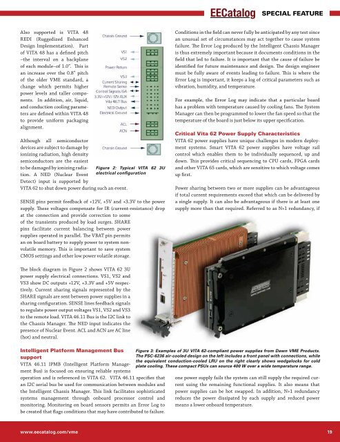
<strong>to</strong> be damaged by ionizing radia- Figure 2: Typical VITA 62 3U<br />
tion. A NED (Nuclear Event<br />
Detect) input is supported by<br />
electrical configuration<br />
VITA 62 <strong>to</strong> shut down power during such an event.<br />
SENSE pins permit feedback of +12V, +5V and +3.3V <strong>to</strong> <strong>the</strong> power<br />
supply. These voltages compensate for IR (current-resistance) drop<br />
at <strong>the</strong> connection and provide correction <strong>to</strong> some<br />
of <strong>the</strong> transients produced by load surges. SHARE<br />
pins facilitate current balancing between power<br />
supplies operated in parallel. The VBAT pin permits<br />
an on board battery <strong>to</strong> supply power <strong>to</strong> system nonvolatile<br />
memory. This is important <strong>to</strong> save system<br />
CMOS settings and o<strong>the</strong>r low power volatile s<strong>to</strong>rage.<br />
The block diagram in Figure 2 shows VITA 62 3U<br />
power supply electrical connections. VS1, VS2 and<br />
VS3 show DC outputs +12V, +3.3V and +5V respectively.<br />
Current sharing signals represented by <strong>the</strong><br />
SHARE signals are sent between power supplies in a<br />
sharing configuration. SENSE lines feedback signals<br />
<strong>to</strong> regulate power output voltages VS1, VS2 and VS3<br />
<strong>to</strong> <strong>the</strong> remote load. VITA 46.11 Bus is <strong>the</strong> I2C link <strong>to</strong><br />
<strong>the</strong> Chassis Manager. The NED input indicates <strong>the</strong><br />
presence of Nuclear Event. ACL and ACN are AC line<br />
(hot) and neutral.<br />
Intelligent Platform Management Bus<br />
support<br />
VITA 46.11 IPMB (Intelligent Platform Management<br />
Bus) is focused on ensuring reliable systems<br />
operation and is referenced in VITA 62. VITA 46.11 specifies that<br />
an I2C serial bus be used for communication between modules and<br />
<strong>the</strong> Intelligent Chassis Manager. This link facilitates sophisticated<br />
systems management through onboard processor control and<br />
moni<strong>to</strong>ring. Moni<strong>to</strong>ring on board sensors permits an Error Log <strong>to</strong><br />
be created that flags conditions that may have contributed <strong>to</strong> failure.<br />
SPECIAL FEATURE<br />
Conditions in <strong>the</strong> field can never fully be anticipated by any test since<br />
an unusual set of circumstances may act <strong>to</strong>ge<strong>the</strong>r <strong>to</strong> cause system<br />
failure. The Error Log produced by <strong>the</strong> Intelligent Chassis Manager<br />
is thus extremely important because it documents conditions in <strong>the</strong><br />
field that led <strong>to</strong> failure. It is important that <strong>the</strong> cause of failure be<br />
identified for future maintenance and design. The design engineer<br />
must be fully aware of events leading <strong>to</strong> failure. This is where <strong>the</strong><br />
Error Log is important, it keeps a log of critical parameters such as<br />
vibration, humidity, and temperature.<br />
For example, <strong>the</strong> Error Log may indicate that a particular board<br />
has a problem with temperature caused by cooling fans. The System<br />
Manager can <strong>the</strong>n be programmed <strong>to</strong> lower <strong>the</strong> fan speed so that <strong>the</strong><br />
temperature of <strong>the</strong> board is just below its upper specification.<br />
Critical Vita 62 Power Supply Characteristics<br />
VITA 62 power supplies have unique challenges in modern deployment<br />
systems. Smart VITA 62 power supplies have voltage rail<br />
control which enables <strong>the</strong>m <strong>to</strong> be individually sequenced, up and<br />
down. This provides critical sequencing <strong>to</strong> CPU cards, FPGA cards<br />
and o<strong>the</strong>r VITA 65 cards, which are sensitive <strong>to</strong> which voltage comes<br />
up first.<br />
Power sharing between two or more supplies can be advantageous<br />
if <strong>to</strong>tal current requirements exceed that which can be delivered by<br />
a single supply. It can also be advantageous if <strong>the</strong>re is at least one<br />
supply more than that required. Referred <strong>to</strong> as N+1 redundancy, if<br />
Figure 3: Examples of 3U VITA 62-compliant power supplies from Dawn <strong>VME</strong> Products.<br />
The PSC-6236 air-cooled design on <strong>the</strong> left includes a front panel with connections, while<br />
<strong>the</strong> equivalent conduction-cooled LRU on <strong>the</strong> right clearly shows wedgelocks for cold<br />
plate cooling. These compact PSUs can source 400 W over a wide temperature range.<br />
one power supply fails <strong>the</strong> system can still supply <strong>the</strong> required current<br />
using <strong>the</strong> remaining functional supplies. It also means that<br />
power supplies can be hot swapped. In addition, N+1 redundancy<br />
reduces <strong>the</strong> power dissipated by each supply and reduced power<br />
means a lower onboard temperature.<br />
www.eecatalog.com/vme 19