the Engineers' Guide to VME, VPX & VXS 2013 - Subscribe
the Engineers' Guide to VME, VPX & VXS 2013 - Subscribe
the Engineers' Guide to VME, VPX & VXS 2013 - Subscribe

You also want an ePaper? Increase the reach of your titles
YUMPU automatically turns print PDFs into web optimized ePapers that Google loves.
Tackling <strong>the</strong> Challenge of Building Smaller,<br />
Lighter, and More Efficient Componentbased<br />
Avionics with CFD<br />
Component <strong>the</strong>rmal issues have <strong>to</strong> be managed in order<br />
<strong>to</strong> maintain high reliability in military aircraft and<br />
avionics environments. The ratio and tradeoff of size,<br />
weight, and power (SWaP) is a crucial system design<br />
consideration in modern defense systems. As aircraft<br />
are fitted with an increasing amount of electronics and<br />
with more components, <strong>the</strong>y become heavier—and<br />
more weight can mean less time in <strong>the</strong> target zone. But<br />
<strong>the</strong>y also become hotter as size density increases. The<br />
<strong>the</strong>rmal behavior can also vary from component vendor<br />
<strong>to</strong> vendor but also over <strong>the</strong> component aging process.<br />
This is due <strong>to</strong> <strong>the</strong> degradation of <strong>the</strong> materials used in<br />
<strong>the</strong> component and <strong>the</strong> influence of <strong>the</strong>rmal management<br />
over <strong>the</strong> lifetime of <strong>the</strong> component.<br />
A good understanding of semiconduc<strong>to</strong>r components’<br />
<strong>the</strong>rmal behavior is important because it is crucial <strong>to</strong><br />
<strong>the</strong> optimum <strong>the</strong>rmal design for a low SWaP ratio. Insufficient<br />
understanding of a component can lead not only<br />
<strong>to</strong> an oversized cooling system but also <strong>to</strong> a bad choice<br />
of <strong>the</strong> selected components intended for <strong>the</strong> lifetime system use.<br />
Thermal Characterization of Semiconduc<strong>to</strong>r Components<br />
A good way <strong>to</strong> begin formal component characterization is <strong>to</strong> create<br />
a “smart” implementation of <strong>the</strong> static test version of <strong>the</strong> Joint Electron<br />
Devices Engineering Council (JEDEC) JESD51-1 electrical test<br />
method [1] that allows for continuous measurement during a heating<br />
or cooling transient.<br />
The characterization method uses <strong>the</strong> temperature sensitivity of<br />
<strong>the</strong> semiconduc<strong>to</strong>r component. This sensitivity has <strong>to</strong> be measured<br />
before <strong>the</strong> actual characterization can begin, and it should be done<br />
according <strong>to</strong> <strong>the</strong> JESD51-14 standard <strong>to</strong> record <strong>the</strong> cooling curve of<br />
<strong>the</strong> component.<br />
Once <strong>the</strong> measured temperature sensitivity parameters (TSP) are<br />
obtained, <strong>the</strong> component can be characterized by powering up <strong>the</strong><br />
device (heating it) with PH [Watt] until a steady state is reached.<br />
Once <strong>the</strong> junction temperature TJ is constant, <strong>the</strong> heating current<br />
is switched off <strong>to</strong> a lower measuring current that creates a low<br />
SPECIAL FEATURE<br />
Computational Fluid Dynamics software helps defense systems designers doubly:<br />
it aids in optimizing component SWaP, and models device <strong>the</strong>rmal behavior across<br />
time and vendors.<br />
By Boris Marovic, Product Marketing Manager,<br />
Men<strong>to</strong>r Graphics<br />
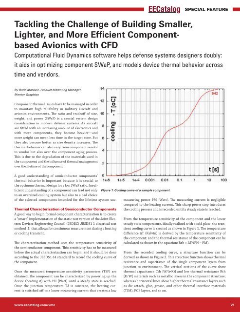
Figure 1: Cooling curve of a sample component.<br />
measuring power PM [Watt]. The measuring current is negligible<br />
compared <strong>to</strong> <strong>the</strong> heating current. This sharp power step introduces<br />
<strong>the</strong> cooling process and is recorded until a steady state is reached.<br />
From <strong>the</strong> temperature sensitivity of <strong>the</strong> component and <strong>the</strong> lower<br />
steady state temperature, ideally realized with a cold plate, <strong>the</strong> transient<br />
cooling curve is created as shown in Figure 1. The temperature<br />
difference ΔT (Kelvin) is derived by <strong>the</strong> temperature sensitivity of<br />
<strong>the</strong> component; and <strong>the</strong> <strong>the</strong>rmal resistance of <strong>the</strong> component can be<br />
calculated as shown in <strong>the</strong> equation: Rth = ΔT/(PH ‒ PM).<br />
From <strong>the</strong> recorded cooling curve, a structure function can be<br />
derived as shown in Figure 2. This structure function shows <strong>the</strong>rmal<br />
resistance and capacitance of <strong>the</strong> single component layers from<br />
junction <strong>to</strong> environment. The vertical sections of <strong>the</strong> curve show<br />
<br />
[K/W] materials such as metallic layers in <strong>the</strong> component structure;<br />
whereas horizontal lines show higher <strong>the</strong>rmal resistance layers such<br />
as die attach, glue, grease, and o<strong>the</strong>r <strong>the</strong>rmal interface materials<br />
(TIM), PCB layers, and so on.<br />
www.eecatalog.com/vme 21