the Engineers' Guide to VME, VPX & VXS 2013 - Subscribe
the Engineers' Guide to VME, VPX & VXS 2013 - Subscribe
the Engineers' Guide to VME, VPX & VXS 2013 - Subscribe

Create successful ePaper yourself
Turn your PDF publications into a flip-book with our unique Google optimized e-Paper software.
SPECIAL FEATURE<br />
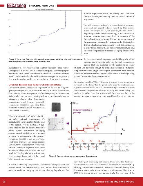
Figure 2: Structure function of a sample component showing <strong>the</strong>rmal capacitance<br />
(vertically) and <strong>the</strong>rmal resistance (horizontally)<br />
Each step of <strong>the</strong> structure function can <strong>the</strong>n be described as a resis<strong>to</strong>r<br />
and capaci<strong>to</strong>r in a Cauer ladder as shown in Figure 3. By specifying <strong>the</strong><br />
final node “case” of <strong>the</strong> component in <strong>the</strong> curve, a compact <strong>the</strong>rmal<br />
model can be derived and used for accurate component representation<br />
in a simulation for <strong>the</strong> <strong>the</strong>rmal resistance from junction <strong>to</strong> case.<br />
Lifetime Testing and Failure Characterization<br />
Component characterization is important <strong>to</strong> be able <strong>to</strong> judge <strong>the</strong><br />
quality of components for two reasons. Firstly, manufacturers should<br />
characterize components production by taking samples <strong>to</strong> determine<br />
if <strong>the</strong> production process is running without errors. Secondly, system<br />
integra<strong>to</strong>rs should also characterize<br />
components used because naturally<br />
component properties can vary from<br />
vendor <strong>to</strong> vendor and such variation can<br />
affect SWaP tradeoffs.<br />
With <strong>the</strong> necessity of high reliability<br />
for safety critical components, it’s<br />
important <strong>to</strong> ensure perfect functioning<br />
of <strong>the</strong> system over its lifetime. A system’s<br />
lifetime can be several thousand<br />
hours under constantly changing<br />
environmental conditions such as temperature<br />
variations and shocks, pressure<br />
variations, humidity, and so on. These<br />
conditions increase <strong>the</strong> aging process<br />
and can result in component or material<br />
failures. Material degrades over time<br />
because of <strong>the</strong>se fluctuations and can<br />
result in TIM degradation, die delamination,<br />
package hermeticity failure, and<br />
o<strong>the</strong>r undesirable behavior.<br />
When characterizing components, <strong>the</strong>y are usually exposed <strong>to</strong> harsh<br />
environments that are even worse than <strong>the</strong> actual environments in<br />
order <strong>to</strong> accelerate <strong>the</strong> aging process and identify degradation. This<br />
Figure 3: Step by step from component <strong>to</strong> Cauer ladder.<br />
is called highly accelerated life testing (HALT) and can<br />
shorten <strong>the</strong> original testing time by several orders of<br />
magnitude.<br />
Thermal characterization is a nondestructive measurement<br />
and can reveal failures caused by this process<br />
inside <strong>the</strong> component. If, for example, <strong>the</strong> die attach is<br />
degrading and <strong>the</strong> die delaminating, it will result in an<br />
increased <strong>the</strong>rmal resistance. Such an increase of <strong>the</strong><br />
<strong>the</strong>rmal resistance increases <strong>the</strong> junction temperature of<br />
<strong>the</strong> component because <strong>the</strong> heat cannot be dissipated as<br />
it is for a healthy component. As a result, <strong>the</strong> component<br />
is likely <strong>to</strong> fail sooner than a healthy component, as long<br />
excessive temperature increases <strong>the</strong> aging process even<br />
more.<br />
As <strong>the</strong> component changes and heat builds up, <strong>the</strong> failure<br />
process has begun. As well, <strong>the</strong> <strong>the</strong>rmal management<br />
system that was designed for <strong>the</strong> system is no longer<br />
efficient and powerful enough <strong>to</strong> cope with basically a “different”<br />
component than <strong>the</strong> originally designed component. If in addition<br />
<strong>the</strong> system has <strong>to</strong> function in a worse-case scenario of a failing cooling<br />
system, <strong>the</strong> situation becomes even worse.<br />
The Men<strong>to</strong>r Graphics T3Ster® <strong>the</strong>rmal transient tester uses a measurement<br />
methodology for <strong>the</strong> junction-<strong>to</strong>-case <strong>the</strong>rmal resistance<br />
of power semiconduc<strong>to</strong>r devices that makes it possible <strong>to</strong> <strong>the</strong>rmally<br />
characterize a component with high accuracy and repeatability. The<br />
result is far richer data that is measured from much earlier in <strong>the</strong><br />
junction temperature transient than possible with o<strong>the</strong>r techniques.<br />
The T3Ster post-processing software fully supports <strong>the</strong> JESD51-14<br />
standard for junction-<strong>to</strong>-case <strong>the</strong>rmal resistance measurement [2],<br />
allowing <strong>the</strong> temperature versus time curve obtained directly from<br />
<strong>the</strong> measurement <strong>to</strong> be re-cast as “structure functions” (described in<br />
JESD51-14 Annex A), and <strong>the</strong>n au<strong>to</strong>matically find <strong>the</strong> value of <strong>the</strong><br />
22 Engineers’ <strong>Guide</strong> <strong>to</strong> <strong>VME</strong>, <strong>VPX</strong> & <strong>VXS</strong> <strong>2013</strong>