Motor Protection MS 220 DA/ MCB 112 VLT® PTC ... - ziehl.de
Motor Protection MS 220 DA/ MCB 112 VLT® PTC ... - ziehl.de
Motor Protection MS 220 DA/ MCB 112 VLT® PTC ... - ziehl.de

Create successful ePaper yourself
Turn your PDF publications into a flip-book with our unique Google optimized e-Paper software.
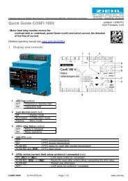
<strong>Motor</strong> <strong>Protection</strong> <strong>MS</strong> <strong>220</strong> <strong>DA</strong>/<br />
<strong>MCB</strong> <strong>112</strong> VLT ® <strong>PTC</strong> Thermistor Option<br />
The documentation for the <strong>MS</strong> <strong>220</strong> <strong>DA</strong>/ <strong>MCB</strong> <strong>112</strong> VLT ® <strong>PTC</strong> Thermistor Card contains two parts.<br />
The first part documents the basic functionality of the option and has been <strong>de</strong>veloped with ZIEHL industrie-elektronik to serve as the basis for the ATEX<br />
approval from PTB. The option is referred to as <strong>MS</strong> <strong>220</strong> <strong>DA</strong> in this part as this is the name selected by ZIEHL industre-elektronik and the name on the<br />
ATEX certificate.<br />
The second part follows the standard Danfoss Drives documentation structure and the option is referred to as <strong>MCB</strong> <strong>112</strong> VLT ® <strong>PTC</strong> Thermistor Card which<br />
is in line with the naming of the other options available. This part inclu<strong>de</strong>s the <strong>de</strong>dicated parameter setup for the advanced alarm handling of the <strong>MCB</strong><br />
<strong>112</strong>. Furthermore, this part inclu<strong>de</strong>s more elaborations regarding Safe Stop, consi<strong>de</strong>rations related to the drive and further safety precautions.<br />
It is strongly recommen<strong>de</strong>d to read both parts of the documentation.<br />
VLT ® is a registered Danfoss tra<strong>de</strong>mark 1 1
<strong>Motor</strong> <strong>Protection</strong> <strong>MS</strong> <strong>220</strong> <strong>DA</strong> Contents<br />
Contents<br />
1 Application and short <strong>de</strong>scription 3<br />
Application and Short Description 3<br />
Connection Plan 3<br />
Overview of Functions 3<br />
Block Diagram 4<br />
Detailed Description 4<br />
2 Important Notes 5<br />
Important Notes 5<br />
3 Assembly 7<br />
Assembly 7<br />
Putting into Operation 7<br />
Maintenance and Repair 7<br />
Warranty 7<br />
Safety Integrity Level (EN 61508) 7<br />
Troubleshooting 7<br />
4 Technical Data 9<br />
5 Safety Instructions and References 11<br />
Special Remarks for Explosive Gas Atmosphere Areas (Zone 1 and Zone 2)<br />
Special Remarks for Use in the Presence of Combustible Dust (Zone 21 and Zone<br />
11<br />
22) 11<br />
Wiring 11<br />
Resistance and Length of Sensor Circuit Lines 11<br />
Safe Separation 12<br />
Stop Function, Stop Category 0 12<br />
Start and Restart 12<br />
Manual Resetting 12<br />
Additional Notes for the SIL Category According EN 61508 12<br />
Maintenance and Repair 12<br />
6 Install the <strong>MS</strong> <strong>220</strong> <strong>DA</strong> Option in the Frequency Converter 13<br />
7 Certificates 15<br />
MG33V102 - VLT ® is a regisered Danfoss tra<strong>de</strong>mark 1
1<br />
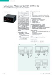
1 Application and short <strong>de</strong>scription <strong>Motor</strong> <strong>Protection</strong> <strong>MS</strong> <strong>220</strong> <strong>DA</strong><br />
2 MG33V102 - VLT ® is a regisered Danfoss tra<strong>de</strong>mark
<strong>Motor</strong> <strong>Protection</strong> <strong>MS</strong> <strong>220</strong> <strong>DA</strong> 1 Application and short <strong>de</strong>scription<br />
1 Application and short <strong>de</strong>scription<br />
1.1 Application and Short Description<br />
TMP tripping <strong>de</strong>vice <strong>MS</strong> <strong>220</strong> <strong>DA</strong> - <strong>MCB</strong> <strong>112</strong> <strong>PTC</strong> Thermistor Option B is <strong>de</strong>signed as a passive option interface for Danfoss Frequency Converter series<br />
VLT ® . The <strong>MS</strong> <strong>220</strong> <strong>DA</strong> fulfils the requirements of the document P400 Platform I<strong>de</strong>ntification of passive option and will be recognized automatically by<br />
the drive.<br />
TMP tripping <strong>de</strong>vice is according EN 60947-8 (VDE 0660 part 0302). <strong>PTC</strong>-thermistor sensors according DIN 44081 and 44082 (VDE 0660 part 0303) can<br />
be connected. The TMP tripping <strong>de</strong>vice can be used to protect electrical machines against inadmissible heating due to overload. With ATEX marking it<br />
can also be used as protection <strong>de</strong>vice for explosion-protected motors in areas with explosive gas atmospheres Zone 1 (refer to marking G) and locations<br />
with explosive dust atmospheres Zone 21 (refer to marking D). All functions in the TMP tripping <strong>de</strong>vice serve to protect non-explosive-protected motors<br />
and explosive-protected motors in regular operation and in case of failure.<br />
Approvals: marking see type plate on the <strong>de</strong>vice.<br />
1.2 Connection Plan<br />
1.3 Overview of Functions<br />
The TMP tripping <strong>de</strong>vice <strong>MS</strong> <strong>220</strong> <strong>DA</strong> - <strong>MCB</strong> <strong>112</strong> <strong>PTC</strong> Thermistor Option B inclu<strong>de</strong>s a tripping stage for <strong>PTC</strong>-thermistor sensors with save potential separation<br />
from supply voltage and ground. The tripping function switches off the +24 V DC-voltage directly at the Safety Stop T37 of the drive. The PNP logic<br />
output terminal X44/10 signals the status in case of failure. The TMP tripping <strong>de</strong>vice works according to the closed-circuit principle. The <strong>de</strong>vice trips in<br />
case of short-circuit or line interruption.<br />
The <strong>MS</strong> <strong>220</strong> <strong>DA</strong> needs +24 VDC supply voltage. The serial EEPROM enables the drive to recognize the built-in option module.<br />
MG33V102 - VLT ® is a regisered Danfoss tra<strong>de</strong>mark 3<br />
1
1<br />
1 Application and short <strong>de</strong>scription <strong>Motor</strong> <strong>Protection</strong> <strong>MS</strong> <strong>220</strong> <strong>DA</strong><br />
1.4 Block Diagram<br />
1.5 Detailed Description<br />
A current monitors continuously the resistance of the sensors. In cold state, the resistance is < 250 Ω per sensor (sensor circuit < 1.5 kΩ). The output<br />
to X44/12 is high = 1. The resistance of the sensor rises rapidly at nominal response temperature TNF. At a resistance of 3…4 kΩ output to X44/12<br />
changes to low = 0. The <strong>de</strong>vices also switches off in the case of sensor or line short-circuit 1) (< 20 Ω) or sensor or line interruption. It switches on<br />
automatically when the temperature has <strong>de</strong>creased approx. 5 °C.<br />
Attention ! 2) : trip status is not stored and not non-volatile.<br />
Depending on the number of sensors the following tripping and release<br />
temperatures will be achieved with respect of TNF (nominal response<br />
temperature of the sensors):<br />
Trip temperature Release temperature<br />
3 sensors in series TNF + 5 K TNF – 5 K<br />
6 sensors in series TNF TNF – 20 K<br />
4 MG33V102 - VLT ® is a regisered Danfoss tra<strong>de</strong>mark
<strong>Motor</strong> <strong>Protection</strong> <strong>MS</strong> <strong>220</strong> <strong>DA</strong> 2 Important Notes<br />
2 Important Notes<br />
2.1 Important Notes<br />
To use the equipment flawless and safely, transport and store properly, install and start professionally and operate as directed.<br />
Only let persons work with the equipment who are familiar with installation, start and use and who have appropriate qualification corresponding to their<br />
function. They must observe the contents of the instructions manual, the information written on the equipment and the relevant security instructions for<br />
the setting up and the use of electrical units.<br />
The equipments are built according to EN 60947 and checked and leave the plant according to safety in perfect condition. To keep this condition, observe<br />
the safety instructions with the headline Attention written in the instructions manual. Ignoring of the safety instructions may lead to <strong>de</strong>ath, physical injury<br />
or damage of the equipment itself and of other apparatus and equipment.<br />
If, in any case the information in the instructions manual is not sufficient, please contact our company or the responsible representative.<br />
Instead of the industrial norms and regulations written in this instructions manual valid for Europe, you must observe out of their geographical scope the<br />
valid and relevant regulations of the corresponding country.<br />
Attention! Safety Circuits according to EN 60204. The equipment must not be used alone for functions, when an automatic start must<br />
be avoi<strong>de</strong>d.<br />
MG33V102 - VLT ® is a regisered Danfoss tra<strong>de</strong>mark 5<br />
2
3<br />
3 Assembly <strong>Motor</strong> <strong>Protection</strong> <strong>MS</strong> <strong>220</strong> <strong>DA</strong><br />
6 MG33V102 - VLT ® is a regisered Danfoss tra<strong>de</strong>mark
<strong>Motor</strong> <strong>Protection</strong> <strong>MS</strong> <strong>220</strong> <strong>DA</strong> 3 Assembly<br />
3Assembly<br />
3.1 Assembly<br />
The TMP tripping <strong>de</strong>vice <strong>MS</strong> <strong>220</strong> <strong>DA</strong> - <strong>MCB</strong> <strong>220</strong> <strong>PTC</strong> Thermistor Option B is inten<strong>de</strong>d to be used in Danfoss Automation Drives series VLT ® . <strong>PTC</strong>-thermistor<br />
sensors are connected directly to the terminals T1, T2. The lines of Safe Stop T37 and Logic Out are to be routed separately.<br />
Attention: Routed lines must keep enough distance to sensor lines and other mainstream lines.<br />
3.2 Putting into Operation<br />
After installation and before first operation, the correct function of the TMP tripping <strong>de</strong>vice has to be tested by simulation of the sensor resistance at<br />
terminals T1, T2.<br />
This test must also be done after modifications in the installation.<br />
This test can additionally be done with maintenance services:<br />
Short circuit test: resistance 20 Ω in parallel to sensor terminals T1, T2<br />
Line interruption test: disconnect sensor line at terminal T1 or T2<br />
Temperature test: increase resistance 50…1500 Ω up to 4000 Ω<br />
The tripping function will be displayed on the drive display and must be reseted manually.<br />
Please notice the admissible ambient conditions > Technical data.<br />
Atteention! The TMP tripping <strong>de</strong>vice <strong>MS</strong> <strong>220</strong> <strong>DA</strong> was <strong>de</strong>signed for Class A. The use of this product in home applications can cause radio<br />
frequency distortions.<br />
3.3 Maintenance and Repair<br />
The <strong>de</strong>vices are maintenance-free. Only the manufacturer may accomplish repairs. We recommend an examination within the regular maintenance periods<br />
of the plant, in which the equipment is installed.<br />
3.4 Warranty<br />
The guarantee presupposes the observance of this Operating Instruction (safety and start-up instructions).<br />
3.5 Safety Integrity Level (EN 61508)<br />
The safety function of the safety equipment<br />
• achieves SIL 1 within a proof test interval of 3 years<br />
• achieves SIL 2 within a proof test interval of 2 years.<br />
The safety function fulfils the recommendations of category 2 according ISO 13849-1:1999 (EN 954-1:1996). More safety-related parameters -> Technical<br />
data<br />
3.6 Troubleshooting<br />
• The resistance within the sensor circuit must have a value 50 Ω < R < 1500 Ω. The voltage at terminals T1, T2 must be < 2.5 VDC when <strong>PTC</strong>thermistor<br />
sensors are connected and the temperature is below TNF.<br />
• The TMP tripping <strong>de</strong>vice must shut down when the sensor circuit is open. The voltage at terminals T1, T2 must be < 9 VDC.<br />
MG33V102 - VLT ® is a regisered Danfoss tra<strong>de</strong>mark 7<br />
3
4<br />
4 Technical Data <strong>Motor</strong> <strong>Protection</strong> <strong>MS</strong> <strong>220</strong> <strong>DA</strong><br />
8 MG33V102 - VLT ® is a regisered Danfoss tra<strong>de</strong>mark
<strong>Motor</strong> <strong>Protection</strong> <strong>MS</strong> <strong>220</strong> <strong>DA</strong> 4 Technical Data<br />
4 Technical Data<br />
4.1 Technical Data<br />
Power supply<br />
Rated supply voltage Us DC 24 V<br />
Tolerance voltage Us DC 21…28 V<br />
Power consumption < 1 W<br />
<strong>PTC</strong>-thermistor connection X44/1+X44/2<br />
Standard DIN 44081 / DIN 44082<br />
Numbers set with 3 - 6 <strong>PTC</strong>s in series<br />
Cut-out-point 3.3 kΩ…3.65 kΩ…3.85 kΩ<br />
Reclosing point 1.7 kΩ…1.8 kΩ …1.95 kΩ<br />
Collective resistance cold sensors ≤1.65 kΩ<br />
Terminal voltage (sensors) ≤ 2.5 V at R ≤ 3.65 kΩ, ≤ 9 V at R = ∞<br />
Terminal current (sensors) < 1 mA<br />
Short circuit 20 Ω ≤ R ≤ 40 Ω<br />
Power consumption < 2 mW<br />
Safety Stop X44/12<br />
- PNP Transistor output<br />
Logic voltage level 0…24 VDC<br />
Low = 0, PNP < 4 VDC<br />
Voltage<br />
High = 1, PNP > 20 VDC<br />
Current 60 mA<br />
Safety Stop X44/10<br />
- PNP logic output<br />
Logic voltage level 0…24 VDC<br />
Low = 0, PNP < 5 VDC<br />
Voltage<br />
High = 1, PNP > 10 VDC<br />
Current 10 mA<br />
Testing conditions<br />
Standard EN 60 947-8, EN 50178<br />
Rated impulse voltage 6000 V<br />
Over voltage category III<br />
Contamination level 2<br />
Rated insulation voltage Ui 690 V<br />
Safe separation up to Ui 500 V<br />
-20 - +60 °C<br />
Rated ambient temperature range<br />
EN 60068-2-2 Dry Heat<br />
Rel. humidity 5…95 % without con<strong>de</strong>nsation<br />
EMC – Immunity industry standard EN 61000-6-2<br />
EMC – Emission industry standard EN 61000-6-4<br />
Vibration resistance 10…10000 Hz 1.14 g<br />
Shock resistance 50 g<br />
Safety-related parameters<br />
ISO 13849-1 Cat. 2<br />
SIL 1 within a proof test interval of 3 years<br />
EN 61508<br />
SIL 2 within a proof test interval of 2 years<br />
HFT Proof test interval PFDav SFF λS + λDD λDU<br />
0 1 year 4.10 x 10 -3 90 % 8515 FIT 932 FIT<br />
MG33V102 - VLT ® is a regisered Danfoss tra<strong>de</strong>mark 9<br />
4
4<br />
4 Technical Data <strong>Motor</strong> <strong>Protection</strong> <strong>MS</strong> <strong>220</strong> <strong>DA</strong><br />
Housing<br />
- Form 130B4065<br />
Dimensions (H x W x D) mm 82.5 x 69.5 x 29.5<br />
Line connection solid wire<br />
1 x 0.5 - 1.5 mm 2<br />
(AWG 20…AWG 16 solid wire)<br />
<strong>Protection</strong> class EN 60529 IP 20<br />
Weight approx. 50 g<br />
10 MG33V102 - VLT ® is a regisered Danfoss tra<strong>de</strong>mark
<strong>Motor</strong> <strong>Protection</strong> <strong>MS</strong> <strong>220</strong> <strong>DA</strong> 5 Safety Instructions and References<br />
5 Safety Instructions and References<br />
Safety Instructions and references for putting into operation– please read carefully!<br />
5.2 Special Remarks for Explosive Gas Atmosphere Areas (Zone 1 and<br />
Zone 2)<br />
The increased danger within hazardous areas requires the careful attention of the safety instructions and references for putting into operation. Observe<br />
the national safety rules and regulations for prevention of acci<strong>de</strong>nts as well as the European Standard EN 60079-14 Electrical apparatus for explosive gas<br />
atmospheres - Part 14: Electrical installations in hazardous areas (other than mines). Installation, electrical connection and commissioning to be carried<br />
out by trained service personnel only. Inappropriate behaviour can cause heavy personal damage and damages to property.<br />
The response of the thermal motor protection must directly switch off the motor, also when used together with converters. This must be realized in the<br />
logic section or configuration in the converter.<br />
The relay may be installed only outsi<strong>de</strong> potentially explosive atmospheres for the protection of explosive-protected motors. Within potentially explosive<br />
atmospheres the equipment is to be provi<strong>de</strong>d with a pressurized enclosure according EN 60079-2.<br />
5.3 Special Remarks for Use in the Presence of Combustible Dust (Zone<br />
21 and Zone 22)<br />
The increased danger within hazardous areas of combustible dust requires the careful attention of the safety instructions and references for putting into<br />
operation. Observe the national safety rules and regulations for prevention of acci<strong>de</strong>nts as well as the European Standard EN 50281-1-2 Electrical apparatus<br />
for use in the presence of combustible dust. Installation, electrical connection and commissioning to be carried out by qualified service personnel<br />
only. Inappropriate behaviour can cause heavy personal damage and damages to property.<br />
The relay may be installed only outsi<strong>de</strong> potentially explosive atmospheres for the protection of explosive-protected motors. Within potentially explosive<br />
atmospheres the equipment is to be provi<strong>de</strong>d with a dust proofed enclosure according to EN 60529.<br />
5.4 Wiring<br />
The lines of the sensor circuit are to be routed as separate control lines. The use of lines of the supply cable or other mainstream lines is not permissible.<br />
If extreme inductive or capacitive stray effects are to be expected by parallel cables of the power installation, shiel<strong>de</strong>d control lines should be used.<br />
5.5 Resistance and Length of Sensor Circuit Lines<br />
The line resistance within the sensor circuit may not exceed a value of 20 Ω. Maximum of permissible length for sensor circuit lines:<br />
Wire cross section Wire length<br />
1.5 mm2 2 x 150 m<br />
1.0 mm2 2 x 100 m<br />
0.75 mm2 2 x 50 m<br />
0.5 mm2 2 x 50 m<br />
With commissioning and after modification of the plant the sensor resistance must be checked with a suitable measuring instrument. With a resistance<br />
< 50 Ω the sensor circuit is to be examined for short-circuit.<br />
MG33V102 - VLT ® is a regisered Danfoss tra<strong>de</strong>mark 11<br />
5
5<br />
5 Safety Instructions and References <strong>Motor</strong> <strong>Protection</strong> <strong>MS</strong> <strong>220</strong> <strong>DA</strong><br />
Check <strong>PTC</strong>s only with measuring voltages of < 2.5 V.<br />
5.6 Safe Separation<br />
<strong>PTC</strong>-thermistor circuit (T1, T2) has a safe separation to low-voltage electric circuits PELV (T37, Logic Out and Interface). -> Technical data.<br />
5.7 Stop Function, Stop Category 0<br />
A stop function released by the protection <strong>de</strong>vice must transfer the machine after manipulation of this function as fast as possible into a safe condition.<br />
The stop function must have top priority.<br />
In case of failure the <strong>MS</strong> <strong>220</strong> <strong>DA</strong> motor protection causes a stop command at the Safe Stop T37 and the drive directly stop the engine.<br />
5.8 Start and Restart<br />
A restart may take place automatically only if no dangerous condition can be present.<br />
The <strong>MS</strong> <strong>220</strong> <strong>DA</strong> motor protection switches on automatically when the engine has cooled down. If automatically restart is programmed additional measures<br />
are required to prevent a restart of the engine in case of risk of a dangerous situation.<br />
5.9 Manual Resetting<br />
After introducing a stop by the protection <strong>de</strong>vice this must be maintained, until the manual resetting mechanism is operated and safe conditions for a<br />
restart are given. The manual resetting may only be possible, if all safety functions and protection <strong>de</strong>vices are effective.<br />
5.10 Additional Notes for the SIL Category According EN 61508<br />
The safety function must be tested within regular intervals. It is recommen<strong>de</strong>d to test once annually or within the maintenance cycle of the plant. For<br />
recurring examinations of electrical systems in hazardous areas the inspection period must be kept within 3 years. One fault is recognized by the safety<br />
test. One fault between safety tests can cause the loss of protection.<br />
The following must be tested additionally to recurring examinations with maintenance services:<br />
Short circuit test: resistance 20 Ω in parallel to sensor terminals T1, T2<br />
Line interruption test: disconnect sensor line at terminal T1 or T2<br />
Temperature test: increase resistance 50…1500 Ω to 4000 Ω<br />
The tripping function will be stated at the drive display and can be manually reset when the failure is removed. If an error is <strong>de</strong>tected no restart must be<br />
induced until the error is cleared.<br />
5.11 Maintenance and Repair<br />
The <strong>de</strong>vice is maintenance-free. Only the manufacturer may accomplish repairs. EN 60079-17 and/or EN 50281-1-2 are to be observed.<br />
12 MG33V102 - VLT ® is a regisered Danfoss tra<strong>de</strong>mark
<strong>Motor</strong> <strong>Protection</strong> <strong>MS</strong> <strong>220</strong> <strong>DA</strong><br />
6 Install the <strong>MS</strong> <strong>220</strong> <strong>DA</strong> Option in the Frequency Converter<br />
Before start, disconnect the supply voltage to the frequency converter! Do never install an option card into the frequency converter<br />
while in operation!<br />
The <strong>MS</strong> <strong>220</strong> <strong>DA</strong> option is exclusively inten<strong>de</strong>d for use in option slot „B“.<br />
- Remove LCP control unit, terminal cover and standard frame (see Photo 1 or 2).<br />
Illustration 6.1: Photo 1 Illustration 6.2: Photo 2<br />
- If necessary, wire the terminal block with terminal 39 - 55 first.<br />
- Insert the <strong>MS</strong> <strong>220</strong> <strong>DA</strong> option into slot „B“. (see Photo 3)<br />
Illustration 6.3: Photo 3 Illustration 6.4: Photo 4<br />
6 Install the <strong>MS</strong> <strong>220</strong> <strong>DA</strong> Option in the Frequency<br />
Converter<br />
MG33V102 - VLT ® is a regisered Danfoss tra<strong>de</strong>mark 13<br />
6
6<br />
6 Install the <strong>MS</strong> <strong>220</strong> <strong>DA</strong> Option in the Frequency<br />
Converter <strong>Motor</strong> <strong>Protection</strong> <strong>MS</strong> <strong>220</strong> <strong>DA</strong><br />
- The plastic cover must point downwards.<br />
- Connect the motor resistor (thermistor) to terminals T1 and T2 of the <strong>MS</strong> <strong>220</strong> <strong>DA</strong>. Open jumper 12-37 on the frequency converter and connect<br />
terminal X44/12 on the <strong>MS</strong> <strong>220</strong> <strong>DA</strong> with terminal 37 (Safe Stop) on the frequency converter (see Photo 4). Only then can the VLT AutomationDrive<br />
FC 302 be safely shut down in the case of malfunction. The output on terminal X44/12 of the <strong>MS</strong> <strong>220</strong> <strong>DA</strong> must always be wired into the chain<br />
on the Safe Stop input on terminal 37 on the frequency converter in or<strong>de</strong>r to ensure shutdown of power in case of malfunction.<br />
- Continue the necessary wiring of the <strong>MS</strong> <strong>220</strong> <strong>DA</strong>. See connection diagram in section 1.2.<br />
- Afterwards, remove the gaps for slot „B“ from the <strong>de</strong>eper frame supplied, and reinsert the frame, terminal cover, and the LCP control unit. (see<br />
Photos 5 or 6)<br />
Illustration 6.5: Photo 5 Illustration 6.6: Photo 6<br />
- Close the <strong>de</strong>vice with the cover or with the enclosure cover in or<strong>de</strong>r to restore the enclosure to its initial condition.<br />
- Restore the supply voltage to the frequency converter.<br />
Attention! Depending on the programmed parameters, the motor may start after the supply voltage is restored!<br />
- Configure new additional functions in the corresponding parameters.<br />
Attention! The operator or electrical installer is responsible for proper earthing and adherence to all applicable national and local safety<br />
regulations!<br />
14 MG33V102 - VLT ® is a regisered Danfoss tra<strong>de</strong>mark
<strong>Motor</strong> <strong>Protection</strong> <strong>MS</strong> <strong>220</strong> <strong>DA</strong> 7 Certificates<br />
7 Certificates<br />
MG33V102 - VLT ® is a regisered Danfoss tra<strong>de</strong>mark 15<br />
7
7<br />
7 Certificates <strong>Motor</strong> <strong>Protection</strong> <strong>MS</strong> <strong>220</strong> <strong>DA</strong><br />
16 MG33V102 - VLT ® is a regisered Danfoss tra<strong>de</strong>mark
<strong>Motor</strong> <strong>Protection</strong> <strong>MS</strong> <strong>220</strong> <strong>DA</strong> 7 Certificates<br />
MG33V102 - VLT ® is a regisered Danfoss tra<strong>de</strong>mark 17<br />
7
7<br />
7 Certificates <strong>Motor</strong> <strong>Protection</strong> <strong>MS</strong> <strong>220</strong> <strong>DA</strong><br />
18 MG33V102 - VLT ® is a regisered Danfoss tra<strong>de</strong>mark
130R0104 MG33V102<br />
www.danfoss.<strong>de</strong>/vlt<br />
Danfoss GmbH<br />
VLT Antriebstechnik<br />
Carl-Legien-Straße 8<br />
D-63073 Offenbach/Main<br />
Telefon: (069) 89 02-0<br />
Telefax: (069) 89 02-106<br />
www.danfoss.<strong>de</strong>/vlt<br />
*MG33V102*<br />
Rev. 11/2008
Operating Instructions<br />
<strong>MCB</strong> <strong>112</strong> <strong>PTC</strong> Thermistor Card<br />
for integration with the<br />
<strong>VLT®</strong> AutomationDrive FC 302
<strong>MCB</strong> <strong>112</strong> VLT ® <strong>PTC</strong> Thermistor Option Contents<br />
Contents<br />
1 How to Read these Operating Instructions 3<br />
Available Literature for VLT AutomationDrive FC 300 3<br />
Approvals 4<br />
Symbols 4<br />
Abbreviations 4<br />
Special Abbreviation 5<br />
2 Safety and Conformity 7<br />
Important Notes 7<br />
3 Introduction to <strong>MCB</strong> <strong>112</strong> VLT <strong>PTC</strong> Thermistor Card 9<br />
Introduction to <strong>MCB</strong> <strong>112</strong> <strong>PTC</strong> Thermistor Card 9<br />
VLT AutomationDrive Terminals 9<br />
Connection Schematic 10<br />
Overview of Functions 11<br />
4 How to Install 13<br />
Particular Instructions for EN 61508, Category SIL 1 and 2 13<br />
Installation of Option in the Frequency Converter 13<br />
Installation of a Category 0 Stop 14<br />
Startup 15<br />
5 Parameter Setup 17<br />
Alarm Handling 17<br />
Safe Stop Functionality 17<br />
6 Application Example 19<br />
<strong>MCB</strong> <strong>112</strong> <strong>PTC</strong> Termistor Card 19<br />
7 Troubleshooting 21<br />
Alarm/Warning Co<strong>de</strong> List 21<br />
Description of Alarm Word, Warning Word and Exten<strong>de</strong>d Status Word 21<br />
MG.33.V2.02 - VLT ® is a registered Danfoss tra<strong>de</strong>mark 1
1<br />
1 How to Read these Operating Instructions <strong>MCB</strong> <strong>112</strong> VLT ® <strong>PTC</strong> Thermistor Option<br />
2 MG.33.V2.02 - VLT ® is a registered Danfoss tra<strong>de</strong>mark
<strong>MCB</strong> <strong>112</strong> VLT ® <strong>PTC</strong> Thermistor Option 1 How to Read these Operating Instructions<br />
1 How to Read these Operating Instructions<br />
1.1.1 How to Read these Operating Instructions<br />
These Operating Instructions will help you get started, install, program, and troubleshoot your <strong>MCB</strong> <strong>112</strong> VLT ® <strong>PTC</strong> Thermistor Card option. Please read<br />
these operating instructions in full and, in or<strong>de</strong>r to be able to work with the system safely and professionally, particularly observe the hints and cautionary<br />
remarks.<br />
Chapter 1, How to Read these Operating Instructions, introduces the manual and informs you about the approvals, symbols, and abbreviations<br />
used in this literature.<br />
Chapter 2, Safety and Conformity, contains safety instructions and certificates for the <strong>MCB</strong> <strong>112</strong> VLT <strong>PTC</strong> Thermistor Card option and the VLT AutomationDrive<br />
FC 302.<br />
Chapter 3, Introduction to the <strong>MCB</strong> <strong>112</strong> VLT <strong>PTC</strong> Thermistor Card, informs you about the general aspects of the option and its functions. It also<br />
contains the technical data about the <strong>MCB</strong> <strong>112</strong> VLT <strong>PTC</strong> Thermistor Card.<br />
Chapter 4, How to Install, gui<strong>de</strong>s you through mechanical and technical installation.<br />
Chapter 5, Parameter setup, shows you the parameter settings associated with the <strong>MCB</strong> <strong>112</strong> VLT <strong>PTC</strong> Thermistor Card option.<br />
Chapter 6, Application Example, shows two examples of how the MBC <strong>112</strong> VLT <strong>PTC</strong> Thermistor Card can be used.<br />
Chapter 7, Troubleshooting, assists you in solving problems that may occur when using the <strong>MCB</strong> <strong>112</strong> VLT <strong>PTC</strong> Thermistor Card.<br />
1.1.2 Available Literature for VLT AutomationDrive FC 300<br />
- The VLT ® AutomationDrive FC 300 Operating Instructions provi<strong>de</strong> the neccessary information for getting the drive up and running.<br />
- The VLT ® AutomationDrive FC 300 Design Gui<strong>de</strong> entails all technical information about the drive <strong>de</strong>sign and applications including enco<strong>de</strong>r,<br />
resolver and relay options.<br />
- The VLT ® AutomationDrive FC 300 Programming Gui<strong>de</strong> contains information on how to programme the VLT AutomationDrive. Furthermore, you<br />
will find <strong>de</strong>scriptions of the parameters and parameter lists, which give an overview of the parameters in each group.<br />
- The VLT ® AutomationDrive FC 300 Profibus Operating Instructions provi<strong>de</strong> the information required for controlling, monitoring and programming<br />
the drive via a Profibus fieldbus.<br />
- The VLT ® AutomationDrive FC 300 DeviceNet Operating Instructions provi<strong>de</strong> the information required for controlling, monitoring and programming<br />
the drive via a DeviceNet fieldbus.<br />
- The VLT ® AutomationDrive FC 300 MCT 10 Operating Instructions provi<strong>de</strong> information for installation and use of the software on a PC.<br />
- The VLT ® AutomationDrive FC 300 IP21 / Type 1 Instruction provi<strong>de</strong>s information for installing the IP21 / Type 1 option.<br />
- The VLT ® AutomationDrive FC 300 24 V DC Backup Instruction provi<strong>de</strong>s information for installing the 24 V DC Backup option.<br />
Danfoss Drives technical literature is also available online at www.danfoss.com/drives.<br />
MG.33.V2.02 - VLT ® is a registered Danfoss tra<strong>de</strong>mark 3<br />
1
1<br />
1 How to Read these Operating Instructions <strong>MCB</strong> <strong>112</strong> VLT ® <strong>PTC</strong> Thermistor Option<br />
1.1.3 Approvals<br />
1.1.4 Symbols<br />
Symbols used in this Operating Instructions.<br />
NB!<br />
Indicates something to be noted by the rea<strong>de</strong>r.<br />
Indicates a general warning.<br />
1.1.5 Abbreviations<br />
Indicates a high-voltage warning.<br />
∗ Indicates <strong>de</strong>fault setting<br />
Alternating current AC<br />
American wire gauge AWG<br />
Ampere/AMP A<br />
Degrees Celsius °C<br />
Direct current DC<br />
Electro Magnetic Compatibility EMC<br />
Electronic Thermal Relay ETR<br />
Drive FC<br />
Gram g<br />
Hertz Hz<br />
Kilohertz kHz<br />
Local Control Panel LCP<br />
Meter m<br />
Millihenry Inductance mH<br />
Milliampere mA<br />
Millisecond ms<br />
Minute min<br />
Nanofarad nF<br />
Newton Meters Nm<br />
Parameter par.<br />
Protective Extra Low Voltage PELV<br />
Second s<br />
Volts V<br />
4 MG.33.V2.02 - VLT ® is a registered Danfoss tra<strong>de</strong>mark
<strong>MCB</strong> <strong>112</strong> VLT ® <strong>PTC</strong> Thermistor Option 1 How to Read these Operating Instructions<br />
1.1.6 Special Abbreviation<br />
Short Unit Value Description<br />
λs + λDD FIT 8515 (λDD): Dangerous failure rate <strong>de</strong>tected by diagnostics. Meaning: These failures could cause a dangerous state on the<br />
λDU FIT 932<br />
machine, but are <strong>de</strong>tected and reacted upon safely. (λs): Safe failure rate. Meaning: These failures do not cause a dangerous<br />
state on the machine.<br />
(λDU): Rate of dangerous failures not <strong>de</strong>tected by diagnostics. Meaning: These failures cause a dangerous state on the<br />
machine.<br />
HFT 0 Hardware Fault Tolerance (HFT): HFT = n means, that n+1 faults could cause a loss of the safety function. Example:<br />
HFT=1 means, the required function is still performed in the presence of 1 arbitrary fault of the safety <strong>de</strong>vice.<br />
PFD 4.1e-3 The Probability of Failure of Demand (PFD) specifies the average probability of a failure to perform the safety function on<br />
<strong>de</strong>mand. In the low <strong>de</strong>mand mo<strong>de</strong> the frequency of <strong>de</strong>mands for operation ma<strong>de</strong> on a safety related system is not greater<br />
than one per year and no greater than twice the proof-test frequency. The PFD, equivalent to the unavailability of a system<br />
at the time of a process <strong>de</strong>mand. Calculated on the basis of an FME<strong>DA</strong>. Calculated for test interval one year<br />
oo Abbreviation for ”out of”<br />
PFH h-1 λDU The Probability of dangerous failure per hour (PFH) specifies the failure rate (e.g. per hour) to perform the safety function<br />
continuously. This value shall be consi<strong>de</strong>red if the safety <strong>de</strong>vice is operated in high <strong>de</strong>mand (more often than once per<br />
year) or continuous mo<strong>de</strong> of operation, where the frequency of <strong>de</strong>mands for operation ma<strong>de</strong> on a safety-related system<br />
is greater than one per year or greater than twice the proof-test frequency. The PFH, may approximately be calculated<br />
to PFD/8760h un<strong>de</strong>r the assumption that the safety function is nee<strong>de</strong>d less than once per year and a diagnostic test is<br />
performed more than once per year. If the safety function is used more than once per year, or continuously, then PFH is<br />
equal to λDU for a 1oo1D system.<br />
SFF % 90 Safe Failure Fraction (SFF): Percentage part of safe failures and dangerous <strong>de</strong>tected failures of a safety function or a<br />
subsystem related to all failures.<br />
SIL 1-4 2 Safety Integrity Level (SIL) is <strong>de</strong>fined as a relative level of risk-reduction provi<strong>de</strong>d by a safety function, or to specify a<br />
target level of risk reduction. Four SIL levels are <strong>de</strong>fined, with SIL4 being the most <strong>de</strong>pendable and SIL1 being the least.<br />
A SIL is <strong>de</strong>termined based on a number of quantitative factors in combination with qualitative factors such as <strong>de</strong>velopment<br />
process and safety life cycle management. The requirements for a given SIL are not consistent among all of the functional<br />
safety standards.<br />
FIT 1E-9/<br />
hour<br />
Failure In Time: 1E-9 failures/hour<br />
SIL2 One of the four safety integrity levels <strong>de</strong>fined by IEC 61508. See also table below.<br />
ISO<br />
Cat 2. The standard ISO 13849 <strong>de</strong>als with “shutdown” systems, which perform a shut-down of the hazardous motion to achieve<br />
13849<br />
a safe state when a fault occurs. For this reason, what are termed “<strong>de</strong>signated architectures” have been created, in<br />
accordance to the categories B, 1, 2, 3, and 4. In the case of categories B and 1, the architectures are i<strong>de</strong>ntical, but the<br />
requirements of the safety principles differ; the same applies to categories 3 and 4. Here, the requirements for fault<br />
<strong>de</strong>tection, in particular, differ. The categories are mainly characterised by the structure. So the first parameter that has<br />
to be evaluated is the fault-tolerance. If the control system is tolerant to any single fault, category 3 or 4 can be claimed.<br />
In the other case, only category B, 1 or 2 is possible.<br />
FME<strong>DA</strong> Failure Mo<strong>de</strong>s, Effects, and Diagnostic Analysis<br />
1oo1D<br />
system<br />
The architecture consists of a single channel for the safety function (HFT=0)<br />
λS Safe failure rate (per hour)<br />
λSU Safe un<strong>de</strong>tectable failures<br />
λSD Safe <strong>de</strong>tectable failures<br />
λDU Un<strong>de</strong>tectable dangerous failure rate (per hour)<br />
λDD Detectable dangerous failure rate (per hour)<br />
λtot λtot = λSU + λSD+ λDU + λDD<br />
MTBF Mean Time Between Failure ; MTBF = 1/ λtot<br />
MG.33.V2.02 - VLT ® is a registered Danfoss tra<strong>de</strong>mark 5<br />
1
1<br />
1 How to Read these Operating Instructions <strong>MCB</strong> <strong>112</strong> VLT ® <strong>PTC</strong> Thermistor Option<br />
SIL IEC 61508 ANSI S84.01 PFD Availability Required 1/PFD<br />
4 YES NO 10-5 to 10-4 99.99% 100,000 to 10,000<br />
3 YES YES 10-4 to 10-3 99.90 to 99.99% 10,000 to 1,000<br />
2 YES YES 10-3 to 10-2 99.90 to 99.99% 1,000 to 100<br />
1 YES YES 10-2 to 10-1 99.90 to 99.99% 100 to 10<br />
Table 1.1: Correlation of SIL and PFD<br />
6 MG.33.V2.02 - VLT ® is a registered Danfoss tra<strong>de</strong>mark
<strong>MCB</strong> <strong>112</strong> VLT ® <strong>PTC</strong> Thermistor Option 2 Safety and Conformity<br />
2 Safety and Conformity<br />
2.1.1 Important Notes<br />
Proper, safe operation of a <strong>de</strong>vice requires that it be properly transported and stored, professionally installed and commissioned, and used as<br />
inten<strong>de</strong>d. Only those personnel may work on the <strong>de</strong>vice who are familiar with its installation, commissioning, and operation and have appropriate<br />
qualifications for their activities. They must observe the contents of the operating instructions, the notes attached to the <strong>de</strong>vice, and all applicable<br />
safety regulations for the setup and operation of electrical installations. These <strong>de</strong>vices are built and tested in compliance with EN 60947-8 and leave<br />
our plant in perfect condition from a safety standpoint. To keep them in this state, you must observe the safety gui<strong>de</strong>lines marked "Warning" in the<br />
operating instructions. Failure to observe safety gui<strong>de</strong>lines can result in <strong>de</strong>ath, bodily injury, or damage to the <strong>de</strong>vice itself and to other <strong>de</strong>vices and<br />
systems. If the information contained in the operating instructions is insufficient for a particular case, please contact us directly or the representative<br />
responsible for you. Instead of the industry standards and regulations named in these operating instructions and valid in Europe, when operating<br />
the <strong>de</strong>vice outsi<strong>de</strong> their area of applicability, you must follow the regulations applicable to the country of use.<br />
NB!<br />
The <strong>MCB</strong> <strong>112</strong> <strong>PTC</strong> Thermistor Card can only be used together with the VLT AutomationDrive FC 302.<br />
NB!<br />
The <strong>MCB</strong> <strong>112</strong> <strong>PTC</strong> Thermistor Card cannot be used for protection of an increased safety protected motor, unless the motor and the<br />
frequency converter are type tested for this duty as a unit. For use with the “e” increased safety protected motor the product needs<br />
an EC-type-examination certificate.<br />
Warning! EN60204-1 safety circuits. The <strong>de</strong>vices may not be used alone for functions where an automatic restart must be prevented.<br />
2.1.2 Safety Precautions<br />
The voltage of the frequency converter is dangerous whenever connected to mains. Incorrect installation of the motor, frequency<br />
converter or fieldbus may cause damage to the equipment, serious personal injury or <strong>de</strong>ath. Consequently, the instructions in this<br />
manual, as well as national and local rules and safety regulations, must be complied with.<br />
Safety Regulations<br />
1. The mains supply to the frequency converter must be disconnected whenever repair work is to be carried out. Check that the mains supply has<br />
been disconnected and that the necessary time has elapsed before removing motor and mains supply plugs.<br />
2. The [OFF] button on the control panel of the frequency converterr does not disconnect the mains supply and consequently it must not be used<br />
as a safety switch.<br />
3. The equipment must be properly earthed, the user must be protected against supply voltage and the motor must be protected against overload<br />
in accordance with applicable national and local regulations.<br />
4. The earth leakage current exceeds 3.5 mA.<br />
5. <strong>Protection</strong> against motor overload is not inclu<strong>de</strong>d in the factory setting. If this function is <strong>de</strong>sired, set par. F-10 Electronic Overload to data<br />
value ETR trip 1 [4] or data value ETR warning 1 [3].<br />
6. Do not remove the plugs for the motor and mains supply while the frequency converter is connected to mains. Check that the mains supply has<br />
been disconnected and that the necessary time has elapsed before removing motor and mains plugs.<br />
MG.33.V2.02 - VLT ® is a registered Danfoss tra<strong>de</strong>mark 7<br />
2
2<br />
2 Safety and Conformity <strong>MCB</strong> <strong>112</strong> VLT ® <strong>PTC</strong> Thermistor Option<br />
7. Please note that the frequency converter has more voltage sources than L1, L2 and L3, when load sharing (linking of DC intermediate circuit)<br />
or external 24 V DC are installed. Check that all voltage sources have been disconnected and that the necessary time has elapsed before<br />
commencing repair work.<br />
Warning against uninten<strong>de</strong>d start<br />
1. The motor can be brought to a stop by means of digital commands, bus commands, references or a local stop, while the frequency converter<br />
is connected to mains. If personal safety consi<strong>de</strong>rations (e.g. risk of personal injury caused by contact with moving machine parts following an<br />
unintentional start) make it necessary to ensure that no uninten<strong>de</strong>d start occurs, these stop functions are not sufficient. In such cases the mains<br />
supply must be disconnected or the Safe Stop function must be activated.<br />
2. The motor may start while setting the parameters. If this means that personal safety may be compromised (e.g. personal injury caused by<br />
contact with moving machine parts), motor starting must be prevented, for instance by use of the Safe Stop function or secure disconnection<br />
of the motor connection.<br />
3. A motor that has been stopped with the mains supply connected, may start if faults occur in the electronics of the frequency converter, through<br />
temporary overload or if a fault in the power supply grid or motor connection is remedied. If uninten<strong>de</strong>d start must be prevented for personal<br />
safety reasons (e.g. risk of injury caused by contact with moving machine parts), the normal stop functions of the frequency converter are not<br />
sufficient. In such cases the mains supply must be disconnected or the Safe Stop function must be activated.<br />
NB!<br />
When using the Safe Stop function, always follow the instructions in the Safe Stop section of the VLT AutomationDrive Design Gui<strong>de</strong>.<br />
4. Control signals from, or internally within, the frequency converter may in rare cases be activated in error, be <strong>de</strong>layed or fail to occur entirely.<br />
When used in situations where safety is critical, e.g. when controlling the electromagnetic brake function of a hoist application, these control<br />
signals must not be relied on exclusively.<br />
Touching the electrical parts may be fatal - even after the equipment has been disconnected from mains.<br />
Also make sure that other voltage inputs have been disconnected, such as external 24 V DC, load sharing (linkage of DC intermediate circuit), as well as<br />
the motor connection for kinetic back up.<br />
Systems where frequency converters are installed must, if necessary, be equipped with additional monitoring and protective <strong>de</strong>vices according to the<br />
valid safety regulations, e.g law on mechanical tools, regulations for the prevention of acci<strong>de</strong>nts etc. Modifications on the frequency converters by means<br />
of the operating software are allowed.<br />
Hoisting applications:<br />
The frequency converter functions for controlling mechanical brakes cannot be consi<strong>de</strong>red as a primary safety circuit. There must always be a redundancy<br />
for controlling external brakes.<br />
<strong>Protection</strong> Mo<strong>de</strong><br />
Once a hardware limit on motor current or dc-link voltage is excee<strong>de</strong>d the drive will enter “<strong>Protection</strong> mo<strong>de</strong>”. “<strong>Protection</strong> mo<strong>de</strong>” means a change of the<br />
PWM modulation strategy and a low switching frequency to minimize losses. This continues 10 sec after the last fault and increases the reliability and<br />
the robustness of the drive while re-establishing full control of the motor.<br />
In hoist applications “<strong>Protection</strong> mo<strong>de</strong>” is not usable because the drive will usually not be able to leave this mo<strong>de</strong> again and therefore it will extend the<br />
time before activating the brake – which is not recommendable.<br />
The “<strong>Protection</strong> mo<strong>de</strong>” can be disabled by setting par. 14-26 Trip Delay at Inverter Fault to zero which means that the drive will trip immediately if one<br />
of the hardware limits is excee<strong>de</strong>d.<br />
NB!<br />
It is recommen<strong>de</strong>d to disable protection mo<strong>de</strong> in hoisting applications (par. 14-26 Trip Delay at Inverter Fault = 0)<br />
8 MG.33.V2.02 - VLT ® is a registered Danfoss tra<strong>de</strong>mark
<strong>MCB</strong> <strong>112</strong> VLT ® <strong>PTC</strong> Thermistor Option<br />
3 Introduction to <strong>MCB</strong> <strong>112</strong> VLT <strong>PTC</strong> Thermistor Card<br />
3.1.1 Introduction to <strong>MCB</strong> <strong>112</strong> <strong>PTC</strong> Thermistor Card<br />
The <strong>MCB</strong> <strong>112</strong> <strong>PTC</strong> Thermistor Card is constructed as a standard option for the Danfoss VLT AutomationDrive FC 302 and is automatically <strong>de</strong>tected after<br />
mounting. The <strong>MCB</strong> <strong>112</strong> is used to protect electrical motors against impermissible heating and overload. The option monitors the temperature level via<br />
connected <strong>PTC</strong> thermistors and uses the Safe Stop function of the Danfoss VLT AutomationDrive to stop the motor. The option is <strong>de</strong>veloped for Danfoss<br />
by Ziehl and also wears the name <strong>MS</strong> <strong>220</strong> <strong>DA</strong> that is the name un<strong>de</strong>r which it has been ATEX approved. This means that explosion-protected motors can<br />
be used in explosion hazardous areas in Zone 1 (Category 2 G), 2 (Category 3 G) as well as in Zone 21 (Category 2 D) and 22 (Category 3 D)*. All<br />
functions of the <strong>MCB</strong> <strong>112</strong> serve to protect both non-explosion-protected and explosion-protected motors in normal operation. For approvals, see labelling<br />
on <strong>de</strong>vice. See also PTB-certificate and EC-Declaration of Conformity in the ZIEHL documentation part.<br />
* The categories indicate the level of protection. Very High(1), High(2) and Normal(3) and the atmosphere is i<strong>de</strong>ntified by G for Gas or D for Dust.<br />
3.1.2 VLT AutomationDrive Terminals<br />
3 Introduction to <strong>MCB</strong> <strong>112</strong> VLT <strong>PTC</strong> Thermistor<br />
Card<br />
The VLT AutomationDrive control card contains input and output logic terminals. The <strong>MCB</strong> <strong>112</strong> option makes use of the input terminals but does not<br />
assign a function to all of the inputs and outputs on the control card. The terminals required for proper operation of the <strong>MCB</strong> <strong>112</strong> VLT <strong>PTC</strong> Thermistor<br />
Card are discussed in this manual. See the VLT AutomationDrive Operating Instructions for further <strong>de</strong>tails.<br />
MG.33.V2.02 - VLT ® is a registered Danfoss tra<strong>de</strong>mark 9<br />
3
3<br />
3 Introduction to <strong>MCB</strong> <strong>112</strong> VLT <strong>PTC</strong> Thermistor<br />
Card <strong>MCB</strong> <strong>112</strong> VLT ® <strong>PTC</strong> Thermistor Option<br />
3.1.3 Connection Schematic<br />
Below, the electrical connections for the <strong>MCB</strong> <strong>112</strong> VLT <strong>PTC</strong> Thermistor Card are shown:<br />
Illustration 3.1: Connection schematic<br />
NB!<br />
The connections are not pre-wired from factory.<br />
10 MG.33.V2.02 - VLT ® is a registered Danfoss tra<strong>de</strong>mark
<strong>MCB</strong> <strong>112</strong> VLT ® <strong>PTC</strong> Thermistor Option<br />
3.1.4 Overview of Functions<br />
The <strong>MCB</strong> <strong>112</strong> VLT <strong>PTC</strong> Thermistor option is a thermistor monitoring unit with integrated safe isolation and sensor circuit monitoring. The output X44/12<br />
is connected to the FC 302 Safe Stop input (Terminal 37). For more <strong>de</strong>tails regarding the use of the Safe Stop function, see section 4.1.1 Particular<br />
instructions for EN 61508 category SIL 1 and 2<br />
At normal operation the output X44/12 is "High = 1". In case of motor over temperature it changes to "Low = 0" and activates Safe Stop. The output<br />
changes back to "High = 1" when the temperature has fallen below the critical temperature level. This means that the tripping <strong>de</strong>vice has removed its<br />
request for Safe Stop (however, another safety <strong>de</strong>vice may still require safe stop to be enabled). If safe stop is configured for Alarm (<strong>de</strong>fault), a manual<br />
reset is required before safe stop is <strong>de</strong>activated.<br />
In case of short circuit of sensor or wiring, the output will also change to "Low = 0" and activate Safe Stop. The Safe Stop input on the FC 302 can be<br />
connected to more signals at the same time, meaning Safe Stop can be activated by other external signals. In that case output X44/10 can be used to<br />
i<strong>de</strong>ntify if the alarm originates from the thermistor or another external signal.<br />
In the FC 302 the following parameters must be set:<br />
• Par 5-19: Safe Stop input must be configured to the relevant functionality including i<strong>de</strong>ntification if other signals are connected.<br />
• A digital input must be set to "<strong>PTC</strong> Card 1" [80] for the output X44/10 to i<strong>de</strong>ntify the origin of the Safe Stop signal.<br />
Illustration 3.2: Description of function<br />
1) Short circuit<br />
2) Warning: the trigger is not stored and is not zero-voltage safe.<br />
3 Introduction to <strong>MCB</strong> <strong>112</strong> VLT <strong>PTC</strong> Thermistor<br />
Card<br />
MG.33.V2.02 - VLT ® is a registered Danfoss tra<strong>de</strong>mark 11<br />
3
4<br />
4 How to Install <strong>MCB</strong> <strong>112</strong> VLT ® <strong>PTC</strong> Thermistor Option<br />
12 MG.33.V2.02 - VLT ® is a registered Danfoss tra<strong>de</strong>mark
<strong>MCB</strong> <strong>112</strong> VLT ® <strong>PTC</strong> Thermistor Option 4 How to Install<br />
4How to Install<br />
4.1.1 Particular Instructions for EN 61508, Category SIL 1 and 2<br />
Additional information to the ZIEHL documentation, page 7, section Additional notes for the SIL category according EN 61508.<br />
The <strong>MCB</strong> <strong>112</strong> VLT <strong>PTC</strong> Thermistor Card uses the approved option's feature of the sensor and temperature supervision in connection with the safety<br />
function Safe Stop. Using this function does not generally lead into a safety function circuit, that has to be tested according to SIL recommendations,<br />
stated in EN61508. Connecting the <strong>MCB</strong> <strong>112</strong> VLT <strong>PTC</strong> Thermistor card's output X44/12 with the drive's terminal 37 ensures the energy cut-off to the<br />
motor, if a failure or an excee<strong>de</strong>d temperature is <strong>de</strong>tected by the <strong>MCB</strong> <strong>112</strong> VLT <strong>PTC</strong> Thermistor Card. Only if additional components are used at the same<br />
time in the above <strong>de</strong>scribed circuit, and these components have to fulfill the SIL recommendation EN 61508 (e.g. an emergency stop), testing of this<br />
circuit in accordance to the SIL recommendations is necessary.<br />
To meet the requirements of the local explosion hazardous safety regulations, the local ATEX regulations must be observed. This could for instance be<br />
the German “Betriebssicherheitsverordnung“, that gui<strong>de</strong>s maintenance and test procedures for which the end-user is responsible.<br />
For further <strong>de</strong>tails, please refer to page 5 of the ZIEHL documentation part, section Technical Data.<br />
4.1.2 Installation of Option in the Frequency Converter<br />
Warning! Before start, interrupt the power supply voltage to the frequency converter. Never install an option card into the frequency<br />
converter during operation.<br />
The <strong>MCB</strong> <strong>112</strong> VLT <strong>PTC</strong> Thermistor Card option is exclusively inten<strong>de</strong>d for use in option slot "B". The mounting position of B options is shown in the<br />
drawings below.<br />
Illustration 4.1: A2, A3 and B3 Enclosure Illustration 4.2: A5, B, C, E and F Enclosures<br />
NB!<br />
Please note that the <strong>MCB</strong> <strong>112</strong> VLT <strong>PTC</strong> Thermistor Card can be used in the complete power range of the FC 302.<br />
• Remove LCP control unit, terminal cover, and standard frame (see figures above)<br />
• If necessary, wire the terminal block with terminals 39 - 55 first.<br />
• Insert the <strong>MCB</strong> <strong>112</strong> VLT <strong>PTC</strong> Thermistor Card option into slot "B".<br />
• The plastic cover must point downwards.<br />
• Connect the <strong>PTC</strong> thermistors to terminals T1 and T2 of the <strong>MCB</strong> <strong>112</strong> VLT <strong>PTC</strong> Thermistor Card.<br />
MG.33.V2.02 - VLT ® is a registered Danfoss tra<strong>de</strong>mark 13<br />
4
4<br />
4 How to Install <strong>MCB</strong> <strong>112</strong> VLT ® <strong>PTC</strong> Thermistor Option<br />
• Continue the necessary wiring of the <strong>MCB</strong> <strong>112</strong> VLT <strong>PTC</strong> Thermistor Card. See Connection Schematic in the previous chapter and in the chapter<br />
Application Examples.<br />
• Afterwards, remove the gaps for slot "B" from the <strong>de</strong>eper frame supplied, and reinsert the frame, terminal cover, and the LCP control unit.<br />
• Close the <strong>de</strong>vice with the cover or with the enclosure cover in or<strong>de</strong>r to restore the enclosure to its initial condition.<br />
• Restore the power supply to the frequency converter.<br />
• Configure new additional functions in the corresponding parameters.<br />
Warning! Depending on the settings in par 5-19, the motor may start after the power supply voltage is restored!<br />
Warning! The operator or the electrical installer is responsible for proper earthing and adherence to all applicable national and local<br />
safety regulations!<br />
4.1.3 Installation of a Category 0 Stop<br />
To carry out an installation of a Category 0 Stop (EN 60204-1) in conformity with Safety Category 3, follow these instructions:<br />
- The bridge (jumper) between Terminal 37 and 24 V DC must be removed. Cutting or breaking the jumper is not sufficient. Remove it entirely<br />
to avoid short-circuiting. See jumper on the illustration below.<br />
Illustration 4.3: Bridge jumper between terminal 37 and 24 VDC<br />
- Connect terminal 37 to terminal X44/12 of the <strong>MCB</strong> <strong>112</strong> VLT <strong>PTC</strong> Thermistor Card with a regular cable. Only then can the frequency converter<br />
reliably be shut down in case of malfunction. Please see the VLT AutomationDrive Gui<strong>de</strong> FC 300 for a Safe Stop Commissioning Test.<br />
- The lines for safety output 37 and logic must be laid separately. Warning: Maintain sufficient distance from the supply lines for the <strong>PTC</strong> resistors!<br />
- The output on terminal X44/12 of the <strong>MCB</strong> <strong>112</strong> VLT <strong>PTC</strong> Thermistor Card must always be wired into the chain of the Safe Stop input on terminal<br />
37 in or<strong>de</strong>r to ensure shutdown of power in case of malfunction. The <strong>MCB</strong> <strong>112</strong> VLT <strong>PTC</strong> Thermistor Card must always be the first <strong>de</strong>vice in such<br />
a chain!<br />
- Terminal X44/10 of the <strong>MCB</strong> <strong>112</strong> VLT <strong>PTC</strong> Thermistor Card must be connected to a digital input of the drive, which enables the drive to <strong>de</strong>termine<br />
whether safe stop was enabled by the <strong>MCB</strong> <strong>112</strong> VLT <strong>PTC</strong> Thermistor Card.<br />
For further information please refer to the chapter Application Examples placed in a later section.<br />
14 MG.33.V2.02 - VLT ® is a registered Danfoss tra<strong>de</strong>mark
<strong>MCB</strong> <strong>112</strong> VLT ® <strong>PTC</strong> Thermistor Option 4 How to Install<br />
4.1.4 Startup<br />
After installation and before starting the system, the correct function of the motor protection <strong>de</strong>vice must be tested using resistance simulation on the<br />
sensor input. This test must also be done after modifications in the installation.<br />
In the context of service work, these tests should also be performed:<br />
- Testing short circuit: Resistance 20 Ω in parallel with the sensor input<br />
- Testing line breaks: Disconnect sensor line<br />
- Testing temperature: Resistance of 50… 1500 Ω increase to 4000 Ω<br />
Tripping of the motor protection <strong>de</strong>vice is displayed on the converter and must be manually reset.<br />
The permissible ambient conditions must be observed (see electrical data).<br />
NB!<br />
Refer to <strong>MCB</strong> <strong>112</strong> manual, ZIEHL part for <strong>de</strong>tailed information regarding commissioning test and wiring.<br />
NB!<br />
If conformance with a SIL (EN 61508) is required, then the commissioning test must be performed at least once per year, in or<strong>de</strong>r to<br />
assure the PDF of 4,1*10-3 . Refer to <strong>MCB</strong> <strong>112</strong> manual, ZIEHL-part for <strong>de</strong>tailed information.<br />
MG.33.V2.02 - VLT ® is a registered Danfoss tra<strong>de</strong>mark 15<br />
4
5<br />
5 Parameter Setup <strong>MCB</strong> <strong>112</strong> VLT ® <strong>PTC</strong> Thermistor Option<br />
16 MG.33.V2.02 - VLT ® is a registered Danfoss tra<strong>de</strong>mark
<strong>MCB</strong> <strong>112</strong> VLT ® <strong>PTC</strong> Thermistor Option 5 Parameter Setup<br />
5 Parameter Setup<br />
5.1.1 Alarm Handling<br />
The digital input is configured in parameter group 5-1*.<br />
5-1* Digital Inputs<br />
Digital input function Select Terminal<br />
No operation [0] All *term 32, 33<br />
Reset [1] All<br />
...<br />
<strong>PTC</strong> Card 1 [80] All<br />
...<br />
All DI can be set to <strong>PTC</strong> Card 1 [80]. However, only one DI must be set to this choice.<br />
Take care that the DI that is set to [80] is not also connected as Themistor Resource (motor protection) in par. 1-93.<br />
For further <strong>de</strong>scription, please refer to the VLT AutomationDrive FC 300 Programming Gui<strong>de</strong> (MG.33.MX.YY).<br />
5.1.2 Safe Stop Functionality<br />
The <strong>de</strong>sired Safe Stop functionality is specified in Par. 5-19. When a <strong>MCB</strong> <strong>112</strong> <strong>PTC</strong> Thermistor Card is mounted, one of the <strong>PTC</strong> choices should be selected<br />
in or<strong>de</strong>r to get the full benefit from the alarm handling. Choices 4 and 5 are relevant when the <strong>MCB</strong> <strong>112</strong> is the only interrupt <strong>de</strong>vice using Safe Stop<br />
whereas choices 6-9 are relevant when also other safety sensors are connected to Safe Stop. See section 4.1.1Particular instructions for EN 61508 category<br />
SIL 1 and 2.<br />
Alarm - Drive coasts and Alarm must be manually reset (via Bus, Digital I/O, or by pressing [RESET]). Auto reset does not apply here.<br />
Warning - Drive coasts but resumes operation when safe stop AND the DI from X44/ 10 are disabled.<br />
Configuring a digital input in 5-1* makes it possible to give a warning/ alarm that specifies what enabled the safe stop.<br />
When selecting warning instead of alarm, the drive opens up for Automatic Restart! See Installation of Safe Stop in combination with<br />
<strong>MCB</strong> <strong>112</strong> in the Design Gui<strong>de</strong>.<br />
MG.33.V2.02 - VLT ® is a registered Danfoss tra<strong>de</strong>mark 17<br />
5
5<br />
5 Parameter Setup <strong>MCB</strong> <strong>112</strong> VLT ® <strong>PTC</strong> Thermistor Option<br />
5-19 Terminal 37 Safe Stop<br />
Option: Function:<br />
[1] * Safe Stop Alarm Coasts frequency converter when safe stop is activated. Manual reset from LCP, digital input or<br />
fieldbus.<br />
[3] Safe Stop Warning Coasts frequency converter when safe stop is activated (T-37 off). When safe stop circuit is reestablished,<br />
the frequency converter will continue without manual reset.<br />
[4] <strong>PTC</strong> 1 Alarm Coasts frequency converter when safe stop is activated. Manual reset from LCP, digital input or<br />
fieldbus. Choice 4 is only available when the <strong>MCB</strong> <strong>112</strong> <strong>PTC</strong> Thermistor Card is connected.<br />
[5] <strong>PTC</strong> 1 Warning Coasts frequency converter when safe stop is activated (T-37 off). When safe stop circuit is reestablished,<br />
the frequency converter will continue without manual reset, unless a Digital Input set to<br />
<strong>PTC</strong> Card 1 [80] is still enabled. Choice 5 is only available when the <strong>MCB</strong> <strong>112</strong> <strong>PTC</strong> Thermistor Card<br />
is connected.<br />
[6] <strong>PTC</strong> 1 & Relay A This choice is used when the <strong>PTC</strong> option is gated together with a Stop button through a Safety relay<br />
to T-37. Coasts frequency converter when safe stop is activated. Manual reset from LCP, digital<br />
input or fieldbus. Choice 6 is only available when the <strong>MCB</strong> <strong>112</strong> <strong>PTC</strong> Thermistor Card is connected.<br />
[7] <strong>PTC</strong> 1 & Relay W This choice is used when the <strong>PTC</strong> option is gated together with a Stop button through a Safety relay<br />
to T-37. Coasts frequency converter when safe stop is activated (T-37 off). When safe stop circuit<br />
is reestablished, the frequency converter will continue without manual reset, unless a Digital Input<br />
set to <strong>PTC</strong> Card 1 [80] is (still) enabled. Choice 7 is only available when the <strong>MCB</strong> <strong>112</strong> <strong>PTC</strong> Thermistor<br />
Card is connected.<br />
[8] <strong>PTC</strong> 1 & Relay A/W This choice makes it possible to use a combination of Alarm and Warning. Choice 8 is only available<br />
when the <strong>MCB</strong> <strong>112</strong> <strong>PTC</strong> Thermistor Card is connected.<br />
[9] <strong>PTC</strong> 1 & Relay W/A This choice makes it possible to use a combination of Alarm and Warning. Choice 9 is only available<br />
when the <strong>MCB</strong> <strong>112</strong> <strong>PTC</strong> Thermistor Card is connected.<br />
Choises 4 - 9 are only available when the <strong>MCB</strong> <strong>112</strong> <strong>PTC</strong> Thermistor Card is connected.<br />
NB!<br />
When Auto Reset/ Warning is selected the frequency converter opens up for automatic restart.<br />
Overview of functions, alarms and warnings<br />
Function No. <strong>PTC</strong> Relay<br />
No Function [0] - -<br />
Safe Stop Alarm [1]* - Safe Stop [A68]<br />
Safe Stop Warning [3] - Safe Stop [W68]<br />
<strong>PTC</strong> 1 Alarm [4] <strong>PTC</strong> 1 Safe Stop [A71] -<br />
<strong>PTC</strong> 1 Warning [5] <strong>PTC</strong> 1 Safe Stop [W71] -<br />
<strong>PTC</strong> 1 & Relay A [6] <strong>PTC</strong> 1 Safe Stop [A71] Safe Stop [A68]<br />
<strong>PTC</strong> 1 & Relay W [7] <strong>PTC</strong> 1 Safe Stop [W71] Safe Stop [W68]<br />
<strong>PTC</strong> 1 & Relay A/W [8] <strong>PTC</strong> 1 Safe Stop [A71] Safe Stop [W68]<br />
<strong>PTC</strong> 1 & Relay W/A [9] <strong>PTC</strong> 1 Safe Stop [W71] Safe Stop [A68]<br />
W means warning and A means alarm. For further information, see Alarms and Warnings in section Troubleshooting in the Design Gui<strong>de</strong> or the Operating<br />
Instructions<br />
A dangerous failure related to Safe Stop will give Alarm: Dangerous Failure [A72].<br />
Please refer to the section Description of Alarm Word, Warning Word and exten<strong>de</strong>d Status Word in the chapter Troubleshooting.<br />
18 MG.33.V2.02 - VLT ® is a registered Danfoss tra<strong>de</strong>mark
<strong>MCB</strong> <strong>112</strong> VLT ® <strong>PTC</strong> Thermistor Option 6 Application Example<br />
6 Application Example<br />
6.1.1 <strong>MCB</strong> <strong>112</strong> <strong>PTC</strong> Termistor Card<br />
The following two examples show the possibilities, when using the VLT <strong>PTC</strong> Thermistor Card <strong>MCB</strong> <strong>112</strong>.<br />
Connection of <strong>MCB</strong> <strong>112</strong><br />
Terminals X44/ 1 and X44/ 2 (T1 and T2) are used to connect the <strong>PTC</strong>s from the motor with the option card. X44/ 12 is connected with Safe Stop terminal<br />
37 of the FC 302.<br />
Terminal X44/ 10 is connected to a digital input of the FC 302. This digital input can be terminal 33, but this is only an example - any other digital input<br />
could be used instead. The use of this signal allows the drive to <strong>de</strong>termine, which source has activated the Safe Stop, as other components can be<br />
connected to the Safe Stop terminal 37 of the FC 302 at the same time.<br />
Standard use<br />
Programming example 1<br />
NB!<br />
Terminal X44/10 must be connected.<br />
Par. 5-19 Terminal 37 Safe Stop<br />
[4] <strong>PTC</strong> 1 Alarm In case the motor temperature is too high or in case of a <strong>PTC</strong> failure, the <strong>MCB</strong> <strong>112</strong> activates the Safe Stop of the FC<br />
302 (Safe Stop terminal 37 goes LOW (active) and digital input 33 goes HIGH (active)). This parameter <strong>de</strong>ci<strong>de</strong>s the<br />
consequence of the Safe Stop. With this choice the FC 302 coasts and "<strong>PTC</strong> 1 SafeStop [A71]" is displayed in the LCP.<br />
The drive must be manually reset from LCP, digital input or fieldbus when the conditions of the <strong>PTC</strong> are acceptable<br />
again (temperature of motor has dropped)<br />
Par. 5-15 Terminal 33 Digital Input<br />
[80] <strong>PTC</strong> Card 1 Connects the Digital Input of terminal 33 in the FC 302 to the <strong>MCB</strong> <strong>112</strong> which makes it possible for the <strong>MCB</strong> <strong>112</strong> to<br />
indicate when Safe Stop has been activated from here<br />
Alternatively, par. 5-19 could be set to selection [5] (<strong>PTC</strong> 1 Warning), what means an automatic restart when the conditions of the <strong>PTC</strong> circuit have<br />
returned to acceptable. The choice <strong>de</strong>pends on customer <strong>de</strong>mands.<br />
Combination with other component using Safe Stop<br />
MG.33.V2.02 - VLT ® is a registered Danfoss tra<strong>de</strong>mark 19<br />
6
6<br />
6 Application Example <strong>MCB</strong> <strong>112</strong> VLT ® <strong>PTC</strong> Thermistor Option<br />
Programming example 2<br />
Par. 5-19 Terminal 37 Safe Stop<br />
[6] <strong>PTC</strong> 1 & Relay Alarm In case the motor temperature is too high or in case of a <strong>PTC</strong> failure, the <strong>MCB</strong> <strong>112</strong> activates the Safe Stop of the<br />
FC 302 (Safe Stop terminal 37 goes LOW (active) and digital input 33 goes HIGH (active)). This parameter <strong>de</strong>ci<strong>de</strong>s<br />
the consequence of the Safe Stop. With this choice the FC 302 coasts and "<strong>PTC</strong> 1 SafeStop [A71]" is displayed<br />
in the LCP. The drive must be manually reset from LCP, digital input or fieldbus when the conditions of the <strong>PTC</strong><br />
are acceptable again (temperature of motor has dropped). An emergency stop can also activate the Safe Stop<br />
of the FC 302 (Safe Stop terminal 37 goes LOW (active) but digital input 33 is not triggered by <strong>MCB</strong> <strong>112</strong> X44/ 10<br />
as the <strong>MCB</strong> <strong>112</strong> did not need to activate the Safe Stop, hence digital input 33 remains HIGH (inactive)).<br />
Par. 5-15 Terminal 33 Digital Input<br />
[80] <strong>PTC</strong> Card 1 Connects the Digital Input of terminal 33 in the FC 302 to the <strong>MCB</strong> <strong>112</strong> which makes it possible for the <strong>MCB</strong> <strong>112</strong><br />
to indicate when Safe Stop has been activated from here<br />
Alternatively, par. 5-19 could be set to [7] (<strong>PTC</strong> 1 & Relay Warning), what means an automatic restart when the conditions of the <strong>PTC</strong> circuit and/ or<br />
emergency stop circuit have returned to normal. The choice <strong>de</strong>pends on customer <strong>de</strong>mands. Also, the setting of parameter 5-19 could be [8] (<strong>PTC</strong> 1 &<br />
Relay A/W) or [9] (<strong>PTC</strong> 1 & Relay W/A), which are combinations of alarm and warning. The choice <strong>de</strong>pends on the customer needs.<br />
NB!<br />
Selection [4] – [9] in par. 5-19 will only be visible in case the <strong>MCB</strong> <strong>112</strong> is plugged into the B-option slot.<br />
Take care that the DI that is set to [80] is not also configured as Thermistor Resource (motor protection) in par. 1-93.<br />
Please refer to Parameter settings for external safety <strong>de</strong>vice in combination with <strong>MCB</strong> <strong>112</strong> in the Introduction to FC 300 section for more information<br />
about the combination.<br />
20 MG.33.V2.02 - VLT ® is a registered Danfoss tra<strong>de</strong>mark
<strong>MCB</strong> <strong>112</strong> VLT ® <strong>PTC</strong> Thermistor Option 7 Troubleshooting<br />
7 Troubleshooting<br />
7.1.1 Troubleshooting<br />
• The resistance in the sensor circuit must have a value 50 Ω < R < 1500 Ω . The terminal voltage must be < 2.5 V with the resistors attached.<br />
• If terminal T1-T2 is open, the relay must shut off. The terminal voltage must be about 9V.<br />
7.1.2 Alarm/Warning Co<strong>de</strong> List<br />
The alarms and warnings directly related to the use of the Safe Stop functionality set-up in Par. 5-19 are listed in the following table.<br />
No. Description Warning Alarm/ Trip Alarm/ Trip Lock Par. Ref.<br />
68 Safe Stop Activated X X1) 5-19<br />
71 <strong>PTC</strong> 1 Safe Stop X X1) 5-19<br />
72 Dangerous Failure X 1) 5-19<br />
1) Can not be auto reset via par. 14-20<br />
Alarm 11, <strong>Motor</strong> Thermistor over temp., has to do with par. 1-93 and not <strong>MCB</strong> <strong>112</strong>.<br />
7.1.3 Description of Alarm Word, Warning Word and Exten<strong>de</strong>d Status Word<br />
Bit Hex Dec AlarmWord AlarmWord2 WarningWord WarningWord2<br />
30 40000000 1073741824 Safe Stop [A68]<br />
<strong>PTC</strong> 1 Safe Stop<br />
[A71]<br />
Safe Stop<br />
[W68]<br />
<strong>PTC</strong> 1 Safe Stop<br />
[W71]<br />
31 80000000 2147483648<br />
Dangerous Failure<br />
[A72]<br />
Alarm 68, Safe Stop<br />
Safe Stop has been activated. To resume normal operation, apply 24 V DC to T-37, then send a reset signal (via Bus, Digital I/O, or by pressing [RESET]).<br />
Warning 68, Safe Stop<br />
Safe Stop has been activated. Normal operation is resumed when Safe Stop is disabled. Warning: Automatic Restart!<br />
Alarm 71, <strong>PTC</strong> 1 Safe Stop<br />
Safe Stop has been activated from the <strong>MCB</strong> <strong>112</strong> <strong>PTC</strong> Thermistor Card (motor too warm). Normal operation can be resumed when the <strong>MCB</strong> <strong>112</strong> applies<br />
24 V DC to T-37 again (when the motor temperature reaches an acceptable level) and when the Digital Input from the <strong>MCB</strong> <strong>112</strong> is <strong>de</strong>activated. When<br />
that happens, a reset signal must be is be sent (via Bus, Digital I/O, or by pressing [RESET]).<br />
Warning 71, <strong>PTC</strong> 1 Safe Stop<br />
Safe Stop has been activated from the <strong>MCB</strong> <strong>112</strong> <strong>PTC</strong> Thermistor Card (motor too warm). Normal operation can be resumed when the <strong>MCB</strong> <strong>112</strong> applies<br />
24 V DC to T-37 again (when the motor temperature reaches an acceptable level) and when the Digital Input from the <strong>MCB</strong> <strong>112</strong> is <strong>de</strong>activated. Warning:<br />
Automatic Restart.<br />
Alarm 72, Dangerous Failure<br />
Safe Stop with Trip Lock. The Dangerous Failure Alarm is issued if the combination of safe stop commands is unexpected. This is the case if the <strong>MCB</strong> <strong>112</strong><br />
VLT <strong>PTC</strong> Thermistor Card enables X44/10 but safe stop is somehow not enabled. Furthermore, if the <strong>MCB</strong> <strong>112</strong> is the only <strong>de</strong>vice using safe stop (specified<br />
through selection [4] or [5] in par. 5-19), an unexpected combination is activation of safe stop without the X44/10 being activated. The following table<br />
summaizes the unexpected combinations that lead to Alarm 72. Note that if X44/10 is activated in selection 2 or 3, this signal is ignored! However, the<br />
<strong>MCB</strong> <strong>112</strong> will still be able to activate Safe Stop.<br />
MG.33.V2.02 - VLT ® is a registered Danfoss tra<strong>de</strong>mark 21<br />
7
7<br />
7 Troubleshooting <strong>MCB</strong> <strong>112</strong> VLT ® <strong>PTC</strong> Thermistor Option<br />
The following table shows the various combinations that will course Alarm 72.<br />
Example:<br />
<strong>PTC</strong> 1 Warning [5] is selected in par. 5-19 and X44/10 is not activated but Safe Stop is. This is unexpected as selection [5] in par. 5-19 specifies that<br />
Safe Stop will only be triggered from <strong>MCB</strong> <strong>112</strong>.<br />
+: Activated<br />
-: Not activated<br />
Function No. X44/10 (DI) Safe Stop T37<br />
<strong>PTC</strong> 1 Alarm [4] + -<br />
- +<br />
<strong>PTC</strong> 1 Warning [5] + -<br />
- +<br />
<strong>PTC</strong> 1 & Relay A [6] + -<br />
<strong>PTC</strong> 1 & Relay W [7] + -<br />
<strong>PTC</strong> 1 & Relay A/W [8] + -<br />
<strong>PTC</strong> 1 & Relay W/A [9] + -<br />
For correct and safe use of the Safe Stop function follow the related information and instructions in the Design Gui<strong>de</strong>.<br />
22 MG.33.V2.02 - VLT ® is a registered Danfoss tra<strong>de</strong>mark