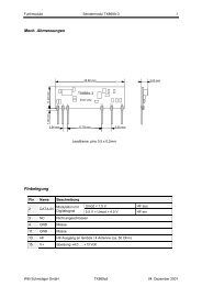
Transceivermodule 1 TRX433-10A / TRX868-10A (Vers. 1.0E ...
Transceivermodule 1 TRX433-10A / TRX868-10A (Vers. 1.0E ...
Transceivermodule 1 TRX433-10A / TRX868-10A (Vers. 1.0E ...

Create successful ePaper yourself
Turn your PDF publications into a flip-book with our unique Google optimized e-Paper software.
<strong>Transceivermodule</strong> 6 <strong>TRX433</strong>-<strong>10A</strong> / <strong>TRX868</strong>-<strong>10A</strong> (<strong>Vers</strong>. <strong>1.0E</strong>)<br />
Linkcontrol mode<br />
Pin 9 (TEST) of the <strong>Transceivermodule</strong> has two functions, one for the flow-control (handshake) and the<br />
second function is the link-control. The link-control signals a valid, bidirectional link to a second partner-<br />
<strong>Transceivermodule</strong>.<br />
If TEST is set high through a resistor, the status of the radio-link to the partnermodem is output on the signal<br />
LINK\.<br />
LINK\ low means radio communication is OK<br />
LINK\ high means no radio communication<br />
Because TEST as well as LINK\ are double used and depending on the application are used as an input or<br />
an output, please take care not to connect two outputs without any current-limitation resistor together and<br />
also prevent the situation of an open input.<br />
As an example we refer to the application schematic of the Evalkit3, where the link-control is realized with a<br />
push-button and a LED.<br />
Important notice:<br />
Pin 9 must be connected with a Pulldown resistor (e.g. 100 k) to GND, so that the configuration mode cannot<br />
be activated unintentional during powerup of the <strong>Transceivermodule</strong>.<br />
If during powerup pin 9 is already high, the configuration mode is activated.<br />
RSSI (Received Signal Strenght indicator)<br />
The voltage at pin 8 (RSSI) is directly proportional to the receiving field intensity. The higher this voltage is<br />
the higher is also the receiving field intensity. The scaling is approx. 29dB/V, the offset or zero point is not<br />
calibrated and depends on the RF-mode.<br />
Powersupply<br />
The Radiotransceiver needs a clean supply voltage of min. 3.5V with a ripple of < 10mVpp.<br />
The power amplifier of the radio transmitter is directly connected to the input supply voltage, the rf-transmitter<br />
power therefore depends a little on the input supply voltage.<br />
If the supply of the <strong>Transceivermodule</strong> is switched, the voltage must always sink to 0V, before switching on<br />
the supply again. The supply voltage must rise within max. 50ms from 0V to 3.5V, so that the integrated<br />
microcontroller starts correctly. The voltage may never fall below 3.3 V, not even for a short time.<br />
If this cannot be ensured, the supply voltage must be supervised by a Voltagedetector, which ties the MCLR\<br />
input low as soon as the voltage drops below approx. 3.3V. See also application example with Evalkit3.<br />
Datainterface with 5V Systems<br />
The logic levels of the <strong>Transceivermodule</strong> are 3.3 Volt, according to the int. voltage regulator. The<br />
Transceiver can work directly at 5Volt systems, however during the high level of the 5V system an additional<br />
small current flows over the internal series resistors into the Transceiver. The input high-levels of the 5V<br />
system must be compatible to the 3.3V logic. See also simplified schematic of the Transceiver<br />
MCLR\ Reset<br />
The microcontroller of the <strong>Transceivermodule</strong> hasn’t got an internal Reset-detector, so the reset pin is<br />
externally accessible. We recommend an external Voltage detector with a trip voltage of > 3.3Volt (for<br />
standard TRX with 3.3V internal voltage regulator). If no such detector is used, please read the datasheet of<br />
the Microchip 16LF648A and ensure that the supply voltage conditions for powerup, brownout etc. can be<br />
met. The most problematic situation exists, when the supply voltage drops below 3.5 Volt and then again<br />
rises to normal condition, without going to nearly zero Volt.<br />
Anyway, with an external voltage detector, these problems are solved.<br />
If the conditions described under paragraph Powersupply are all met, the external reset-controller or voltage<br />
detector can be omitted.