TEC APO 140 - Baader Planetarium
TEC APO 140 - Baader Planetarium
TEC APO 140 - Baader Planetarium

Create successful ePaper yourself
Turn your PDF publications into a flip-book with our unique Google optimized e-Paper software.
<strong>TEC</strong> <strong>APO</strong> <strong>140</strong><br />
OWNER’S MANUAL<br />
2005<br />
“This telescope is closer to optical perfection more<br />
than any instrument I have ever used before.”<br />
R.Renzi, Italy.
IMPORTANT - PLEASE READ THIS MANUAL BEFORE USING YOUR TELESCOPE<br />
SAFETY WARNINGS<br />
Do not look at the sun through the telescope<br />
Viewing the sun through the telescope without special equipment (Solar Filter) will cause<br />
permanent visual impairment and telescope parts damage.<br />
Do not disassemble<br />
Disassembly of telescope could result in personal injury and telescope malfunction.<br />
CONTACT INFORMATION<br />
If you have any questions or need assistance - please contact us:<br />
Phone: 303 273 9322 • Fax: 303 273 0204<br />
E-mail: tec@telescopengineering.com • Web site: www.telescopengineering.com<br />
User’s group site: http://groups.yahoo.com/group/tec-scopes<br />
Address: Telescope Engineering Company • 15730 West 6-th Ave. Golden CO, 80401. USA<br />
<strong>TEC</strong> <strong>APO</strong> <strong>140</strong> <strong>TEC</strong>HNICAL SPECIFICATIONS<br />
Clear aperture 5.5” / <strong>140</strong> mm<br />
Focal length 980 mm<br />
Focal ratio 7.0<br />
Image scale 3.5 arc min/mm<br />
Resolution (theoretical) 0.8 arc sec<br />
Focuser Feather Touch 3545<br />
Eyepiece holder 2” Collet type<br />
Focusing range 4.5” / 114 mm<br />
One turn focus travel Coarse 21.5 mm / Fine 2.3 mm<br />
Back focus distance 6.7” / 170 mm<br />
Focuser load capacity 10 lb<br />
Tube assembly diameter 5.9” / 150 mm<br />
Baffle dia. 7” / 178 mm<br />
TA length (shortest) 34” / 864 mm<br />
Balance point position 14” ± 1” (350 mm ± 25 mm) from the focuser flange (fig. 5).<br />
OTA weight 19 lb / 8.6 kg / (for tube rings - add 2 lb)<br />
Lens coatings: Broad band 7 layers antireflection coating (BBAR)<br />
Price (2005) $4750<br />
Includes : Optical tube assembly, front cover, plug.<br />
OPTIONAL EQUIPMENT (see www.telescopengineering.com for the current prices)<br />
Tube rings $250<br />
ScopeGuard case $350<br />
Aluminum transportation case (Germany) $460<br />
Finderscope bracket with base $120<br />
7x50 finder (Japan) $120<br />
AP finder bracket $60<br />
<strong>TEC</strong> 9” dovetail plate $70<br />
<strong>TEC</strong> 12” dovetail plate $90<br />
Eyepiece Turret $500<br />
Mahogany case for I-Turret $150<br />
Field Flattener $600<br />
1
OVERVIEW<br />
This manual has been written to help you enjoy using your <strong>TEC</strong> <strong>APO</strong> <strong>140</strong> refractor.<br />
<strong>APO</strong> <strong>140</strong> has a number of features that in a given combination are rarely found in one scope:<br />
Precision apochromatic objective with modern coating that makes lenses almost invisible<br />
Retractable baffle<br />
Light tube assembly<br />
FeatherTouch 360° rotatable focuser with coarse and fine focusing<br />
Collet type eyepice holder.<br />
Line of accessories, including:<br />
Precision tube rings with adjustable latches<br />
Dovetail plate (same width and fit as Losmandy plates)<br />
Finder bracket with new principle of finder adjustment<br />
Choice of two kind of cases.<br />
All parts of the telescope, including: optics, coatings, etc. are made in the USA.<br />
GETTING TO KNOW YOUR TELESCOPE<br />
The parts of the telescope and their functions are identified and described below.<br />
1 2 3 4 5 6<br />
7<br />
<strong>TEC</strong> <strong>APO</strong> <strong>140</strong><br />
1 Front Cover. - made of Aluminum, push-pull type. It protects the optics and holds the baffle<br />
during transportation.<br />
2 Retractable Sliding Baffle. This feature makes the<br />
OTA shorter for handling and transportation. The<br />
open end of the baffle is rounded to improve<br />
aerodynamics of the front end of telescope. Rounded<br />
edge creates less turbulence compared to straight<br />
cut baffles.<br />
3 Baffle flange. It holds the baffle with four 4-40<br />
Button Head Screws.<br />
4 Tube assembly. The tube interior is coated with<br />
special light absorbent coating and has 4 sharp edge<br />
baffles, which block internal reflections.<br />
5 OTA Focusing Mounting Flange. (It is part # 6.1 in<br />
the focuser description).<br />
6 Focuser. See following Instructions written by<br />
Detlef Schmidt (Starlight Instruments Inc.).<br />
The focuser’s tube is coated inside with the same<br />
special coating as the tube assembly.<br />
7 Plug. It is a small part that keeps the focuser end closed.<br />
2<br />
To remove cover put<br />
thumb and index fingers<br />
into the sliding latches and<br />
move them in the shown<br />
directions.
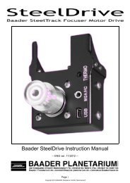
FEATHER TOUCH FOCUSER MODEL 3545<br />
Care and use of the Feather Touch 3545<br />
The Feather Touch 3545 was a collaboration design effort between Telescope Engineering Co.<br />
and Starlight Instruments for <strong>TEC</strong>’s line of fine refractors. It was designed to provide the user<br />
the with the best possible control while focusing using a 9:1 fine focus reduction assembly<br />
along with other features that make the use of the telescope simple and functional. All efforts<br />
were taken to design it with the best available materials and technology to achieve long-lasting<br />
functionality and reliability.<br />
Part Description<br />
6.1 OTA Focuser Mounting Flange<br />
6.2 Focuser Locking Collar<br />
6.3 Locking Collar Stems<br />
6.5 Tension Adjustment Screw<br />
6.6 Finder Base Screw Holes (Plugged<br />
with (2), 8-32 Button Head Screws)<br />
6.7 Focuser Housing<br />
6.8 Coarse Focus Knobs<br />
6.9 Fine Focus Knob<br />
6.10 Draw Tube with mm scale<br />
6.11 Stainless Steel Wear Strips<br />
6.12 Draw Tube End Cap<br />
6.13 Draw Tube End Cap Locking Screws<br />
6.14 Eyepiece Collet Locking Nut<br />
6.15 Eyepiece Collet Sleeve (not shown<br />
being under the plug (fig. 7).<br />
6.1<br />
6.2<br />
6.6<br />
6.7<br />
6.8<br />
6.10<br />
6.11<br />
Description of Design Features<br />
6.12<br />
1. The Feather Touch 3545 achieves excellent<br />
focusing capability using a 9:1<br />
6.13<br />
Planetary Reduction Assembly coupled to a<br />
fine focus knob (fig. 6.9). The fine focus<br />
6.14<br />
knob should be used once the image is<br />
close to focus and final tweaking is<br />
6.15<br />
required.<br />
2. The two coarse focusing knobs (fig. 6.8) 7<br />
on each side of the focuser allow quick<br />
rough positioning of the eyepiece or imaging<br />
equipment. They are coupled to the<br />
rack and pinion set and the fine focus knob.<br />
3. The assembly incorporating the focusing knobs, the pinion and it’s housing is called the<br />
pinion assembly (not shown). This assembly is attached to the focuser housing using (2) 6-32<br />
socket head cap screws. The position of the pinion assembly relative to the rack, is precisely<br />
adjusted by Starlight Instruments using 4 flat bottom set screws (internal to the pinion<br />
assembly) to provide the minimum amount of backlash between the rack and the pinion for<br />
ease of operation. The other adjustment that is made is to align the pinion axis to be parallel<br />
to the rack face.<br />
NOTE: It is possible to reverse the pinion assembly for left handed preference but<br />
Starlight Instruments does not recommend the user reversing this assembly because<br />
of possible misalignment resulting in a loss of performance or possible damage.<br />
Please contact Starlight Instruments or <strong>TEC</strong> if this change is desired.<br />
3<br />
6.3<br />
6.5<br />
6.8<br />
6.9
4. The Feather Touch 3545 focuser is assembled to the OTA via the Focuser Mounting Flange<br />
(fig. 6.1), and the Focuser Locking Collar (fig. 6.2). Loosening the focuser Locking Collar<br />
allows the focuser to be rotated to any position relative to the telescope for ease of use. Once<br />
the focuser has been positioned, it can be locked by turning the Locking Collar by either grabbing<br />
the grooves on this collar or by grabbing the optional Locking Stems and rotating the<br />
Locking Collar clockwise until it is tight. The Locking Stems help to provide a better grip for<br />
tightening the collar. They can however be replaced with the 10-32 Button Head Cap Screws<br />
for a cleaner look if that is desired. NOTE: The focuser can be removed by loosening the<br />
Locking Collar and unscrewing it completely and then pulling the focuser from the Adapter<br />
Flange. This should only be done in rare circumstances and after contacting Starlight<br />
Instruments or <strong>TEC</strong> because of possible damage that may result.<br />
5. The Draw Tube (fig. 6.10) is fitted with 3 Stainless Steel wear strips (fig. 6.11). These<br />
strips provide very low friction between the Housing (fig. 6.7) and the Draw Tube (fig. 6.10).<br />
There is no lubrication required on these parts and an occasional cleaning of the Draw Tube<br />
and the Stainless Steel Wear Strips with a damp paper towel to remove any grit or dirt is<br />
advisable. The design is such, that as the focuser is racked in and out, the wiping action of the<br />
Wear Strips on the mating surfaces tends to be self-cleaning.<br />
6. The drag between the Focuser Housing (fig. 6.7) and the Draw Tube (fig. 6.10) can be<br />
adjusted in using two adjustment methods. The Tension Adjustment Screw can be adjusted<br />
using a 3/16 inch Allen wrench. Only a slight amount of rotation on this screw makes a<br />
notable difference. Tightening this screw will allow larger loads to be lifted without the focuser<br />
moving from the dead weight that may be attached to it and it will also decrease the amount<br />
of deflection during positional changes during long exposures. Generally the factory settings<br />
should be sufficient for most applications.<br />
In addition, adjustment can be done in a simpler way - by tightening a thumb screw (not<br />
shown in picture, but easy to find) under the pinion assembly.<br />
7. In the event that different equipment such as: an optional Field Flattener or AP 2.7"<br />
threaded End Cap (available from Starlight Instruments) is needed at the end of the focuser,<br />
the Draw Tube End Cap (fig. 6.12) can be removed by loosening the (3) 6-32 socket head set<br />
screw and then unscrewing the back.<br />
8. The 2 inch Eyepiece Holder does not use traditional thumb screws. This focuser uses an<br />
Eyepiece Collet Locking Nut (fig. 6.14) and an Eyepiece Collet Sleeve. This design assures that<br />
the eyepiece or imaging equipment is always precisely positioned and held into place during<br />
imaging. To secure your eyepiece, insert the eyepiece into the 2 inch opening making sure<br />
that the nut has been turned counter clock wise to open the collet sleeve and push in the eyepiece.<br />
Tighten the Collet Nut clockwise until it is tight.<br />
WARNING: Failure to tighten the Collet Nut can result in personal injury and/or<br />
damage to equipment. Always make sure that the eyepiece is secured properly during<br />
use.<br />
WARNING: Never point to the sun without proper filtering or without the Front Cover<br />
in place. Failure to do so can result in personal injury or damage to the collet locking<br />
sleeve and/or optics. The Collet Locking Sleeve is plastic and can melt if it gets too<br />
hot. Possible fumes during melting can cause fogging or damage to the optics.<br />
9. If a finder base is to be attached to the focuser housing make sure that the screws being<br />
used are the proper length.<br />
WARNING: If they are too long they will contact the draw tube thereby causing damage<br />
to the anodized surface of the draw tube.<br />
WARRANTY<br />
Starlight Instruments Incorporated guarantees this product to be free of any defects in material<br />
or workmanship for 3 years to the original owner. Disassembly of focuser outside of the<br />
described items voids all warranties.<br />
Starlight Instruments Inc. • P.O. Box 68282, Schaumburg, IL 60168-0282. USA.<br />
Phone: 847-985-9595.<br />
4
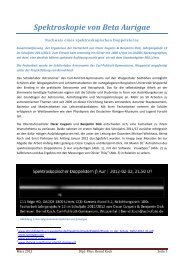
OPTICS<br />
<strong>APO</strong><strong>140</strong> is an Aplanatic Oiled Triplet refractor with ED glass (FPL-53) as a middle element. The<br />
color correction is optimized for visual use with focus shift less than 0.02% from 436nm to<br />
1000nm. Calculated Strehl for<br />
e-line (546nm) is 0.99.<br />
Intereferometry of the first run<br />
lenses showed that the average<br />
Strehl is close to calculated<br />
with a very smooth wave front<br />
and RMS less than 1/50.<br />
plates, autocollimation test with an artificial<br />
star, interferometry, however we do not<br />
supply test results to avoid any kind of<br />
misinterpretations or “numbers” competition<br />
between customers.<br />
Each objective assembled in precision<br />
thermocompensation cell (1), that contains:<br />
Three Lenses Sealed Construction (2) with<br />
a special oil between lenses and Threaded<br />
Ring (3). The Threaded Ring of each objective<br />
is engraved with serial number of OTA.<br />
The optics are collimated at the shop during<br />
assembly and do not require any additional<br />
adjustments. Collimating, assembling<br />
and sealing require special equipment and<br />
techniques and must be done only by qualified<br />
technician.<br />
The oiled design has only two<br />
air-to-glass surfaces. The result<br />
is a higher contrast image<br />
because of much less scatter<br />
and veiling glare due to internal<br />
reflections comparing to<br />
air-spaced objectives.<br />
The outside surfaces of front<br />
and rear lenses are coated with 7 layers of<br />
antireflective<br />
coating, that reduce light reflection to the<br />
average 0.25% in range of 400-700nm.<br />
Shown on the left is a sample of interferometry<br />
of typical objective with appr. RMS less<br />
than 1/50 and wave front error less than<br />
1/10. The lenses are tested during manufacturing<br />
with different methods including: test<br />
1 2 3<br />
WARNING: NEVER TRY TO DISASSEM-<br />
BLE THE OBJECTIVE! DISSASSEMBLY<br />
OF THE OBJECTIVE WILL RESULT IN SERIOUS DAMAGE<br />
TO THE MOST EXPENSIVE PART OF YOUR TELESCOPE - THE OPTICS!<br />
5
ACCESSORIES<br />
TUBE RINGS<br />
CNC machined, black anodized aluminum,<br />
compact and lightweight design with stainless<br />
steel latches (set of two rings weights 750g).<br />
Ring dimensions and hole pattern are shown in<br />
the sketch below. Each ring contains: Upper<br />
Base (1); Latch (2); and Lower Base (3).<br />
Latches for the scopes of the third and forth<br />
run are adjustable. The screw (5) has a Phillips<br />
type head for easy adjustment, the small nut<br />
(4) will hold screw in place after adjustment.<br />
Rings can be attached to the mount with either<br />
<strong>TEC</strong> Dovetail plate, AP or Losmandy plates.<br />
NOTE: From user feedback - it is better and<br />
more safe to keep rings on the OTA all the<br />
time if possible - this way there is no chance<br />
OTA inside the rings, as would be<br />
the case if longer plates were being<br />
used.<br />
The <strong>TEC</strong> Dovetail Plate is compatible<br />
with Losmandy, WYO or Casady<br />
Saddle systems. Two 8-32 security<br />
screws must be installed on each<br />
end of the Plate; these security<br />
screws prevent the dovetail and OTA<br />
from accidentally slipping off the<br />
dovetail holder.<br />
for scratching the tube.<br />
DOVETAIL PLATE<br />
3<br />
4<br />
5<br />
1<br />
2<br />
The Dovetail Plate, like all other accessories for<br />
this telescope, is CNC machined for lightness<br />
(320g) and rigidity from aluminum stock, and<br />
then black anodized for a tough, corrosion-free<br />
surface.<br />
Though having the same width and hole pattern<br />
as Losmandy plates, the <strong>TEC</strong> Dovetail Plate is<br />
only 9" long. The shorter length not only allows<br />
it to be lighter, but also provides you the<br />
convenience of being able to retract the Front<br />
baffle (for storage) without having to move the<br />
6<br />
8-32 threaded holes for security screws
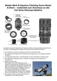
<strong>TEC</strong> FINDERSCOPE BRACKET<br />
The <strong>TEC</strong> Finderscope Bracket is<br />
8 7 6 5<br />
designed to hold a traditional 50mm<br />
optical finder or a Red Dot sight.<br />
This new design requires only 2<br />
thumb screws for alignment. It looks<br />
9<br />
and works in a much more elegant<br />
way. The Finderscope Bracket contains the following parts:<br />
Finder Base (1), that attaches to the focuser with two 8-32<br />
4<br />
screws; Holding Knob (2), tightening this knob will hold the<br />
3<br />
Finder Arm (3) with Finder Holder (4) to the Finder Base. The<br />
2<br />
Finder (9) is spring-loaded with spring and screw covered by<br />
1<br />
Spring Cover (6).The Finder holder has two 10-32 set screws (8) on the objective side and<br />
two 10-32 Alignment Thumb Screws (5). A special insert (7) must be installed in the finder’s<br />
body. <strong>TEC</strong> performs this installation for free in any brands. Please note that finder’diameter<br />
should not be larger than 2”.<br />
When attaching the finder base to<br />
the focuser housing make sure to<br />
use screws of the proper length.<br />
WARNING:<br />
If the screws are too long,<br />
they will contact the draw<br />
tube and damage its anodized<br />
surface !<br />
Shown on above picture is the<br />
Astro-Physics Finder bracket with<br />
Orion 9x50 finder. This<br />
combination is less expensive and<br />
does not require insert installation.<br />
The Red Dot sights could also be<br />
installed. This installation requires<br />
fewer parts: only a Finder Base<br />
and a Finder Arm with knob.<br />
Finder base<br />
7
acket (without removing it). 2” AP<br />
diagonal, 5 of 2” eyepieces. Dimensions<br />
of AL case are: 10” x 13.5” x 37”.<br />
Weight (net) -13lb. Weight with scope,<br />
rings, plate, finder+ bracket, AP diagonal,<br />
2" eyepieces appr. - 40lb.<br />
ACCESSORIES:<br />
Eyepiece Turret with Mahogany case.<br />
Precision holder for five 1.25" eyepieces.<br />
Diagonal mirror made of Sitall or Quartz.<br />
Case safely holds six 1.25" eyepieces<br />
and I-Turret. Case dimensions:<br />
5.5" x 8.25" x 10.75"; weight - 2lb.<br />
This new component will let you<br />
change your favourite eyepieces<br />
very fast - just click from one to<br />
the next one and enjoy observing.<br />
TELESCOPE CASES<br />
After you have finished observing and are looking<br />
for a safe place to store your telescope, the best<br />
place would be a case. We have two types available:<br />
Scopeguard Case shown on the left - a foam-fitted<br />
carrying case that will keep your scope in the<br />
best condition for years. You can even keep the<br />
Tube rings and plate on the OTA - this set up fits in<br />
the Case.<br />
The second case, shown below, is Aluminum transportation<br />
case made in Germany. It has hard foam<br />
interior with a few special sections that allow to<br />
hold the <strong>APO</strong><strong>140</strong> with rings, plate and Finder with<br />
Latest updates for this manual or new<br />
accessories are available on our web: www.telescopengineering.com<br />
and on <strong>TEC</strong>-scopes users group: http://groups.yahoo.com/group/tec-scopes.<br />
8
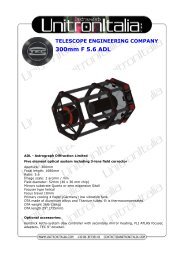
FOCUSING DIAGRAM<br />
4,5" FOCUS TRAVEL<br />
Focusing tube is completely "IN"<br />
Unvignetted field dia. ~1.0"<br />
7,0" BACK FOCUS<br />
Focusing tube is completely "OUT"<br />
Unvignetted field dia. ~1.6"<br />
3" long extension tube is required<br />
for straight through viewing<br />
With the 2" diagonal focusing tube is in the middle position<br />
Unvignetted field dia. ~1.4"<br />
With the Field Flattener focusing tube is in the middle position<br />
Unvignetted field dia. ~2.4"<br />
9<br />
110.<br />
2,5"<br />
camera depth 85.0mm
Cleaning :<br />
The tube assembly and front baffle are powder coated, to clean them use water<br />
with a soap or mineral spirits (paint thinner); do not use Acetone or other strong<br />
chemicals. Please contact us if you need the lens to be cleaned.<br />
Handling :<br />
Handling telescope around and it’s transportation to the observing site requires<br />
careful handling.<br />
If you find any problems, or have any comments - please call us for assistance.<br />
Telescope Engineering Company is commited to serving it’s<br />
customers after sale for unlimited time.<br />
Yuri Petrunin, <strong>TEC</strong> President.<br />
<strong>TEC</strong> <strong>APO</strong><strong>140</strong> UPDATES<br />
RUN I (2002) RUN II (2003) RUN III (2004) RUN IV (2005)<br />
QTY plan/made 40/35 40/40 >100 >100<br />
OTA price $4000 $4250 $4600 $4750<br />
Tube dia. 152.4mm 152.4mm 150.1mm 150.1mm<br />
OTA weight 18 lb 18 lb 18.5 lb 18.5 lb<br />
Tube type drawn drawn machined machined<br />
Labeling no yes yes yes<br />
Color OTA / Baffle white/black white/white white/white white/white<br />
Internal paint ultra flat black / spray ultra flat black / spray special coating special coating<br />
Internal baffles 3 4 4 4<br />
Rings latches fixed fixed adjustable adjustable<br />
Cover / material / style Plastic / screw-type Plastic / screw-type Al / push-pull Al / push-pull<br />
“A virtually perfect textbook image both in and out of focus. This is my first time to experience such<br />
perfection in this regard. My subjective evaluation put the optics at 1/8 to 1/16th wave...” M.T., Japan.<br />
10