Formation of Impact Craters - Lunar and Planetary Institute
Formation of Impact Craters - Lunar and Planetary Institute
Formation of Impact Craters - Lunar and Planetary Institute

Create successful ePaper yourself
Turn your PDF publications into a flip-book with our unique Google optimized e-Paper software.
The processes by which large impact craters form, <strong>and</strong><br />
the sudden releases <strong>of</strong> huge quantities <strong>of</strong> energy involved,<br />
cannot be duplicated in the laboratory, <strong>and</strong>, fortunately, no<br />
such structure has formed during recorded human history.<br />
All our knowledge about large impact structures is therefore<br />
indirect, <strong>and</strong> it has come from combining several areas <strong>of</strong><br />
once-separate research: theoretical <strong>and</strong> experimental studies<br />
<strong>of</strong> shock waves (for reviews <strong>and</strong> literature, see Melosh,<br />
1989), experimental production <strong>of</strong> small craters (e.g., Gault<br />
et al., 1968; Gault, 1973; Holsapple <strong>and</strong> Schmidt, 1982, 1987;<br />
papers in Roddy et al., 1977), <strong>and</strong> geological studies <strong>of</strong> larger<br />
terrestrial impact structures (Shoemaker, 1963; Dence, 1968;<br />
Dence et al., 1977; Grieve <strong>and</strong> Cintala, 1981; Grieve et al.,<br />
1981; Schultz <strong>and</strong> Merrill, 1981; Stöffler et al., 1988). The<br />
cratering process is complex, many details are still uncertain,<br />
<strong>and</strong> neither calculations nor predictions can be made with<br />
firm confidence. But these studies provide the essential basis<br />
for underst<strong>and</strong>ing how impact craters form <strong>and</strong> for deciphering<br />
the geological features they display.<br />
3.1. SHOCK WAVES AND<br />
CRATER FORMATION<br />
The general term “impact crater” is used here to designate<br />
a hypervelocity impact crater, the structure formed by<br />
a cosmic projectile that is large enough <strong>and</strong> coherent enough<br />
to penetrate Earth’s atmosphere with little or no deceleration<br />
<strong>and</strong> to strike the ground at virtually its original cosmic<br />
velocity (>11 km/s). Such projectiles tend to be relatively<br />
large, perhaps >50 m in diameter for a stony object <strong>and</strong> >20 m<br />
for a more coherent iron one.<br />
Smaller projectiles, typically a few meters or less in size,<br />
behave differently in passing through the atmosphere. They<br />
lose most or all <strong>of</strong> their original velocity <strong>and</strong> kinetic energy<br />
in the atmosphere through disintegration <strong>and</strong> ablation, <strong>and</strong><br />
they strike the ground at speeds <strong>of</strong> no more than a few hun-<br />
<strong>Formation</strong> <strong>of</strong> <strong>Impact</strong> <strong>Craters</strong><br />
17<br />
<strong>Formation</strong> <strong>of</strong> <strong>Impact</strong> <strong>Craters</strong> 17<br />
dred meters per second. In such a low-velocity impact, the<br />
projectile penetrates only a short distance into the target (depending<br />
on its velocity <strong>and</strong> the nature <strong>of</strong> the target material),<br />
<strong>and</strong> the projectile’s momentum excavates a pit that is<br />
slightly larger than the projectile itself. The projectile survives,<br />
more or less intact, <strong>and</strong> much <strong>of</strong> it is found in the<br />
bottom <strong>of</strong> the pit. Such pits, sometimes called penetration<br />
craters or penetration funnels, are typically less than a few<br />
tens <strong>of</strong> meters in diameter.<br />
Examples <strong>of</strong> these features include Brenham (Kansas),<br />
the many small pits made by the Sikhote-Alin (Russia) meteorite<br />
shower in 1947, <strong>and</strong> the pit dug by the largest piece<br />
<strong>of</strong> the Kirin (China) meteorite fall in 1976. The process <strong>of</strong><br />
excavation is strictly a mechanical one, <strong>and</strong> high-pressure<br />
shock waves are not produced.<br />
In sharp contrast, a hypervelocity impact crater starts to<br />
form at the instant that an extraterrestrial object strikes the<br />
ground surface at its original cosmic velocity. These impact<br />
velocities are much greater than the speed <strong>of</strong> sound in the<br />
target rocks, <strong>and</strong> the crater is produced by intense shock<br />
waves that are generated at the point <strong>of</strong> impact <strong>and</strong> radiate<br />
outward through the target rocks. Shock waves are intense,<br />
transient, high-pressure stress waves that are not produced<br />
by ordinary geological processes (for details, see Melosh, 1989,<br />
Chapter 3 <strong>and</strong> references therein). Peak shock pressures produced<br />
at typical cosmic encounter velocities may reach several<br />
hundred GPa. These pressure are far above the stress<br />
levels (~1 GPa) at which terrestrial rocks undergo normal<br />
elastic <strong>and</strong> plastic deformation, <strong>and</strong> the shock waves produce<br />
unique <strong>and</strong> permanent deformation effects in the rocks<br />
through which they pass.<br />
The shock waves radiate from the impact point at high<br />
velocities that may exceed 10 km/s, much greater than the<br />
speed <strong>of</strong> sound in the target rocks. As they exp<strong>and</strong>, they interact<br />
with the original ground surface to set a large volume<br />
<strong>of</strong> the target rock into motion, thus excavating the impact<br />
crater. The formation <strong>of</strong> an impact crater by shock waves,
18 Traces <strong>of</strong> Catastrophe<br />
<strong>and</strong> the immediate modification <strong>of</strong> the newly formed crater<br />
by gravity <strong>and</strong> rock mechanics, is a complex <strong>and</strong> continuous<br />
process. However, it is convenient to divide this process,<br />
somewhat arbitrarily, into three distinct stages, each dominated<br />
by different forces <strong>and</strong> mechanisms: contact <strong>and</strong> compression,<br />
excavation, <strong>and</strong> modification (Gault et al., 1968;<br />
see also Melosh, 1989, Chapters 4, 5, <strong>and</strong> 8).<br />
3.1.1. Contact/Compression Stage<br />
This stage begins at the instant that the leading edge <strong>of</strong><br />
the moving projectile makes contact with the ground surface.<br />
If the target is solid rock, the projectile is stopped in a<br />
fraction <strong>of</strong> a second <strong>and</strong> penetrates no more than 1–2× its<br />
own diameter (Fig. 3.1) before its immense kinetic energy is<br />
transferred to the target rocks by shock waves generated at<br />
the interface between projectile <strong>and</strong> target (Kieffer <strong>and</strong><br />
Simonds, 1980; O’Keefe <strong>and</strong> Ahrens, 1982, 1993; Melosh, 1989,<br />
Chapter 4).<br />
The general features <strong>of</strong> this conversion <strong>of</strong> kinetic energy<br />
into shock waves have been determined from experiments<br />
<strong>and</strong> theoretical studies (e.g., O’Keefe <strong>and</strong> Ahrens, 1975, 1977,<br />
1993; Ahrens <strong>and</strong> O’Keefe, 1977; papers in Roddy et al., 1977;<br />
Melosh, 1989, Chapter 4), although many details are still not<br />
Fig. 3.1. Contact/compression stage: shock-wave generation<br />
<strong>and</strong> projectile deformation. Theoretical cross-section showing<br />
calculated conditions immediately after the impact <strong>of</strong> a large,<br />
originally spherical, projectile (stippled) onto a uniform target. The<br />
projectile has penetrated about half its diameter into the target,<br />
<strong>and</strong> intense shock waves (pressures in GPa) are radiating outward<br />
into the target from the interface. The projectile itself has become<br />
intensely compressed, <strong>and</strong> similar shock waves from the interface<br />
are spreading toward the rear <strong>of</strong> the projectile. When this shock<br />
wave reaches the rear <strong>of</strong> the projectile, it will be reflected forward<br />
as a tensional wave or rarefaction, unloading the projectile <strong>and</strong><br />
allowing it to transform, virtually instantaneously, into melt <strong>and</strong><br />
vapor. The original model, developed for large lunar impact events<br />
(O’Keefe <strong>and</strong> Ahrens, 1975), represents conditions about 1 s after<br />
the impact <strong>of</strong> a 46-km-diameter anorthosite projectile at 15 km/s<br />
onto a gabbroic anorthosite target, but similar conditions will be<br />
produced by smaller impacts <strong>and</strong> other material compositions.<br />
(Modified from Melosh, 1989, Fig. 4.1a, p. 47.)<br />
well understood. One clear result is that, as one set <strong>of</strong> shock<br />
waves is transmitted outward from the interface into the target<br />
rocks, a complementary shock wave is reflected back into<br />
the projectile (Fig. 3.1) (Melosh, 1989, Chapter 4; O’Keefe<br />
<strong>and</strong> Ahrens, 1993).<br />
The shock waves transmitted into the target rocks lose<br />
energy rapidly as they travel away from the impact point.<br />
Two factors are involved in this energy loss: (1) the exp<strong>and</strong>ing<br />
shock front covers an increasingly larger hemispherical<br />
area with increasing radial distance, thus reducing the overall<br />
energy density; (2) additional energy is lost to the target<br />
rocks through heating, deformation, <strong>and</strong> acceleration. The<br />
peak pressures <strong>of</strong> the shock waves therefore also drop rapidly<br />
with distance from the impact point. Theoretical models<br />
(Melosh, 1989, pp. 60–66) <strong>and</strong> geological studies <strong>of</strong><br />
shock-metamorphosed rocks in individual structures (Dence,<br />
1968; Robertson, 1975; Grieve <strong>and</strong> Robertson, 1976; Dence et<br />
al., 1977; Robertson <strong>and</strong> Grieve, 1977; Dressler et al., 1998)<br />
indicate that the peak shock-wave pressure (P s ) drops exponentially<br />
with the distance R from the impact point according<br />
to an equation <strong>of</strong> the form P s α R –n . Various field <strong>and</strong><br />
laboratory studies indicate a dependence <strong>of</strong> R –2 to R –4.5 ; the<br />
exact value <strong>of</strong> the exponent depends on projectile size <strong>and</strong><br />
impact velocity (Ahrens <strong>and</strong> O’Keefe, 1977).<br />
On the basis <strong>of</strong> these studies, it is possible to regard the<br />
impact point as surrounded by a series <strong>of</strong> concentric, roughly<br />
hemispherical shock zones, each zone distinguished by a<br />
certain range <strong>of</strong> peak shock pressure (Fig. 3.2) <strong>and</strong> characterized<br />
by a unique suite <strong>of</strong> shock-metamorphic effects produced<br />
in the rocks. At the impact point, peak shock-wave<br />
pressures may exceed 100 GPa (= 1000 kbar or 1 Mbar) for<br />
typical cosmic encounter velocities, producing total melting,<br />
if not vaporization, <strong>of</strong> the projectile <strong>and</strong> a large volume <strong>of</strong><br />
surrounding target rock. Further outward, pressures <strong>of</strong> 10–<br />
50 GPa may exist over distances <strong>of</strong> many kilometers from<br />
the impact point, producing distinctive shock-deformation<br />
effects in large volumes <strong>of</strong> unmelted target rock.<br />
At even greater distances from the impact point, the peak<br />
shock-wave pressures eventually drop to about 1–2 GPa<br />
(Kieffer <strong>and</strong> Simonds, 1980). At this point, near the eventual<br />
crater rim, the shock waves become regular elastic waves or<br />
seismic waves, <strong>and</strong> their velocity drops to that <strong>of</strong> the velocity<br />
<strong>of</strong> sound in the target rocks (typically 5–8 km/s). These seismic<br />
waves can be transmitted throughout the entire Earth,<br />
like similar waves generated by earthquakes <strong>and</strong> volcanic<br />
eruptions. Because <strong>of</strong> their low pressures, they do not produce<br />
any permanent deformation <strong>of</strong> the rocks through which<br />
they pass. However, seismic waves may produce fracturing,<br />
brecciation, faulting, <strong>and</strong> (near the surface) l<strong>and</strong>slides, <strong>and</strong><br />
the results may be difficult to distinguish from those <strong>of</strong> normal<br />
geological processes.<br />
The duration <strong>of</strong> the contact/compression stage is determined<br />
by the behavior <strong>of</strong> the shock wave that was reflected<br />
back into the projectile from the projectile/target interface<br />
(Fig. 3.1) (Melosh, 1989, pp. 57–59). When this shock wave<br />
reaches the back end <strong>of</strong> the projectile, it is reflected forward<br />
into the projectile as a rarefaction or tensional wave (also
called a release wave). As the release wave passes through<br />
the projectile from back to front, it unloads the projectile<br />
from the high shock pressures it had experienced. Because<br />
the shock pressures, <strong>and</strong> the associated temperatures, have<br />
been so high, this release results in the virtually complete<br />
melting <strong>and</strong> vaporization <strong>of</strong> the projectile. At the instant at<br />
which the release wave reaches the front end <strong>of</strong> the projectile,<br />
the whole projectile is unloaded, <strong>and</strong> the release wave<br />
continues forward into the target <strong>and</strong> begins to decompress<br />
it as well. This point, at which the release wave reaches the<br />
front <strong>of</strong> the projectile <strong>and</strong> begins to enter the adjacent compressed<br />
target, is taken as the end <strong>of</strong> the complete contact/<br />
compression stage.<br />
The contact/compression stage lasts no more than a few<br />
seconds, even for impacts <strong>of</strong> very large objects. The time<br />
required for the shock wave to travel from the projectile/<br />
target interface to the rear edge <strong>of</strong> the projectile is approxi-<br />
,,<br />
,,<br />
,,,<br />
,,,<br />
, ,,,<br />
<strong>Formation</strong> <strong>of</strong> <strong>Impact</strong> <strong>Craters</strong> 19<br />
Fig. 3.2. Contact/compression stage: initial shock-wave pressures <strong>and</strong> excavation flow lines around impact point. Schematic crosssection<br />
showing peak shock pressure isobars (pressures in GPa) developed in the target around the impact point near the end <strong>of</strong> the<br />
contact/compression stage. The originally spherical projectile, after penetrating about two diameters into the target, has been almost<br />
completely destroyed <strong>and</strong> converted to melt <strong>and</strong> vapor. Shock waves radiating from the projectile-target interface decline rapidly outward<br />
in peak pressure (isobars in GPa on left side <strong>of</strong> cavity), creating concentric, approximately hemispherical zones <strong>of</strong> distinctive shock effects<br />
(right side <strong>of</strong> cavity). From the original interface outward, these zones involve: (1) melting (>50 GPa) <strong>and</strong> formation <strong>of</strong> a large melt unit;<br />
(2) shock-deformation effects (5–50 GPa); (3) fracturing <strong>and</strong> brecciation (1–5 GPa). The subsequent excavation stage involves two<br />
processes: (1) upward ejection (spalling) <strong>of</strong> large near-surface fragments <strong>and</strong> smaller ejecta (ejecta curtain) (upward-pointing arrows<br />
above ground surface); (2) subsurface flow <strong>of</strong> target material to form the transient crater (arrow paths crossing isobars at left side).<br />
(Modified from Melosh, 1989, Fig. 5.4, p. 64.)<br />
mately equal to the time it takes the projectile to travel the<br />
distance <strong>of</strong> one diameter at its original velocity. Even for<br />
large projectiles, this time is short: 2 s for a 50-km-diameter<br />
projectile traveling at 25 km/s, <strong>and</strong> less than 0.01 s for a<br />
100-m-diameter object traveling at the same speed. The<br />
additional time required for the release wave to travel from<br />
the rear to the front edge will be no more than a few times<br />
this value, depending on the properties <strong>of</strong> projectile <strong>and</strong> target<br />
rock (Melosh, 1989, pp. 48 <strong>and</strong> 58). For most impact<br />
events, the entire contact/compression stage is over in less<br />
than a second.<br />
After the release wave has reached the front end <strong>of</strong> the<br />
projectile <strong>and</strong> unloaded it completely, the projectile itself plays<br />
no further role in the formation <strong>of</strong> the impact crater, <strong>and</strong> the<br />
actual excavation <strong>of</strong> the crater is carried out by the shock<br />
waves exp<strong>and</strong>ing through the target rocks. The vaporized<br />
portion <strong>of</strong> the projectile may exp<strong>and</strong> out <strong>of</strong> the crater as part
20 Traces <strong>of</strong> Catastrophe<br />
<strong>of</strong> a vapor plume (Melosh, 1989, pp. 68–71), <strong>and</strong> the remainder,<br />
virtually all melted, may be violently mixed into the<br />
melted <strong>and</strong> brecciated target rocks.<br />
3.1.2. Excavation Stage: The Transient Crater<br />
The brief contact/compression stage grades immediately<br />
into a longer excavation stage, during which the actual impact<br />
crater is opened up by complex interactions between<br />
the exp<strong>and</strong>ing shock waves <strong>and</strong> the original ground surface<br />
(Fig. 3.3) (Melosh, 1989, Chapter 5; Grieve, 1991). As the<br />
contact/compression stage ends, the projectile is surrounded<br />
by a roughly hemispherical envelope <strong>of</strong> shock waves that<br />
exp<strong>and</strong> rapidly through the target rock. Because the projectile<br />
has penetrated a finite distance into the target, the center<br />
<strong>of</strong> this hemisphere actually lies within the original target<br />
rock at a point below the original ground surface.<br />
Within this hemispherical envelope, the shock waves that<br />
travel upward <strong>and</strong> intersect the original ground surface are<br />
reflected downward as rarefactions (release waves). In a nearsurface<br />
region where the stresses in the tensional release<br />
wave exceed the mechanical strength <strong>of</strong> the target rocks,<br />
the release wave is accompanied by fracturing <strong>and</strong> shattering<br />
<strong>of</strong> the target rock (Fig. 3.2). This reflection process also<br />
converts some <strong>of</strong> the initial shock-wave energy to kinetic<br />
energy, <strong>and</strong> the rock involved is accelerated outward, much<br />
<strong>of</strong> it as individual fragments traveling at high velocities<br />
(Fig. 3.4).<br />
These complex processes drive the target rock outward<br />
from the impact point, producing a symmetric excavation<br />
flow around the center <strong>of</strong> the developing structure. Exact<br />
flow directions vary with location within the target rocks<br />
(Fig. 3.4). In the upper levels, target material moves dominantly<br />
upward <strong>and</strong> outward. At lower levels, target material<br />
moves dominantly downward <strong>and</strong> outward. These movements<br />
quickly produce a bowl-shaped depression (the transient<br />
cavity or transient crater) in the target rocks (Maxwell,<br />
1977; Grieve at al., 1977; Grieve <strong>and</strong> Cintala, 1981; Melosh,<br />
1989, pp. 74–78).<br />
The transient crater is divided into approximately equal<br />
upper <strong>and</strong> lower zones (Figs. 3.4 <strong>and</strong> 3.5). Within the upper<br />
ejection zone, velocities imparted to the target rocks may be<br />
as high as several kilometers per second, high enough to excavate<br />
the fragmented material <strong>and</strong> to eject it beyond the<br />
rim <strong>of</strong> the final crater (Grieve et al., 1977; Dence et al., 1977;<br />
Kieffer <strong>and</strong> Simonds, 1980; Melosh, 1989, pp. 74–76). Even<br />
at significant distances from the impact point, shock pressures<br />
<strong>and</strong> the resulting ejection velocities remain high enough<br />
(>100 m/s) to eject material. For this reason, the diameter <strong>of</strong><br />
the final crater is many times larger (typically 20–30×) than<br />
the diameter <strong>of</strong> the projectile itself.<br />
At deeper levels, tensional stresses in the release waves<br />
are lower. As a result, fracturing is less pronounced, excavation<br />
flow velocities are lower, <strong>and</strong> the excavation flow lines<br />
themselves are not oriented to eject material beyond the crater<br />
rim (Fig. 3.4). This region forms a displaced zone in<br />
which material is driven downward <strong>and</strong> outward more or<br />
less coherently.<br />
Both zones in the transient crater continue to exp<strong>and</strong>,<br />
accompanied by the uplift <strong>of</strong> near-surface rocks to form the<br />
transient crater rim, as long as the exp<strong>and</strong>ing shock waves<br />
<strong>and</strong> release waves are strong enough to eject or displace material<br />
from the developing cavity. However, these waves continually<br />
lose energy by deforming <strong>and</strong> ejecting the target rocks<br />
through which they pass. Eventually, a point is reached at<br />
which the shock <strong>and</strong> release waves can no longer excavate or<br />
displace target rock. At that point the growth <strong>of</strong> the transient<br />
crater ceases. There is an instant <strong>of</strong> theoretical balance<br />
in which the energies <strong>of</strong> the shock wave no longer act, <strong>and</strong><br />
the waiting forces <strong>of</strong> gravity <strong>and</strong> rock mechanics have not<br />
yet reasserted themselves. At this instant, the transient crater<br />
reaches its maximum extent, the excavation stage ends,<br />
<strong>and</strong> the subsequent modification stage begins immediately.<br />
The excavation stage, although longer than the contact/<br />
compression stage, is still brief by geological st<strong>and</strong>ards. If<br />
the near-surface excavation flow has a minimum average velocity<br />
<strong>of</strong> 1 km/s, then a 200-km-diameter transient crater<br />
can be excavated in less than 2 min. More detailed calculations<br />
(Melosh, 1989, p. 123) indicate that excavation <strong>of</strong> a<br />
l-km-diameter crater (e.g., Barringer Meteor Crater [Arizona])<br />
will occur in about 6 s, while a 200-km-diameter<br />
crater requires only about 90 s.<br />
The concept <strong>of</strong> the transient crater has been developed<br />
from a combination <strong>of</strong> theoretical studies (Melosh, 1989,<br />
Chapter 5) <strong>and</strong> geological investigations (Dence, 1968; Grieve<br />
<strong>and</strong> Cintala, 1981; Grieve et al., 1981). The ideal transient<br />
crater is a bowl-shaped depression with a structurally uplifted<br />
rim (Figs. 3.4 <strong>and</strong> 3.5). Its shape is approximately<br />
hemispherical but is actually a paraboloid <strong>of</strong> revolution<br />
Fig. 3.3. Development <strong>of</strong> a simple impact structure. Series <strong>of</strong> cross-section diagrams showing progressive development <strong>of</strong> a small,<br />
bowl-shaped simple impact structure in a horizontally layered target: (a) contact/compression stage: initial penetration <strong>of</strong> projectile,<br />
outward radiation <strong>of</strong> shock waves; (b) start <strong>of</strong> excavation stage: continued expansion <strong>of</strong> shock wave into target; development <strong>of</strong> tensional<br />
wave (rarefaction or release wave) behind shock wave as the near-surface part <strong>of</strong> original shock wave is reflected downward from ground<br />
surface; interaction <strong>of</strong> rarefaction wave with ground surface to accelerate near-surface material upward <strong>and</strong> outward; (c) middle <strong>of</strong><br />
excavation stage: continued expansion <strong>of</strong> shock wave <strong>and</strong> rarefaction wave; development <strong>of</strong> melt lining in exp<strong>and</strong>ing transient cavity;<br />
well-developed outward ejecta flow (ejecta curtain) from the opening crater; (d) end <strong>of</strong> excavation stage: transient cavity reaches maximum<br />
extent to form melt-lined transient crater; near-surface ejecta curtain reaches maximum extent, <strong>and</strong> uplifted crater rim develops; (e) start<br />
<strong>of</strong> modification stage: oversteepened walls <strong>of</strong> transient crater collapse back into cavity, accompanied by near-crater ejecta, to form<br />
deposit <strong>of</strong> mixed breccia (breccia lens) within crater; (f ) final simple crater: a bowl-shaped depression, partially filled with complex<br />
breccias <strong>and</strong> bodies <strong>of</strong> impact melt. Times involved are a few seconds to form the transient crater (a)–(d), <strong>and</strong> minutes to hours for the<br />
final crater (e)–(f ). Subsequent changes reflect the normal geological processes <strong>of</strong> erosion <strong>and</strong> infilling.
,,,<br />
,,,<br />
<strong>Formation</strong> <strong>of</strong> <strong>Impact</strong> <strong>Craters</strong> 21
,,<br />
,,,<br />
,,,<br />
,,<br />
22 Traces <strong>of</strong> Catastrophe<br />
Fig. 3.4. Excavation stage: formation <strong>of</strong> transient crater. Theoretical cross section showing development <strong>of</strong> the transient crater<br />
immediately after the contact/compression stage. Original peak shock pressures (units in GPa) around the impact point are shown for<br />
simplicity as hemispherical isobars (for details, see Fig. 3.2). Complex interactions <strong>of</strong> the shock wave, the ground surface, <strong>and</strong> the<br />
subsequent rarefaction wave produce an outward excavation flow (dashed arrows) that opens up the transient crater. In the upper part <strong>of</strong><br />
this region (excavated zone; ruled area), target material is fractured, excavated, <strong>and</strong> ejected beyond the transient crater rim. In the lower<br />
region (displaced zone), target material is driven downward <strong>and</strong> outward, more or less coherently, <strong>and</strong> does not reach the surface. This<br />
model yields two important geological results: (1) ejected material is derived only from the upper part (approximately the top one-third<br />
to one-half ) <strong>of</strong> the transient cavity; (2) because the excavation flow lines in the excavated zone cut across the initially hemispherical shock<br />
isobars, ejected material will reflect a wide range <strong>of</strong> original shock pressures <strong>and</strong> deformation effects, ranging from simple fracturing to<br />
complete melting <strong>and</strong> vaporization. (Modified from Grieve, 1987, Fig. 5; Hörz et al., 1991, Fig. 4.3a, p. 67.)<br />
,,<br />
,,<br />
Fig. 3.5. Transient crater: locations <strong>of</strong> shock-metamorphosed materials. Cross section through a theoretical transient crater, showing<br />
discrete zones from which various shock-metamorphosed materials are derived. The “vaporized” zone closest to the original impact point<br />
(stippled) contains a mixture <strong>of</strong> vaporized target rock <strong>and</strong> projectile, which exp<strong>and</strong>s upward <strong>and</strong> outward into the atmosphere as a vapor<br />
plume. The adjacent “melt” zone (solid black) consists <strong>of</strong> melt that moves downward <strong>and</strong> then outward along the floor <strong>of</strong> the final<br />
transient cavity (for details, see Fig. 6.2). Material in the upper “ejected” zones on either side <strong>of</strong> the melt zone, which contains a range <strong>of</strong><br />
shock-metamorphic effects, is ejected outward to <strong>and</strong> beyond the transient crater rim. The lower “displaced” zone moves downward <strong>and</strong><br />
outward to form the zone <strong>of</strong> parautochthonous rocks below the floor <strong>of</strong> the final transient crater. H at = the final transient crater depth;<br />
H exc = the depth <strong>of</strong> excavation, which is significantly less than the total depth. (From Melosh, 1989, Fig. 5.13, p. 78.)
(Dence, 1973). Its maximum depth is approximately onethird<br />
its diameter, <strong>and</strong> this proportion seems to remain<br />
approximately constant for craters <strong>of</strong> widely different size<br />
(Maxwell, 1977; Cr<strong>of</strong>t, 1985).<br />
The theoretical instant <strong>of</strong> ideal overall balance in a transient<br />
crater at the end <strong>of</strong> the excavation stage may not be<br />
actually attained during formation <strong>of</strong> a real crater. For example,<br />
in these models, the maximum diameter is normally<br />
attained after the maximum depth is reached. Subsequent<br />
modification <strong>of</strong> one part <strong>of</strong> an actual transient crater might<br />
therefore begin while other parts are still being excavated.<br />
Even so, the transient crater is a key concept in models <strong>of</strong><br />
crater formation. All impact structures, regardless <strong>of</strong> their<br />
final size or the complexity <strong>of</strong> their subsequent development,<br />
are assumed to pass through the transient-crater stage, making<br />
this stage <strong>of</strong> critical importance in comparing impact<br />
structures <strong>of</strong> different sizes or on different planets. Defining<br />
the transient crater is also an essential step in determining<br />
critical characteristics <strong>of</strong> an impact structure: its original<br />
(pre-erosion) diameter <strong>and</strong> depth, the energy <strong>of</strong> impact, the<br />
size <strong>and</strong> velocity <strong>of</strong> the projectile, the distribution <strong>of</strong> shock<br />
pressures <strong>and</strong> shock effects within the crater, the amount <strong>of</strong><br />
material melted <strong>and</strong> ejected during formation <strong>of</strong> the crater,<br />
the amount <strong>of</strong> structural uplift during formation <strong>of</strong> the central<br />
peak <strong>of</strong> complex impact structures, <strong>and</strong> the depth from<br />
which excavated materials were derived.<br />
3.1.3. Modification Stage<br />
The excavation stage ends when the transient crater has<br />
grown to its maximum size, <strong>and</strong> the subsequent modification<br />
stage begins immediately. The exp<strong>and</strong>ing shock waves<br />
have now decayed to low-pressure elastic stress waves beyond<br />
the crater rim, <strong>and</strong> they play no further part in the<br />
crater development. Instead, the transient crater is immediately<br />
modified by more conventional factors like gravity <strong>and</strong><br />
rock mechanics.<br />
The immediate part <strong>of</strong> the modification stage, during<br />
which the major impact-related changes occur, lasts only<br />
slightly longer than the excavation stage: less than a minute<br />
for a small structure, a few minutes for a large one (Melosh,<br />
1989, Chapter 8, pp. 141–142). (One simple definition is<br />
that the modification stage ends “when things stop falling.”)<br />
However, the modification stage has no clearly marked end,<br />
<strong>and</strong> the modification processes <strong>of</strong> uplift <strong>and</strong> collapse merge<br />
gradually into the normal processes <strong>of</strong> geological mass movement,<br />
isostatic uplift, erosion, <strong>and</strong> sedimentation.<br />
3.2. SIMPLE AND COMPLEX<br />
IMPACT STRUCTURES<br />
The extent to which the transient crater is altered during<br />
the modification stage depends on its size <strong>and</strong> (to a lesser<br />
extent) on the structure <strong>and</strong> properties <strong>of</strong> the target rock.<br />
Small transient craters are altered chiefly by the collapse <strong>of</strong><br />
their upper walls, <strong>and</strong> the shape <strong>of</strong> the final crater is little<br />
changed from that <strong>of</strong> the original transient crater. In larger<br />
<strong>Formation</strong> <strong>of</strong> <strong>Impact</strong> <strong>Craters</strong> 23<br />
structures, modification may involve major structural<br />
changes: uplift <strong>of</strong> the central part <strong>of</strong> the floor <strong>and</strong> major<br />
peripheral collapse around the rim. Depending on the extent<br />
to which the transient crater is modified, three distinct<br />
types <strong>of</strong> impact structures can be formed: simple craters,<br />
complex craters, <strong>and</strong> multiring basins.<br />
3.2.1. Simple <strong>Craters</strong><br />
The smallest impact structures occur as bowl-shaped depressions<br />
(simple craters) less than a few kilometers across,<br />
which help to preserve the shape <strong>and</strong> dimensions <strong>of</strong> the original<br />
transient cavity (Figs. 1.1 <strong>and</strong> 3.6). In evolving to a simple<br />
crater, the transient crater is modified only by minor collapse<br />
<strong>of</strong> the steep upper walls into the crater cavity <strong>and</strong> by<br />
redeposition <strong>of</strong> a minor amount <strong>of</strong> ejected material in the<br />
crater. As a result, the crater diameter may increase by as<br />
much as 20%, but the original transient crater depth remains<br />
largely unaffected (Fig. 3.7) (Melosh, 1989, p. 129).<br />
During modification, the simple crater is immediately<br />
filled, to perhaps half its original depth, by a mixture <strong>of</strong> redeposited<br />
(fallback) ejecta <strong>and</strong> debris slumped in from the<br />
walls <strong>and</strong> rim (Fig. 3.7). This crater-filling unit, variously<br />
called the breccia lens or crater-fill breccia, is a mixture <strong>of</strong><br />
rock fragments, both shocked <strong>and</strong> unshocked, together with<br />
fragments or lenses <strong>of</strong> shock-melted rock (impact melt).<br />
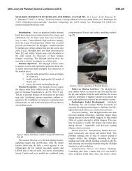
Fig. 3.6. A simple lunar impact crater. This small, well-preserved<br />
crater (Moltke: D = 7 km) shows features typical <strong>of</strong> simple impact<br />
craters: a circular outline, a bowl-like shape, an uplifted rim, <strong>and</strong><br />
hummocky deposits <strong>of</strong> ejecta around the rim. In the relatively low<br />
gravity <strong>of</strong> the Moon, this structure formed as a simple crater; a<br />
terrestrial structure <strong>of</strong> the same diameter, formed under Earth’s<br />
higher gravity, would have formed as a complex crater with a central<br />
uplift. (Apollo 10 image AS10-29-4324.)
24 Traces <strong>of</strong> Catastrophe<br />
Fig. 3.7. Simple impact structure: locations <strong>of</strong> impactite types. Schematic cross section <strong>of</strong> a typical simple impact structure, showing<br />
the simple bowl shape <strong>and</strong> the locations <strong>of</strong> various types <strong>of</strong> impactites in <strong>and</strong> around the structure. The parautochthonous rocks below<br />
the true crater floor are fractured <strong>and</strong> brecciated but generally show no distinctive shock effects, except in a small zone (fine vertical<br />
ruling) in the center <strong>of</strong> the structure. The crater is filled, to approximately half its original height, with a variety <strong>of</strong> allogenic breccias <strong>and</strong><br />
impact melts, which forms the crater-fill units or the breccia lens. A thinner layer <strong>of</strong> ejected material (fallout ejecta) overlies the uplifted<br />
crater rim <strong>and</strong> surrounds the crater. This unit is easily eroded <strong>and</strong> is present only in the youngest <strong>and</strong> best-preserved structures. D = final<br />
crater diameter, which is 10–20% greater than the diameter <strong>of</strong> the original, premodification transient crater; d t = true depth <strong>of</strong> the final<br />
crater, which is approximately the depth <strong>of</strong> the original transient crater; d a = apparent depth <strong>of</strong> the crater, or the depth from the final rim<br />
to the top <strong>of</strong> the crater-fill units. The diagram represents the state <strong>of</strong> the final crater before any subsequent geological effects, e.g., erosion,<br />
infilling. The model is based on drilling studies at Barringer Meteor Crater (Arizona) (Roddy et al., 1975; Roddy, 1978), Brent Crater<br />
(Canada) (Dence, 1968; Grieve <strong>and</strong> Cintala, 1981), <strong>and</strong> similar structures (e.g., Masaitis et al., 1980; Gurov <strong>and</strong> Gurova, 1991). (From<br />
Grieve, 1987, Fig. 1.)<br />
Depending on the subsequent geological history, the breccia<br />
lens may be eroded or may be covered <strong>and</strong> preserved by a<br />
cap <strong>of</strong> later sedimentary fill.<br />
3.2.2. Complex <strong>Craters</strong><br />
The bowl-shaped form <strong>of</strong> simple craters appears only in<br />
relatively small structures less than a few kilometers across.<br />
Larger impact structures (complex craters) display a different<br />
<strong>and</strong> more complicated form, characterized by a centrally<br />
uplifted region, a generally flat floor, <strong>and</strong> extensive inward<br />
collapse around the rim (Figs. 1.3, 3.8, <strong>and</strong> 3.9) (Dence, 1968;<br />
Grieve et al., 1977, 1981; Grieve, 1991). For terrestrial structures,<br />
the transition between simple <strong>and</strong> complex craters<br />
occurs at a diameter <strong>of</strong> about 4 km in massive crystalline<br />
rocks, but at only about 2 km in sediments. (However, these<br />
values apply only to Earth. The transition diameter varies<br />
inversely with gravitational acceleration, <strong>and</strong> it is different<br />
on different planets.) The larger impact events that form<br />
complex craters apparently release enough energy to overcome<br />
the fundamental strength <strong>of</strong> the target rocks over a<br />
large volume beneath the large transient crater. As a result,<br />
late-stage modification involves complex interactions between<br />
shock-wave effects, gravity, <strong>and</strong> the strength <strong>and</strong> structure<br />
<strong>of</strong> the target rocks, <strong>and</strong> the modification is characterized<br />
by outward, inward, <strong>and</strong> upward movements <strong>of</strong> large volumes<br />
<strong>of</strong> the subcrater rocks.<br />
The details <strong>of</strong> these interactions are uncertain, but the<br />
general result is that the original bowl-shaped transient crater<br />
is immediately modified as deep-seated rocks beneath<br />
the center <strong>of</strong> the transient crater rise to form a central uplift<br />
(Dence, 1968; Grieve et al., 1981). At the same time, rocks<br />
around the periphery <strong>of</strong> the transient crater collapse downward<br />
<strong>and</strong> inward along concentric faults to form one or more<br />
depressed rings (ring grabens) <strong>and</strong> a series <strong>of</strong> terraces along<br />
the outer margins <strong>of</strong> the final structure (Fig. 3.10). [A simple<br />
model <strong>of</strong> the formation <strong>of</strong> a complex crater <strong>and</strong> its central<br />
uplift is presented by the familiar slow-motion movies <strong>of</strong> a<br />
drop <strong>of</strong> liquid hitting a liquid surface (e.g., Melosh, 1989,<br />
p. 148; Taylor, 1992, p. 168). There is the same initial cavity<br />
formation, the same outward <strong>and</strong> downward ejection <strong>of</strong> target<br />
material, the same upward rebound <strong>of</strong> the central cavity<br />
floor, <strong>and</strong> the same collapse <strong>of</strong> the periphery back into the<br />
cavity. However, in impact events, these processes take place<br />
in solid rock <strong>and</strong> may operate over distances <strong>of</strong> tens to hundreds<br />
<strong>of</strong> kilometers.]<br />
The idea that such rapid deformation <strong>and</strong> subsequent<br />
uplift can occur in large volumes <strong>of</strong> crustal rocks has been<br />
difficult for many geologists to appreciate. Key evidence has<br />
come from studies <strong>of</strong> impact structures formed in sedimentary<br />
rocks, in which the actual uplift <strong>of</strong> key stratigraphic<br />
markers has been established beyond question through drilling<br />
<strong>and</strong> geophysical studies (e.g., Milton et al., 1972, 1996a,b;
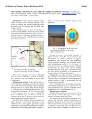
Fig. 3.8. A complex lunar crater. This relatively young crater<br />
(Theophilus: D = 100 km) displays well-preserved features that<br />
are typical <strong>of</strong> complex impact structures: a central uplift, a scalloped<br />
circular outline, ruggedly terraced walls with possible l<strong>and</strong>slide<br />
deposits inside the rim, <strong>and</strong> hummocky ejecta deposits just outside<br />
the rim. This view also indicates the continuing nature <strong>of</strong><br />
lunar cratering; an older impact crater (upper right) has been partly<br />
destroyed by Theophilus, while a younger small crater has formed<br />
within Theophilus itself (near rim, lower right). The flat dark<br />
area in the background (upper left) is made up <strong>of</strong> lava flows covering<br />
part <strong>of</strong> Mare Nectaris. The spiral-like rod at left center is an<br />
instrument boom on the Apollo 16 spacecraft, from which this<br />
orbital picture was taken. (Apollo 16 image AS16-M-0692.)<br />
Grieve et al., 1981; Grieve <strong>and</strong> Pilkington, 1996). Geological<br />
studies have also established that the amount <strong>of</strong> actual stratigraphic<br />
uplift (SU) in impact structures is about one-tenth<br />
the final diameter (D) <strong>of</strong> the structure. A detailed statistical<br />
relation derived from studies <strong>of</strong> well-constrained complex<br />
impact structures (Grieve et al., 1981, p. 44) is SU = 0.06 D 1.1<br />
(both SU <strong>and</strong> D are in kilometers). A subsequent analysis,<br />
using more craters (Grieve <strong>and</strong> Pilkington, 1996, p. 404),<br />
gave SU = 0.086 D 1.03. The two equations are virtually identical,<br />
<strong>and</strong> a value <strong>of</strong> SU = 0.1 D is a reasonable approximation<br />
to either. For large (D = 100–200 km) impact structures,<br />
these relations imply that the crustal rocks beneath the structure<br />
are uplifted vertically by 10–20 km during the impact<br />
event. An uplift <strong>of</strong> this magnitude has been estimated for<br />
the Vredefort (South Africa) structure on geological grounds<br />
(Reimold <strong>and</strong> Gibson, 1996; Therriault et al., 1997; Turtle <strong>and</strong><br />
Pierazzo, 1998).<br />
Both theoretical <strong>and</strong> field studies indicate that central<br />
uplifts form in only a few minutes, almost instantaneously<br />
by geological st<strong>and</strong>ards, even in the largest structures (Melosh,<br />
1989, pp. 129 <strong>and</strong> 141–142). Theoretical studies also suggest<br />
that the central uplifts <strong>of</strong> structures 200–300 km in<br />
<strong>Formation</strong> <strong>of</strong> <strong>Impact</strong> <strong>Craters</strong> 25<br />
Fig. 3.9. A complex impact basin on Venus. A large, wellpreserved<br />
multiring impact basin on the surface <strong>of</strong> Venus<br />
(Meitner: D = 150 km) is revealed beneath the planet’s opaque<br />
atmosphere by the imaging radar system <strong>of</strong> the Magellan spacecraft.<br />
Meitner, the third-largest impact structure identified on<br />
Venus, shows a flat smooth (dark-colored) interior, two circular<br />
rings, <strong>and</strong> a rough, irregular blanket <strong>of</strong> lobate ejecta (light-colored).<br />
The crater was formed on a surface <strong>of</strong> smooth plains, possibly<br />
underlain by lava flows <strong>and</strong> cut by abundant parallel fractures<br />
(white lines). (Magellan image F-MIDRP .55S319;201.)<br />
diameter, such as Vredefort (South Africa), formed in less<br />
than 15 minutes (Melosh, 1989, pp. 141–142; Turtle <strong>and</strong><br />
Pierazzo, 1998).<br />
Despite the extensive evidence that central uplifts do form<br />
in large impact structures, the details <strong>of</strong> the process are still<br />
the subject <strong>of</strong> continuing uncertainty <strong>and</strong> active debate<br />
(Dence, 1968; Grieve et al., 1981; Melosh, 1989, Chapter 8;<br />
Hörz et al., 1991; Spudis, 1993). Even so fundamental a quantity<br />
as the ratio between the diameter <strong>of</strong> the initial transient<br />
crater <strong>and</strong> the diameter <strong>of</strong> the final complex impact structure<br />
has not been well established; values estimated by various<br />
workers, using both theoretical <strong>and</strong> geological studies,<br />
range from about 0.5 to 0.7 (see, e.g., Therriault et al., 1997,<br />
Table 2).<br />
At larger crater diameters, the resulting structures, <strong>and</strong><br />
especially the centrally uplifted area, become even more complicated.<br />
As the crater size increases the character <strong>of</strong> the central<br />
uplift changes, <strong>and</strong> the single central peak is progressively<br />
replaced by a more complex series <strong>of</strong> concentric rings <strong>and</strong><br />
basins. At least three types <strong>of</strong> complex impact structures can<br />
be distinguished with increasing crater diameter: centralpeak<br />
structures, central-peak-basin structures, <strong>and</strong> peak-
26 Traces <strong>of</strong> Catastrophe<br />
Fig. 3.10. Development <strong>of</strong> a complex impact structure. Series <strong>of</strong> cross sections showing progressive development <strong>of</strong> a large, complex<br />
impact structure in a horizontally layered target: (a) formation <strong>of</strong> a large transient crater by the excavation process is virtually identical to<br />
transient crater formation in smaller structures (compare with Fig. 3.3a–d); (b) initial development <strong>of</strong> central uplift during the subsequent<br />
modification stage; (c) start <strong>of</strong> peripheral collapse, accompanied by continuing development <strong>of</strong> the central uplift <strong>and</strong> the thinning <strong>and</strong><br />
draping <strong>of</strong> the original melt layer (black) over the uplifted rocks; (d) final structure, which is <strong>of</strong> the central-uplift type, consists <strong>of</strong> a central<br />
uplift <strong>of</strong> deeper rocks, surrounded by a relatively flat plain <strong>and</strong> by a terraced rim produced by inward movement along stepped normal<br />
faults. The central uplift is surrounded by an annular deposit <strong>of</strong> allogenic breccias <strong>and</strong> impact melt (black), which may be absent from the<br />
central peak itself. An ejecta layer (stippled) covers the target rocks around the structure. The diameter <strong>of</strong> the final structure, measured at<br />
the outer rim beyond the outermost fault, may be 1.5–2× the diameter <strong>of</strong> the original transient crater. This central-peak morphology is<br />
observed in terrestrial structures ranging from about 2–25 km in diameter; larger structures tend to develop one or more concentric rings<br />
within the crater (for details, see text).
ing basin structures (Grieve at al., 1981; Melosh, 1989,<br />
Chapter 8; Spudis, 1993). As the terms suggest, these structures<br />
are characterized by the initial development <strong>of</strong> a basin<br />
in the central peak <strong>and</strong> eventually by the complete conversion<br />
<strong>of</strong> the central peak area to a ring structure (Figs. 1.3,<br />
3.9, <strong>and</strong> 3.11).<br />
These distinctions, <strong>and</strong> the transition diameters at which<br />
they occur, have been most clearly established on airless bodies<br />
like the Moon, where even large ancient structures have<br />
been well preserved (Figs. 3.6, 3.8, <strong>and</strong> 3.11) (e.g., Taylor,<br />
1982, 1992; Melosh, 1989, pp. 131–135; Spudis, 1993). Classification<br />
<strong>of</strong> large terrestrial structures (e.g., papers in Schultz<br />
<strong>and</strong> Merrill, 1981; Spudis, 1993, pp. 24–41) is more difficult<br />
<strong>and</strong> uncertain, because the impact structures, especially their<br />
critical upper parts, tend to be removed by erosion or buried<br />
by later sediments. Furthermore, the critical diameters at<br />
which one form changes to another depend inversely on the<br />
planetary gravity, making it difficult to apply data from structures<br />
on other planets to terrestrial features. For example,<br />
the transition between simple <strong>and</strong> complex craters occurs at<br />
about 20 km diameter on the Moon but at only 2–4 km on<br />
Fig. 3.11. A lunar impact basin. This large impact structure<br />
(Schrödinger: D = 320 km) is located on the lunar farside near<br />
the Moon’s South Pole. Although ancient <strong>and</strong> highly degraded,<br />
it still preserves features distinctive <strong>of</strong> larger complex impact<br />
structures: a central uplift <strong>and</strong> terraced walls. However, in this<br />
large structure, the central uplift appears as an interior peak ring<br />
about 150 km in diameter (arrows), in sharp contrast to the simpler<br />
central peak formed in smaller complex structures. (<strong>Lunar</strong> Orbiter<br />
image LO-IV-8M.)<br />
<strong>Formation</strong> <strong>of</strong> <strong>Impact</strong> <strong>Craters</strong> 27<br />
Earth. The subsequent transition between a central-peakbasin<br />
structure to a peak-ring structure occurs at about 150–<br />
200 km on the Moon, but at only about 20–25 km on Earth.<br />
Despite the various difficulties, it has been possible to<br />
establish rough boundaries for different types <strong>of</strong> terrestrial<br />
complex structures (Grieve et al., 1981, p. 42, Fig. 2). These<br />
limits, <strong>and</strong> some typical examples, are: central-peak structures<br />
(D = 4–22 km) [Steinheim (Germany), Sierra Madera<br />
(Texas)]; central-peak-basin structures (D = 22–30 km)<br />
[Mistastin (Canada)]; peak-ring-basin structures (D = 30–<br />
62 km) [West Clearwater (Canada); Fig. 1.3]. These values<br />
are only approximations, <strong>and</strong> they will almost certainly change<br />
as more structures are studied in detail <strong>and</strong> as the formation<br />
<strong>of</strong> complex craters is better understood.<br />
3.2.3. Multiring Basins<br />
The largest planetary impact structures so far identified<br />
have diameters <strong>of</strong> a few hundred kilometers to more than<br />
1000 km (e.g., papers in Schultz <strong>and</strong> Merrill, 1981; Melosh,<br />
1989, Chapter 9; Spudis, 1993). In contrast to smaller impact<br />
structures, they appear as huge geological bulls-eyes,<br />
composed <strong>of</strong> multiple concentric uplifted rings <strong>and</strong> intervening<br />
down-faulted valleys (ring grabens) (Fig. 3.12). These<br />
features, designated multiring basins, are defined as structures<br />
that have two or more interior rings in addition to the<br />
outer rim <strong>of</strong> the structure.<br />
Multiring impact basins have been produced by the impact<br />
<strong>of</strong> projectiles tens to hundreds <strong>of</strong> kilometers in diameter,<br />
<strong>and</strong> they date mainly from an early period in the solar<br />
system (>3.9 Ga), when such large objects were more abundant<br />
<strong>and</strong> collisions were more frequent. The best multiring<br />
basins are best observed on planets with well-preserved ancient<br />
surfaces, such as the Moon, Mercury, parts <strong>of</strong> Mars,<br />
<strong>and</strong> some <strong>of</strong> the moons <strong>of</strong> Jupiter. Mare Orientale, on the<br />
Moon, with a diameter <strong>of</strong> at least 900 km, is one <strong>of</strong> the most<br />
prominent <strong>and</strong> best-known multiring basins (Fig. 3.12),<br />
but even larger features exist, such as the Valhalla Basin<br />
(D ~4000 km) on Jupiter’s icy moon Callisto. In addition,<br />
there are numerous large basins in the solar system that<br />
do not display a pronounced multiring structure, possibly<br />
because they have been deeply eroded since they formed.<br />
These include the Caloris Basin (Mercury; D = 1300 km),<br />
the Argyre Basin (Mars; D > 900 km) (Fig. 1.9), <strong>and</strong> the<br />
recently identified South Pole-Aitken Basin on the Moon<br />
(D ~2500 km).<br />
On the Moon, the transition to multiring basins occurs<br />
at diameters <strong>of</strong> about 400–600 km. Because the transition<br />
diameters for different crater forms vary inversely with planetary<br />
gravity, this observation implies that multiring basins<br />
should begin to form on Earth at crater diameters greater<br />
than about 100 km. Because the few terrestrial impact structures<br />
in this size range have been deeply eroded or buried<br />
(e.g., Fig. 1.4), it has not yet been possible to demonstrate<br />
clearly that any multiring basins exist on the Earth. The<br />
few possible c<strong>and</strong>idates (<strong>and</strong> their current estimated diameters)<br />
are Manicouagan (Canada, 100 km), Popigai (Russia,<br />
100 km), Vredefort (South Africa, >200 km), Sudbury
28 Traces <strong>of</strong> Catastrophe<br />
Fig. 3.12. A lunar multiring impact basin. One <strong>of</strong> the largest,<br />
freshest, youngest, <strong>and</strong> best-known multiring impact basins in the<br />
solar system, Mare Orientale (D = 930 km) lies on the boundary<br />
between the Earth-facing lunar nearside (right) <strong>and</strong> the lunar<br />
farside. The structure, formed at about 3.8 Ga, is bounded by an<br />
outer ring about 930 km in diameter (Cordillera Mountains), <strong>and</strong><br />
inner rings with diameters <strong>of</strong> 620, 480, <strong>and</strong> 320 km can be<br />
distinguished. Mare Orientale is surrounded by radial features<br />
(especially at lower right) that may have been produced by the<br />
low-angle ejection <strong>of</strong> large blocks <strong>of</strong> excavated material. The<br />
postimpact history <strong>of</strong> the structure is also complex, <strong>and</strong> much <strong>of</strong><br />
the area inside the rings has been modified by later volcanic activity.<br />
The flat dark areas at upper right are the younger lava flows that<br />
cover Oceanus Procellarum. (<strong>Lunar</strong> Orbiter image LO-IV-187M.)<br />
(Canada, >200 km), <strong>and</strong> Chicxulub (Mexico, >180 km). It<br />
has not proved possible to establish beyond question the<br />
multiring character <strong>of</strong> these structures for various reasons,<br />
including deep erosion, postcrater deformation, or insufficient<br />
geological study. The strongest current c<strong>and</strong>idate for a<br />
terrestrial multiring structure is Chicxulub, which, although<br />
buried, appears well preserved (Sharpton et al., 1993, 1996b;<br />
Morgan et al., 1997).<br />
Multiring basins represent the most energetic <strong>and</strong> catastrophic<br />
impact events in the solar system, <strong>and</strong> the postimpact<br />
movements — upward, downward, <strong>and</strong> inward — <strong>of</strong><br />
the target rock that modify the transient crater are far more<br />
complex <strong>and</strong> widespread than in smaller structures. It is therefore<br />
not surprising that the formation <strong>of</strong> multiring basins is<br />
even more uncertain <strong>and</strong> hotly debated than is the origin <strong>of</strong><br />
smaller complex impact structures (e.g., papers in Schultz<br />
<strong>and</strong> Merrill, 1981; Melosh, 1989, Chapter 9; Spudis, 1993).<br />
For example, it is not clear whether the transition between<br />
smaller impact structures <strong>and</strong> multiring basins is a<br />
natural development with increasing crater diameter (Herrick<br />
et al., 1997), or whether multiring basins only form when<br />
special conditions are present within the target, e.g., a crustmantle<br />
structure with a weak layer (asthenosphere) at depth<br />
within the planet (see Melosh, 1989, pp. 176–180). Nor is it<br />
understood why some planetary features in the 1000–2000km-diameter<br />
range have a pronounced multiring form<br />
(Fig. 3.12) <strong>and</strong> others do not (Fig. 1.9). Finally, it is not yet<br />
established whether multiring impact structures — ancient<br />
or modern — do exist on Earth <strong>and</strong> which large structures<br />
they may be.<br />
3.3. SUBSEQUENT DEVELOPMENT OF<br />
IMPACT STRUCTURES<br />
When the crater formation process ends, the resulting<br />
circular structure, whether simple or complex, consists <strong>of</strong><br />
deformed subcrater rocks covered by an ejecta blanket outside<br />
the crater <strong>and</strong> with crater-fill deposits (usually a mixture<br />
<strong>of</strong> breccias <strong>and</strong> bodies <strong>of</strong> impact melt) within it (Figs. 3.7<br />
<strong>and</strong> 3.13). This assemblage <strong>of</strong> distinctive near-surface rocks<br />
is immediately subject to more normal geological processes:<br />
erosion, burial, <strong>and</strong> tectonic deformation. If the crater<br />
forms on l<strong>and</strong> <strong>and</strong> remains exposed after formation,<br />
erosion will quickly remove the surface ejecta blanket <strong>and</strong><br />
destroy any surviving meteorite fragments. At the same time,<br />
however, a lake may form in the crater depression, covering<br />
the crater-fill material with a preserving cap <strong>of</strong> sediments,<br />
e.g., as at Brent (Canada) (Dence, 1968; Grieve, 1978) <strong>and</strong><br />
the Ries Crater (Germany) (von Engelhardt, 1990).<br />
If the original impact site is covered by water, the formation<br />
<strong>and</strong> subsequent history <strong>of</strong> the resulting crater may be<br />
more complex. At the moment <strong>of</strong> impact, the overlying layer<br />
<strong>of</strong> water will be excavated with the underlying bedrock, <strong>and</strong><br />
the development <strong>of</strong> the crater <strong>and</strong> the deposition <strong>of</strong> the impact-produced<br />
rock units will be modified by the immediate<br />
<strong>and</strong> violent resurge <strong>of</strong> this displaced water back into the crater<br />
cavity (Therriault <strong>and</strong> Lindström, 1995; Lindström et al.,<br />
1996). If the crater remains below the water level, it will<br />
immediately begin to fill with sediments, <strong>and</strong> its subsequent<br />
history will depend on whether it remains below water level<br />
(continuous sediment filling) or is uplifted at some future<br />
time (beginning <strong>of</strong> erosion). A number <strong>of</strong> such submarine<br />
impact structures have now been recognized; some have subsequently<br />
been raised above sea level [e.g., Lockne (Sweden)<br />
(Therriault <strong>and</strong> Lindström, 1995; Lindström et al., 1996)]<br />
<strong>and</strong> others still remain buried [e.g., Montagnais (Canada)<br />
(Jansa <strong>and</strong> Pe-Piper, 1987); the Chesapeake Bay Crater<br />
(USA) (Poag, 1996, 1997); <strong>and</strong> the recently discovered<br />
Mjølnir structure (Norway) in the Barents Sea (Dypvik et<br />
al., 1996)].
<strong>Formation</strong> <strong>of</strong> <strong>Impact</strong> <strong>Craters</strong> 29<br />
Fig. 3.13. Complex impact structure: locations <strong>of</strong> impactite types. Schematic radial cross section across a complex impact structure <strong>of</strong><br />
the central-uplift type, from the central uplift (right) to the outer, downfaulted rim (left). (Vertical scale is exaggerated.) The subcrater<br />
parautochthonous rocks, exposed in the central uplift, are highly fractured <strong>and</strong> brecciated <strong>and</strong> may contain distinctive shock features such<br />
as shatter cones. These rocks may also contain widespread pseudotachylite breccias <strong>and</strong> dike-like intrusive bodies <strong>of</strong> allogenic breccias<br />
<strong>and</strong> impact melts. Larger <strong>and</strong> thicker subhorizontal units <strong>of</strong> allogenic breccias <strong>and</strong> melts occur as an annular unit <strong>of</strong> crater-fill material<br />
that covers the parautochthonous rocks between the central uplift <strong>and</strong> the rim. The bulk <strong>of</strong> these crater-fill deposits consist <strong>of</strong> melt-free<br />
lithic breccias, with lesser amounts <strong>of</strong> melt-bearing suevite breccias. The melt component in the crater-fill deposits becomes more<br />
abundant toward the center <strong>and</strong> upward, <strong>and</strong> a discrete layer <strong>of</strong> impact melt (solid black) may occur at or toward the top <strong>of</strong> the crater fill.<br />
(Modified from Stöffler et al., 1988, Fig. 12, p. 290.)<br />
Because impact is a near-surface process, the deformation<br />
associated with impact structures dies away rapidly<br />
with depth. Typical impact structures are relatively shallow,<br />
<strong>and</strong> impact-produced rocks form comparatively thin units.<br />
The distinctive rock types <strong>and</strong> shock effects in a structure<br />
tens <strong>of</strong> kilometers in diameter may extend only a few kilometers<br />
below the original ground surface. <strong>Impact</strong> structures<br />
are therefore especially vulnerable to erosion. Initial erosion<br />
will preferentially remove the near-surface ejecta deposits<br />
<strong>and</strong> the distinctively shocked <strong>and</strong> melted materials they contain,<br />
thus rapidly destroying the most convincing evidence<br />
for impact. Deeper erosion over longer periods <strong>of</strong> time will<br />
eventually produce major destructive changes in the crater.<br />
The breccias <strong>and</strong> melt units that fill the crater, <strong>and</strong> the distinctive<br />
shocked materials they contain, together with any<br />
protecting cap <strong>of</strong> sediments, will be reduced to small remnants<br />
or completely removed. The original circular outline<br />
will disappear. Eventually, all trace <strong>of</strong> the crater will be removed<br />
except for the weakly shocked subcrater rocks. If<br />
erosion continues long enough, the whole impact structure<br />
will be erased.<br />
<strong>Impact</strong> structures that are not destroyed by erosion may<br />
be entirely filled <strong>and</strong> buried by younger sediments, so that<br />
their detection depends on geophysical methods <strong>and</strong> drilling<br />
rather than on surface field geology. About one-third <strong>of</strong><br />
the presently known impact structures are subsurface (Grieve,<br />
1991, 1997; Grieve <strong>and</strong> Masaitis, 1994; Grieve et al., 1995);<br />
they were first discovered during geophysical explorations,<br />
<strong>and</strong> their impact origin has been verified by the discovery <strong>of</strong><br />
shocked rocks in drill core samples. This group includes several<br />
continental structures that are actual or potential petroleum<br />
producers [Ames (Oklahoma); Avak (Alaska); Marquez<br />
(Texas); Red Wing Creek (North Dakota)] (Don<strong>of</strong>rio, 1997),<br />
as well as a few submarine impact structures [e.g., Montagnais<br />
(Canada) (Jansa <strong>and</strong> Pe-Piper, 1987)]. Several large <strong>and</strong> relatively<br />
young buried impact structures have also been identified<br />
by geophysical techniques: the 90-km-diameter<br />
Chesapeake Bay Crater (USA) (Poag, 1996, 1997); the larger<br />
(>180-km diameter) Chicxulub structure (Mexico), which<br />
is associated with the K/T event (Hildebr<strong>and</strong> et al., 1991;<br />
Sharpton et al., 1992; papers in Ryder et al., 1996); <strong>and</strong> the<br />
large (>70 km?) Morokweng structure (South Africa) (Corner<br />
et al., 1997; Koeberl et al., 1997a). Many more impact<br />
structures remain to be found, <strong>and</strong> the evidence for their<br />
existence may already be sitting unrecognized in existing<br />
drill cores <strong>and</strong> geophysical records around the world.<br />
<strong>Impact</strong> structures may also be caught up in subsequent<br />
tectonic deformation, with varying results. Horizontal compression<br />
may deform the original circular shape, making study<br />
<strong>and</strong> interpretation more difficult [as at Sudbury (Canada)].
30 Traces <strong>of</strong> Catastrophe<br />
Tectonism can also break up regions <strong>of</strong> original shocked rocks<br />
<strong>and</strong> disperse them as large discrete areas across the geological<br />
l<strong>and</strong>scape [e.g., the Beaverhead (Idaho) structure<br />
(Hargraves et al., 1990; Fiske et al., 1994)]. Sufficient tectonism<br />
<strong>and</strong> metamorphism could destroy even large impact<br />
structures or make them totally unrecognizable.<br />
Geologists must therefore be prepared to recognize impact<br />
structures in all states <strong>of</strong> preservation, from young, fresh,<br />
well-exposed circular structures filled with distinctive shocked<br />
breccias to older features in which distinctive shock effects<br />
are scattered, barely recognizable, or deeply buried. It is essential<br />
to be able to recognize the variety <strong>of</strong> distinctive shock<br />
effects associated with impact structures <strong>and</strong> to underst<strong>and</strong><br />
where different types <strong>of</strong> shock effects may be located in the<br />
original crater.