Jupiter System Observer Mission Study: Final Report - Lunar and ...
Jupiter System Observer Mission Study: Final Report - Lunar and ...
Jupiter System Observer Mission Study: Final Report - Lunar and ...

You also want an ePaper? Increase the reach of your titles
YUMPU automatically turns print PDFs into web optimized ePapers that Google loves.
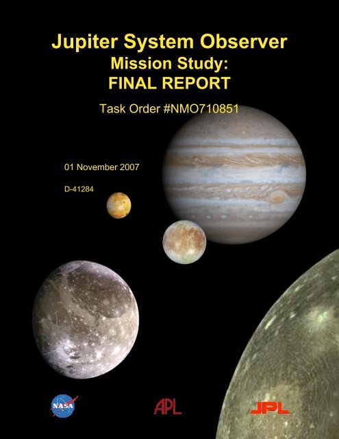
<strong>Jupiter</strong> <strong>System</strong> <strong>Observer</strong><br />
<strong>Mission</strong> <strong>Study</strong>:<br />
FINAL REPORT<br />
Task Order #NMO710851<br />
01 November 2007<br />
D-41284
2007 JUPITER SYSTEM OBSERVER MISSION STUDY: FINAL REPORT 01 NOVEMBER 2007<br />
Task Order #NMO710851 TABLE OF CONTENTS<br />
Table of Contents<br />
FACT SHEET.............................................................................................................................v<br />
1.0 EXECUTIVE SUMMARY ..........................................................................................1-1<br />
1.1 Introduction ......................................................................................................1-1<br />
1.2 <strong>Study</strong> Approach ................................................................................................1-1<br />
1.3 Science Definition.............................................................................................1-1<br />
1.4 Architecture Development ................................................................................1-2<br />
1.5 <strong>Mission</strong> Concept ...............................................................................................1-3<br />
1.6 Planning Payload ..............................................................................................1-3<br />
1.7 Spacecraft.........................................................................................................1-3<br />
1.8 Project Implementation.....................................................................................1-4<br />
1.9 Conclusion........................................................................................................1-4<br />
2.0 JUPITER SYSTEM SCIENCE GOALS AND OBJECTIVES......................................2-1<br />
2.1 Introduction: The Jovian <strong>System</strong>.......................................................................2-1<br />
2.1.1 Science Traceability ..........................................................................2-3<br />
2.1.2 JSO SDT Science Strategy <strong>and</strong> Structure...........................................2-3<br />
2.2 Science Background, Goals, <strong>and</strong> Objectives......................................................2-5<br />
2.2.1 The Jovian Atmosphere .....................................................................2-5<br />
2.2.2 The Jovian Magnetosphere ..............................................................2-10<br />
2.2.3 Io Torus...........................................................................................2-13<br />
2.2.4 Galilean Satellites—Surfaces <strong>and</strong> Interiors ......................................2-14<br />
2.3 Scientific Advancement Achieved by JSO ......................................................2-27<br />
3.0 MISSION ARCHITECTURE ASSESSMENT .............................................................3-1<br />
3.1 Discriminating Architectural Elements..............................................................3-1<br />
3.2 Preliminary <strong>Mission</strong> Architectures Selection.....................................................3-1<br />
3.3 Intermediate <strong>Mission</strong> Architectures Selection ...................................................3-2<br />
3.3.1 Jovian Tour .......................................................................................3-2<br />
3.3.2 Sub-Satellite......................................................................................3-2<br />
3.3.3 Low Inclination (< 40°) Orbit............................................................3-3<br />
3.3.4 Intermediate Four Architectures.........................................................3-3<br />
3.4 <strong>Final</strong> <strong>Mission</strong> Architectures Selection...............................................................3-3<br />
3.4.1 Cost Comparison ...............................................................................3-4<br />
3.4.2 Optical <strong>System</strong> Aperture....................................................................3-4<br />
3.4.3 <strong>Jupiter</strong> Deep Entry Probe...................................................................3-6<br />
3.4.4 Selection Criteria...............................................................................3-7<br />
3.4.5 <strong>Final</strong> Two Architectures ....................................................................3-8<br />
4.0 MISSION CONCEPT IMPLEMENTATION ...............................................................4-1<br />
4.1 <strong>Mission</strong> Architecture Overview.........................................................................4-1<br />
4.2 Science Investigation ........................................................................................4-2<br />
4.2.1 Planning Payload...............................................................................4-4<br />
4.2.2 Payload Accommodation...................................................................4-4<br />
i
01 NOVEMBER 2007 2007 JUPITER SYSTEM OBSERVER MISSION STUDY: FINAL REPORT<br />
TABLE OF CONTENTS Task Order #NMO710851<br />
4.2.3 Instrument Descriptions.....................................................................4-6<br />
4.3 <strong>Mission</strong> Design Overview...............................................................................4-14<br />
4.3.1 Interplanetary Trajectory .................................................................4-15<br />
4.4 Bus Design <strong>and</strong> Development .........................................................................4-20<br />
4.4.1 Spacecraft Overview .......................................................................4-20<br />
4.4.2 <strong>System</strong>s Design Approach ...............................................................4-22<br />
4.4.3 Subsystem Descriptions...................................................................4-28<br />
4.4.4 Verification <strong>and</strong> Validation..............................................................4-41<br />
4.5 Operational Scenarios .....................................................................................4-43<br />
4.5.1 Overcoming the Challenges of Operating in the Jovian <strong>System</strong> .......4-43<br />
4.5.2 <strong>Mission</strong> Overview ...........................................................................4-44<br />
4.5.3 Science Data Acquisition Scenarios.................................................4-49<br />
4.6 JSO Planetary Protection.................................................................................4-57<br />
4.6.1 Requirements ..................................................................................4-57<br />
4.6.2 Implementation ...............................................................................4-58<br />
4.6.3 Probability of Transport to the Ganymedan Sub-Surface..................4-58<br />
4.7 Trades <strong>and</strong> Open Issues...................................................................................4-59<br />
4.7.1 Descope Options <strong>and</strong> Floor <strong>Mission</strong> ................................................4-59<br />
4.7.2 Lagrange Point Dynamics................................................................4-59<br />
4.7.3 Radiation <strong>System</strong> Design.................................................................4-60<br />
4.7.4 Radiation Environment Estimation ..................................................4-60<br />
4.7.5 Ganymede Approach Trajectory......................................................4-60<br />
4.7.6 Radio Science Capability.................................................................4-60<br />
4.7.7 Radiation Monitoring <strong>System</strong> ..........................................................4-60<br />
4.7.8 Monopulse Pointing ........................................................................4-60<br />
4.7.9 X-B<strong>and</strong> Downlink...........................................................................4-60<br />
4.8 Technology Needs ..........................................................................................4-60<br />
4.8.1 Radiation Tolerant Sensor Design....................................................4-60<br />
4.8.2 Radiation Tolerant Electronic Design ..............................................4-61<br />
4.8.3 Qualification of Propulsion <strong>System</strong> .................................................4-61<br />
4.9 Technical Risk Assessment.............................................................................4-62<br />
4.10 Programmatics................................................................................................4-64<br />
4.10.1 Schedule..........................................................................................4-64<br />
4.10.2 Cost.................................................................................................4-66<br />
4.10.3 NEPA Compliance <strong>and</strong> Launch Approval........................................4-66<br />
5. DESCOPED MISSION IMPLEMENTATION.............................................................5-1<br />
5.1 <strong>Mission</strong> Architecture Overview.........................................................................5-1<br />
5.2 Science Investigation ........................................................................................5-1<br />
5.2.1 Planning Payload...............................................................................5-1<br />
5.2.2 Payload Accommodation...................................................................5-1<br />
5.2.3 Instrument Description ......................................................................5-1<br />
5.3 <strong>Mission</strong> Design .................................................................................................5-1<br />
5.4 Spacecraft Design <strong>and</strong> Development.................................................................5-1<br />
ii
2007 JUPITER SYSTEM OBSERVER MISSION STUDY: FINAL REPORT 01 NOVEMBER 2007<br />
Task Order #NMO710851 TABLE OF CONTENTS<br />
5.4.1 Spacecraft Overview .........................................................................5-1<br />
5.4.2 <strong>System</strong> Design Approach...................................................................5-2<br />
5.4.3 Subsystem Descriptions.....................................................................5-3<br />
5.4.4 Verification <strong>and</strong> Validation................................................................5-4<br />
5.5 Operational Scenarios .......................................................................................5-4<br />
5.6 JSO Planetary Protection...................................................................................5-4<br />
5.7 Trades <strong>and</strong> Open Issues.....................................................................................5-4<br />
5.8 Technology Needs ............................................................................................5-4<br />
5.9 Technical Risk Assessment...............................................................................5-4<br />
5.10 Programmatics..................................................................................................5-4<br />
5.10.1 Schedule ...........................................................................................................5-4<br />
5.10.2 Cost ..................................................................................................................5-4<br />
5.10.3 NEPA Compliance & Launch Approval............................................................5-4<br />
6.0 BACK-UP LAUNCH OPPORTUNITIES ....................................................................6-1<br />
7.0 SUMMARY.................................................................................................................7-1<br />
8.0 TEAM MEMBERS AND ROLES................................................................................8-1<br />
8.1 Team Overview ................................................................................................8-1<br />
8.2 APL-JPL Outer Planets Steering Group ............................................................8-1<br />
8.3 <strong>Study</strong> Results Review .......................................................................................8-1<br />
iii
01 NOVEMBER 2007 2007 JUPITER SYSTEM OBSERVER MISSION STUDY: FINAL REPORT<br />
TABLE OF CONTENTS Task Order #NMO710851<br />
APPENDICES<br />
A. ACRONYMS AND ABBREVIATIONS.....................................................................A-1<br />
B. REFERENCES............................................................................................................B-1<br />
C. SCIENCE VALUE SUPPORTING DETAIL ..............................................................C-1<br />
D. TELECOMMUNICATIONS LINK ANALYSIS.........................................................D-1<br />
E. MEL AND PEL........................................................................................................... E-1<br />
iv
Fact Sheet<br />
<strong>Jupiter</strong> Atmosphere:<br />
Science Goals<br />
• Underst<strong>and</strong> the processes that maintain the<br />
composition, structure, <strong>and</strong> dynamics of the Jovian<br />
atmosphere as a typical example of a gas giant<br />
planet<br />
Magnetosphere:<br />
• Underst<strong>and</strong> the magnetospheric environments of<br />
<strong>Jupiter</strong>, its moons, <strong>and</strong> their interactions<br />
Satellites:<br />
• Underst<strong>and</strong> the mechanisms responsible for<br />
formation of surface features <strong>and</strong> implications for<br />
geological history, evolution, <strong>and</strong> levels of current<br />
activity<br />
• Determine the surface compositions <strong>and</strong><br />
implications for the origin, evolution, <strong>and</strong> transport<br />
of surface materials<br />
• Determine the compositions, origins, <strong>and</strong> evolution<br />
of the atmosphere, including transport of material<br />
throughout the Jovian system<br />
Interiors:<br />
09<br />
AO<br />
10<br />
11<br />
Phase A<br />
Instruments<br />
<strong>Jupiter</strong> <strong>System</strong> <strong>Observer</strong><br />
“Probing the Foundations of Planetary <strong>System</strong>s”<br />
• Determine the interior structures <strong>and</strong> processes<br />
operating in the Galilean satellites in relation to the<br />
formation <strong>and</strong> history of the <strong>Jupiter</strong> system <strong>and</strong><br />
potential habitability of the moons<br />
12<br />
Phase B<br />
13<br />
Phase C<br />
14<br />
15<br />
Phase D<br />
Why JSO?<br />
16<br />
17<br />
Launch<br />
Investigations/<br />
Instruments<br />
High-res Camera<br />
(HRC)<br />
VIS-NIR Hyperspectral<br />
Imager <strong>System</strong> (VHS)<br />
Medium-res Stereo Camera<br />
(MRC)<br />
UV Spectrometer<br />
(UVS)<br />
Thermal Spectrometer<br />
(TS)<br />
Ground-Penetrating Radar<br />
(GPR)<br />
Laser Altimeter<br />
(LA)<br />
Magnetometer<br />
(MAG)<br />
Plasma Spectrometer/<br />
Energetic Particle Detector<br />
(PS/EPD)<br />
Radio Science – Gravity<br />
Radio Science –<br />
Atmospheres<br />
Schedule<br />
18<br />
19<br />
Baseline Planning Payload<br />
20<br />
VGA EGA-1 EGA-2<br />
Interplanetary<br />
21<br />
IFOV of 20 μrad, 6-cm aperture,<br />
monochromatic,<br />
near-simultaneous stereo capability<br />
5 MHz dipole & 50 MHz Yagi antennas<br />
with 1 to 10 MHz b<strong>and</strong>widths<br />
Multi-beam, 5-spot cross pattern, 1.064 m<br />
Dual sensor, 10 m boom, vector magnetic<br />
field to accuracy ≤0.1 nT, 0.05 s time<br />
resolution<br />
Electron, ion beam, <strong>and</strong> ion mass, energy,<br />
<strong>and</strong> angle distributions at eV to MeV<br />
energies, 1–30 s resolution<br />
2-way Doppler, X- & Ka-b<strong>and</strong> via telecom<br />
subsystem<br />
USO <strong>and</strong> a one-way, dual-frequency<br />
downlink from telecom subsystem<br />
• JSO will follow-up on discoveries over the last dozen years by Galileo <strong>and</strong> ground-based observers to study:<br />
• <strong>Jupiter</strong> as an analog for underst<strong>and</strong>ing known extra-solar planets<br />
• <strong>Jupiter</strong> as a natural laboratory for studying magnetospheric phenomenon<br />
• Ganymede as the only satellite known to have a magnetic field<br />
• Europa, Ganymede, <strong>and</strong> Callisto as worlds apparently possessing subterranean oceans<br />
• Temporal variations in Io's extreme volcanism <strong>and</strong> <strong>Jupiter</strong>'s turbulent atmosphere<br />
EUV 55–110 nm, Far UV 110–190 nm, <strong>and</strong><br />
NUV 190–350 nm,
Launch<br />
(1/3/17)<br />
EGA-1<br />
(1/14/18)<br />
EGA-2<br />
(4/9/20)<br />
VGA<br />
(4/27/17)<br />
vç<br />
• Launch on Delta IV-H in January 2017<br />
• Venus-Earth-Earth Gravity Assist (VEEGA)<br />
trajectory<br />
• <strong>Jupiter</strong> Orbit Insertion in September 2022<br />
• 3-year tour of Jovian system, with many close<br />
flybys each of Io, Europa, Ganymede, <strong>and</strong> Callisto,<br />
continuous magnetospheric monitoring, regular<br />
monitoring of Io <strong>and</strong> <strong>Jupiter</strong>'s atmosphere<br />
• Ganymede orbit insertion in September 2025<br />
• Initial, elliptical, 200 x 19,000 km orbit<br />
• Transfer to 200 km circular orbit at 85º inclination<br />
one year after GOI<br />
• 70m-equivalent DSN coverage during encounters<br />
<strong>and</strong> Ganymede Science phase<br />
• Flight system impacts Ganymede at end-of-mission<br />
Total<br />
<strong>Mission</strong><br />
Cost<br />
$BFY07<br />
01 Nov 2007<br />
Interplanetary Phase Uses VEEGA<br />
Trajectory to <strong>Jupiter</strong><br />
<strong>Mission</strong> Overview<br />
Cost<br />
Baseline Descoped<br />
Best Estimate: $3.1<br />
Range: $2.8 to 3.7<br />
JOI<br />
(9/11/22)<br />
<strong>Jupiter</strong>’s<br />
Orbit<br />
Best Estimate: $2.7<br />
Range: $2.4 to 3.2<br />
Tour Phase Provides Three Years of Intense<br />
Jovian <strong>System</strong> Science Opportunities<br />
Spacecraft<br />
• 7262 kg wet mass<br />
• 228 kg planning payload<br />
• Eight MMRTGs <strong>and</strong> two 38 A-hr batteries<br />
• Two-axis gimbaled, 2.75 m HGA<br />
• Two-way doppler at both X-/Ka-b<strong>and</strong> for<br />
radio science-gravity investigation<br />
• USO for radio science-atmosphere<br />
investigation<br />
• 600 kb/s to 70m from 6.5 AU at Ka-b<strong>and</strong><br />
• 9.6 Gb solid state recorder<br />
• Dual-mode propulsion system; 2705 m/s<br />
• Reaction wheels for long arcs without<br />
non-gravity disturbances<br />
• Single-fault tolerant; redundant assemblies<br />
• Radiation-hardened electronics<br />
• 1.8 Mrad radiation design point<br />
• 12-year mission life<br />
Science Definition Team<br />
Louise Prockter, Co-Chair (APL)<br />
Dave Senske, Co-Chair (JPL)<br />
Elizabeth Turtle (APL)<br />
Karl Hibbitts (APL)<br />
Am<strong>and</strong>a Hendrix (JPL)<br />
Dave Williams (Arizona State University)<br />
Geoff Collins (Wheaton College)<br />
Adam Showman (University of Arizona)<br />
Jerry Schubert (UCLA)<br />
Glenn Orton (JPL)<br />
John Cooper (GSFC)<br />
Margy Kivelson (UCLA)
2007 JUPITER SYSTEM OBSERVER MISSION STUDY: FINAL REPORT 01 NOVEMBER 2007<br />
Task Order #NMO710851 SECTION 1—EXECUTIVE SUMMARY<br />
1.0 EXECUTIVE SUMMARY<br />
1.1 Introduction<br />
The <strong>Jupiter</strong> system is a natural laboratory to<br />
study diverse <strong>and</strong> dynamic planetary<br />
processes. Its set of planet- sized moons serves<br />
as a solar system in miniature. In addition,<br />
<strong>Jupiter</strong> itself is an analog for the majority of<br />
extra-solar planets discovered to date. The<br />
Galilean moons, from volcanic Io to ancient<br />
icy Callisto, embody a variety of geological<br />
<strong>and</strong> geophysical processes, providing a<br />
window into solar system history by<br />
preserving in their cratering records a<br />
chronology dating from the present time back<br />
nearly 4.5 billion years. The presence of<br />
potential icy satellite subsurface oceans in the<br />
icy satellites has profound implications for<br />
habitability. The magnetosphere of <strong>Jupiter</strong><br />
intimately interacts with its system of moons,<br />
transferring material throughout the system.<br />
<strong>Study</strong> of the internally generated magnetic<br />
field of Ganymede with comparison to the<br />
Earth <strong>and</strong> Mercury provides a basis to better<br />
underst<strong>and</strong> planetary dynamos. Gaining<br />
insight into the composition <strong>and</strong> volatile<br />
inventory of <strong>Jupiter</strong> will shed light on how<br />
planets accrete from solar nebulae. Hence, a<br />
system-level investigation of the Jovian<br />
system will illuminate the question of how<br />
planetary systems form <strong>and</strong> evolve.<br />
The NRC Solar <strong>System</strong> Exploration<br />
“Decadal” survey, the 2006 SSE Roadmap,<br />
<strong>and</strong> the 2007 NASA Science Plan all point to<br />
the importance of underst<strong>and</strong>ing solar system<br />
formation <strong>and</strong> evolution. After the Galileo<br />
mission, <strong>and</strong> with Juno in development, a<br />
logical step is for NASA to plan a Jovian<br />
system mission that would:<br />
Probe the Foundations of<br />
Planetary <strong>System</strong>s.<br />
1.2 <strong>Study</strong> Approach<br />
In January 2007, NASA commissioned JPL<br />
to conduct a <strong>Jupiter</strong> <strong>System</strong> <strong>Observer</strong> (JSO)<br />
study as an alternative to the Europa Explorer<br />
(EE) mission concept, with a set of specific<br />
guidelines. (1) The mission should last about 5<br />
years after arriving at <strong>Jupiter</strong>; (2) It must<br />
address five primary science targets: <strong>Jupiter</strong>,<br />
Io, Europa, Ganymede, <strong>and</strong> Callisto; <strong>and</strong> (3)<br />
The final destination should be in orbit around<br />
Ganymede, or in its immediate vicinity.<br />
Ganymede is a logical target for a long–lived<br />
1-1<br />
observer of the Jovian system because of its<br />
diverse geological features, its potential<br />
possession of a liquid ocean, because it is one<br />
of only three terrestrial bodies in our solar<br />
system known to possess an intrinsic magnetic<br />
field, <strong>and</strong> because its radiation environment is<br />
less harsh than that of Europa.<br />
NASA appointed a 12-member Science<br />
Definition Team (SDT) with diverse planetary<br />
science backgrounds to work closely with the<br />
engineering team.<br />
The study was divided into two phases.<br />
Phase I was to develop target science<br />
objectives, <strong>and</strong> identify possible mission<br />
architectures with potential instrumentation<br />
<strong>and</strong> associated science operations scenarios. At<br />
the end of phase I, the study team was to select<br />
no more than 2 mission architectures. Phase II<br />
was to develop the mission concept(s)<br />
implementation <strong>and</strong> to perform a first order<br />
cost, schedule <strong>and</strong> risk assessment.<br />
1.3 Science Definition<br />
The SDT was divided into 4 thematic<br />
groups focusing on Jovian atmosphere,<br />
magnetosphere, satellite science, <strong>and</strong> interiors.<br />
Other subject matter experts were invited to<br />
lead discussions on <strong>Jupiter</strong> rings, the Io torus,<br />
<strong>and</strong> <strong>Jupiter</strong> system science from New<br />
Horizons. The 4 groups developed the<br />
following science goals:<br />
1) Jovian Atmosphere: Underst<strong>and</strong> the<br />
processes that maintain the composition,<br />
structure <strong>and</strong> dynamics of the<br />
Jovian atmosphere as a typical example<br />
of a Gas Giant Planet<br />
2) Magnetosphere: Underst<strong>and</strong> the magnetospheric<br />
environments of <strong>Jupiter</strong>, its<br />
moons <strong>and</strong> their interactions<br />
3) Satellite Science:<br />
a) Underst<strong>and</strong> the mechanisms responsible<br />
for formation of surface<br />
features <strong>and</strong> implications for<br />
geological history, evolution, <strong>and</strong><br />
levels of current activity<br />
b) Determine the surface compositions<br />
<strong>and</strong> implications for the<br />
origin, evolution <strong>and</strong> transport of<br />
surface materials<br />
c) Determine the compositions,<br />
origins, <strong>and</strong> evolution of the<br />
atmosphere, including transport of
01 NOVEMBER 2007 2007 JUPITER SYSTEM OBSERVER MISSION STUDY: FINAL REPORT<br />
SECTION 1—EXECUTIVE SUMMARY Task Order #NMO710851<br />
material throughout the Jovian<br />
system<br />
d) Determine how the components of<br />
the Jovian system operate <strong>and</strong><br />
interact<br />
4) Interiors: Determine the interior<br />
structures <strong>and</strong> processes operating in the<br />
Galilean Satellites in relation to the<br />
formation <strong>and</strong> history of the <strong>Jupiter</strong><br />
system <strong>and</strong> potential habitability of the<br />
moons.<br />
From these goals, the SDT developed a<br />
hierarchical flow-down of science objectives,<br />
investigations, <strong>and</strong> a comprehensive set of<br />
measurements. In all, there are 46 objectives<br />
that lead to 140 investigations involving 334<br />
measurements.<br />
1.4 Architecture Development<br />
Establishment of the science objectives,<br />
investigations <strong>and</strong> measurements enabled the<br />
identification of key architectural elements<br />
such as orbiter, probe, l<strong>and</strong>er, sub-satellite, <strong>and</strong><br />
the size of optical aperture. Together with<br />
options in launch vehicles, interplanetary<br />
trajectories, propulsion systems, power<br />
sources, <strong>and</strong> the final orbital state at<br />
Ganymede, they become the fundamental set<br />
of discriminating architectural elements.<br />
Selecting combinations of these elements<br />
would constitute the mission architecture.<br />
There were over one thous<strong>and</strong> practical<br />
architectures that could be considered.<br />
The study team, using rough order scaling<br />
relationships on mass, power, propulsion, LV<br />
performance, <strong>and</strong> qualitative judgment,<br />
quickly narrowed the scope of the mission to<br />
eleven architectures. The science merit of<br />
these architectures was judged against the<br />
established objectives, <strong>and</strong> four were downselected<br />
for further study (see Table 1.4-1).<br />
All four architectures use a Venus-Earth-Earth<br />
Gravity-Assist (VEEGA) interplanetary<br />
trajectory <strong>and</strong> the Multi-<strong>Mission</strong> Radioisotope<br />
Thermoelectric Generator (MMRTG).<br />
Table 1.4-1. Four Intermediate Architectures<br />
1-2<br />
Architecture 1 uses the Atlas V 551 launch<br />
vehicle, which is less expensive but delivers<br />
less mass. Architectures 2–4 use the Delta IV-<br />
H launch vehicle to provide significant<br />
mission flexibility <strong>and</strong> high science coverage.<br />
Architecture 2 plans a low altitude Ganymede<br />
orbit as the final destination. Architecture 3<br />
provides the most remote sensing capability<br />
with a 1-meter size optical telescope.<br />
Architecture 4 supplements an orbiter with a<br />
deep probe to extend Galileo’s atmospheric insitu<br />
science. In addition, a set of notional<br />
instruments was developed for each<br />
architecture that were consistent with meeting<br />
the measurement requirements <strong>and</strong> the mass<br />
<strong>and</strong> power available.<br />
Using JPL’s concurrent engineering team<br />
(Team X), preliminary spacecraft designs were<br />
conducted <strong>and</strong> initial cost estimates were<br />
generated. Based on the science merit, cost,<br />
risk, <strong>and</strong> technology readiness, architecture 2<br />
was selected as the baseline mission, <strong>and</strong><br />
architecture 1, which is quite similar to<br />
architecture 2 except for the launch vehicle<br />
used <strong>and</strong> the final orbit, was selected to be the<br />
descoped mission.<br />
These missions took advantage of several<br />
distinguishing physical characteristics of<br />
operating in orbit around Ganymede. Relative<br />
to a mission that orbits Europa, the radiation<br />
flux is about 30 times less severe at<br />
Ganymede. This means that for a comparable<br />
radiation-tolerant design, a spacecraft at<br />
Ganymede would have a much longer life<br />
expectancy. This leads to an exp<strong>and</strong>able trade<br />
space within the mission architecture where<br />
radiation dose is a commodity. For example,<br />
part of the allowable dosage is exp<strong>and</strong>ed to<br />
include 4 Io <strong>and</strong> 6 Europa flybys. Another<br />
distinguishing factor for a Ganymede orbiter is<br />
the lower Jovian 3rd-body perturbations at<br />
Ganymede. This led to the discovery of a<br />
family of long-term stable, large, elliptical,<br />
inclined orbits that provide an observational<br />
vista point for <strong>Jupiter</strong> system science.<br />
1 (Descoped) 2 (Baseline) 3 4<br />
Launch Vehicle Atlas V 551 Delta IV-H<br />
Interplanetary Trajectory VEEGA<br />
Power Source MMRTG<br />
# of S/C Orbiter Orbiter + Probe<br />
Optical Aperture 50 cm 50 cm 1 meter 50 cm<br />
Orbit at Ganymede Elliptical Low Circular Elliptical Elliptical
2007 JUPITER SYSTEM OBSERVER MISSION STUDY: FINAL REPORT 01 NOVEMBER 2007<br />
Task Order #NMO710851 SECTION 1—EXECUTIVE SUMMARY<br />
1.5 <strong>Mission</strong> Concept<br />
The baseline mission that emerged is a<br />
single spacecraft comprised of a bus <strong>and</strong> a<br />
nine-instrument (plus two radio science<br />
investigations) payload that launches in<br />
January 2017 on a Delta IV-H launch vehicle.<br />
A VEEGA interplanetary trajectory with a<br />
flight time to <strong>Jupiter</strong> of 5 years is used, along<br />
with a conventional chemical propulsion<br />
system for trajectory adjustments. Upon arrival<br />
at <strong>Jupiter</strong> in September 2022, a close flyby of<br />
Io <strong>and</strong> a large propulsion system burn will<br />
establish JSO as only the third artificial<br />
satellite of <strong>Jupiter</strong> (after Galileo <strong>and</strong> Juno).<br />
The mission will conduct a 3-year tour of the<br />
Jovian system, using Io, Europa, Ganymede,<br />
<strong>and</strong> Callisto for gravity-assists to reduce JSO’s<br />
orbital energy, leading to Ganymede Orbit<br />
Insertion (GOI) in September 2025. This<br />
initial orbit around Ganymede will have a<br />
period of 24 hours, an inclination of about 60°,<br />
<strong>and</strong> an eccentricity that brings its periapsis to<br />
as low as 200-km altitude. This novel orbit is<br />
stable for at least tens of years. Due to<br />
<strong>Jupiter</strong>’s gravity effects, the orbit will oscillate<br />
between the initial eccentric orbit <strong>and</strong> a nearcircular<br />
orbit every 42 days while the periapsis<br />
location will vary in latitude <strong>and</strong> longitude.<br />
This novel orbit is ideally suited for long-term<br />
characterization of Ganymede’s magnetic field<br />
while the many low-altitude passages afford<br />
important remote sensing, radar, altimetry, <strong>and</strong><br />
gravity field observations. After approximately<br />
one year, a set of orbit transfer maneuvers will<br />
place the spacecraft in a 200-km altitude,<br />
circular, near-polar orbit. This orbit is ideal for<br />
geological, geophysical, <strong>and</strong> gravity science<br />
investigations, while continuing to afford<br />
Table 1.6-1. JSO Planning Payload<br />
1-3<br />
campaigns of remote sensing of <strong>Jupiter</strong> <strong>and</strong> its<br />
other moons as well as field <strong>and</strong> particles<br />
measurements.<br />
For the descoped mission the spacecraft<br />
will remain in the elliptical orbit for two years<br />
(or more) until the end of mission rather than<br />
transfer to a low-altitude, circular orbit. The<br />
savings in propellant enables the use of the<br />
Atlas V 551 rocket.<br />
At the end of the primary mission, the JSO<br />
mission will be extended, or the spacecraft will<br />
be disposed of onto the surface of Ganymede.<br />
1.6 Planning Payload<br />
The set of measurement requirements<br />
recommended by the JSO SDT provided the<br />
basis for developing a set of notional science<br />
instruments <strong>and</strong> radio science investigations<br />
known as the planning payload, summarized in<br />
Table 1.6-1. An Announcement of<br />
Opportunity (AO) process is expected in the<br />
future to solicit proposals for what will be the<br />
actual JSO payload. Using the requirements<br />
<strong>and</strong> the planning payload, a design concept for<br />
the spacecraft <strong>and</strong> its associated operational<br />
scenarios was created <strong>and</strong> measured for its<br />
science value.<br />
The high-resolution camera <strong>and</strong> the hyperspectral<br />
imager share the same 50-cm front<br />
optics to save mass <strong>and</strong> volume. All these<br />
instruments have analogous flight proven<br />
design as listed. Most of the instrument<br />
sensors <strong>and</strong> electronics require radiation-hard<br />
upgrades; an additional 25% was added to the<br />
estimated cost of the instrument developments<br />
to account for these necessary upgrades.<br />
1.7 Spacecraft<br />
The JSO spacecraft is a redundant, 3-axis<br />
Instrument/Investigation Mass (kg) Power (W) Similar Instruments<br />
High Resolution Camera + Visible-Near IR Hyperspectral<br />
MRO HiRISE, DI HRI,<br />
Imager (shared 50 cm optics)<br />
Visible-Near IR Hyperspectral Imager (shared 50 cm optics) 70 95<br />
Cassini NAC<br />
Ch<strong>and</strong>rayaan M3 Medium Resolution Stereo Camera<br />
Stardust NAVCAM, DAWN Framing Camera,<br />
(No stereo for descope)<br />
Mars Express HRSC,<br />
20/15 20/15 Ch<strong>and</strong>rayaan Terrain Mapping Camera<br />
UV Spectrometer 15 10 Cassini UVIS<br />
Thermal Spectrometer 43 26 Cassini CIRS<br />
Ground Penetrating Radar 36 45 Mars Express MARSIS, MRO SHARAD<br />
Laser Altimeter 15 21 MGS MOLA, NEAR NLR, LRO LOLA<br />
Magnetometer 4 2 GLL MAG, Polar MAG, Feedsat MAG, ST5 MAG<br />
Plasma Spectrometer/Energetic Particle Detector<br />
Cassini CAPS<br />
(No TOF spectrometer for descope) 25/10 15/10<br />
Radio Science - Gravity <strong>and</strong> Atmospheres - - Notes: Values are current best estimate for<br />
Baseline/Descoped Total 228/208 234/224 baseline/descoped. Power values are steady-state
01 NOVEMBER 2007 2007 JUPITER SYSTEM OBSERVER MISSION STUDY: FINAL REPORT<br />
SECTION 1—EXECUTIVE SUMMARY Task Order #NMO710851<br />
stabilized spacecraft. The attitude is controlled<br />
by reaction wheels during fine pointing for<br />
science. The 2.75-m HGA is 2- axis articulated<br />
to allow for Earth communications while<br />
pointing the instruments during science<br />
observations. The dual Ka <strong>and</strong> X-b<strong>and</strong><br />
telecommunication system is also used for<br />
radio science. The 8 MMRTGs provide 778 W<br />
of electrical power at the end of mission.<br />
Redundant Li-ion batteries provide for<br />
spacecraft modes that require higher power<br />
loads, such as main-engine maneuvers <strong>and</strong><br />
satellite encounters. The descoped mission<br />
uses 7 MMRTGs.<br />
The comm<strong>and</strong> <strong>and</strong> data h<strong>and</strong>ling<br />
architecture includes a fully redundant system<br />
based on the RAD 750 computer that performs<br />
engineering <strong>and</strong> selected science functions,<br />
including hot-swapping during critical events<br />
such as JOI. Redundant 150 Mbyte mass<br />
memory is available for engineering data<br />
storage <strong>and</strong> a separate 9.6-Gb solid-state<br />
recorder (SSR) is available for science data<br />
storage. Both types of data storage use nonvolatile,<br />
rad-hard chalcogenide memory.<br />
The dual-mode propulsion system uses<br />
hydrazine <strong>and</strong> nitrogen tetroxide. The 890N<br />
gimbaled main engine is used for large<br />
maneuvers, while the 90N monopropellant<br />
engines are used for smaller maneuvers <strong>and</strong><br />
thrust vector control. The 0.7N thrusters are<br />
used for reaction wheel desaturation <strong>and</strong><br />
backup attitude control. The total propellant<br />
load is 4775 kg for the baseline mission, <strong>and</strong><br />
2627 kg for the descoped mission.<br />
The launched mass for the baseline mission<br />
is 7810 kg, <strong>and</strong> 5300 kg for the descoped<br />
mission. The baseline mission has 1050 kg of<br />
mass contingency/reserve; the descoped<br />
mission has 1080 kg.<br />
1.8 Project Implementation<br />
The project implementation assumes a<br />
development lifecycle duration of 15/15/30/30<br />
months for Phase A/B/C/D respectively. For<br />
the January 2017 launch, it means a phase A<br />
start in July 2009. The schedule includes a prephase<br />
A period during 2008 <strong>and</strong> 2009. This<br />
period will be used to reduce risk in several<br />
areas <strong>and</strong> thus reduce cost uncertainty. The<br />
JSO planetary protection (PP) implementation<br />
assumes the probability of contaminating the<br />
Ganymede ocean is vanishingly small <strong>and</strong><br />
1-4<br />
therefore the bus <strong>and</strong> instrument components<br />
do not require sterilization by dry heat. Prephase<br />
A includes analysis on this approach<br />
leading to a PP implementation decision prior<br />
to <strong>System</strong> Requirements Review. Pre-phase A<br />
also includes the formation of the project<br />
science team that will continue to refine the<br />
mission architecture, establish level 1 science<br />
requirements, define descoped options <strong>and</strong><br />
science floor. The engineering team will<br />
conduct sufficient design of the spacecraft to<br />
define instrument performance <strong>and</strong> interfaces<br />
(mass, power, volume, data, electrical,<br />
mechanical, thermal, radiation tolerance,<br />
reliability, pointing, alignment, shared optics,<br />
operations, data products, <strong>and</strong> team<br />
responsibilities) in support of the instrument<br />
AO.<br />
The total estimated life cycle cost (phase<br />
A/B/C/D/E) including the launch vehicle <strong>and</strong><br />
Radioisotope Power <strong>System</strong> is $3.1 BFY07 for<br />
the baseline mission, <strong>and</strong> $2.7 BFY07 for the<br />
descoped mission. Both estimates include 35%<br />
reserve (not including LV <strong>and</strong> RPS) for phase<br />
B/C/D based on evaluation of cost/risk factors.<br />
The basis of estimate is a combination of semigrass<br />
roots <strong>and</strong> parametric relationship<br />
developed by the JPL Technical Sections <strong>and</strong><br />
incorporated into the Team X methodology.<br />
These cost estimates compared favorably with<br />
Cassini.<br />
Previous studies of similar maturity would<br />
include 10% to +20% uncertainty in the<br />
estimate. So the baseline mission would have a<br />
range of $2.8B to $3.7B, <strong>and</strong> the descoped<br />
mission would be $2.4B to $3.2B<br />
1.9 Conclusion<br />
The JSO mission is a long-term science<br />
platform for studying the Jovian system that<br />
addresses nearly fifty unique science<br />
objectives. It will advance the underst<strong>and</strong>ing<br />
of fundamental processes of planetary systems,<br />
their formation, <strong>and</strong> evolution. Specifically, it<br />
will provide new insight into planetary<br />
dynamo processes <strong>and</strong> lead to a fuller<br />
underst<strong>and</strong>ing of subsurface oceans. Its<br />
scientific results will uniquely advance the<br />
NASA mission,<br />
“To advance <strong>and</strong> communicate scientific<br />
knowledge <strong>and</strong> underst<strong>and</strong>ing of the Earth, the<br />
solar system, <strong>and</strong> the universe.”
2007 JUPITER SYSTEM OBSERVER MISSION STUDY: FINAL REPORT 01 NOVEMBER 2007<br />
Task Order #NMO710851 SECTION 2— JUPITER SYSTEM SCIENCE GOALS AND OBJECTIVES<br />
2.0 JUPITER SYSTEM SCIENCE GOALS AND<br />
OBJECTIVES<br />
2.1 Introduction: The Jovian <strong>System</strong><br />
Building on the science results from<br />
previous missions, the <strong>Jupiter</strong> <strong>System</strong><br />
<strong>Observer</strong> (JSO) will provide fundamental new<br />
insight into processes of planetary system<br />
origin <strong>and</strong> evolution at spatial <strong>and</strong> temporal<br />
scales up to several orders of magnitude<br />
greater than previously attained.<br />
Galileo’s observations of moons orbiting<br />
the giant planet <strong>Jupiter</strong> in 1610 were central to<br />
developing our underst<strong>and</strong>ing of the celestial<br />
motion of the solar system. As the most<br />
massive body orbiting the Sun, <strong>Jupiter</strong> governs<br />
63 moons <strong>and</strong> several rings, creating a solar<br />
system in miniature. JSO is a long-duration<br />
mission that will study the entire <strong>Jupiter</strong><br />
system, focusing both on its individual<br />
components, including <strong>Jupiter</strong>’s atmosphere,<br />
rocky <strong>and</strong> icy moons, rings, <strong>and</strong><br />
magnetospheric phenomena, <strong>and</strong> on the system<br />
science that unites them. Moreover, JSO will<br />
return a wealth of data that will enable a fuller<br />
underst<strong>and</strong>ing of a variety of magnetospheric,<br />
atmospheric, <strong>and</strong> geological processes beyond<br />
the Jovian system, <strong>and</strong> will illuminate the<br />
question of how planetary systems form <strong>and</strong><br />
evolve.<br />
JSO is uniquely positioned to address<br />
significant unanswered questions about the<br />
Jovian system. One of the key outst<strong>and</strong>ing<br />
issues is how planetary dynamos operate.<br />
Among solid bodies, only Earth, Mercury <strong>and</strong><br />
Ganymede are known to have dynamogenerated<br />
magnetic fields (although Mars may<br />
have experienced dynamo activity in the past).<br />
Underst<strong>and</strong>ing Ganymede's intrinsic magnetic<br />
field is therefore a top priority. Furthermore,<br />
the one known habitat of life in the Universe,<br />
the Earth, has evolved within the protective<br />
shield of such a field, so Ganymede offers the<br />
opportunity for direct study of a similar<br />
magnetic environment. JSO will determine the<br />
spatial <strong>and</strong> temporal characteristics of<br />
Ganymede’s magnetic field, determining<br />
whether it has high-order spatial structure<br />
<strong>and</strong>/or varies in time. JSO will conduct the<br />
low-altitude global magnetometer sounding<br />
with frequent repeated coverage that is needed<br />
to answer these questions by distinguishing the<br />
spatial <strong>and</strong> temporal variability in the intrinsic<br />
field from magnetic induction effects.<br />
2-1<br />
The four Galilean satellites have undergone<br />
markedly different evolution, as is evident<br />
from their surfaces. At the system level, JSO<br />
will provide critical insight into the tidal<br />
interactions responsible for the observed<br />
geological activity <strong>and</strong> differences among the<br />
moons. JSO will also investigate specific<br />
processes such as how volcanoes operate on<br />
Io, how bright terrain formed on Ganymede,<br />
<strong>and</strong> how chaos, ridges <strong>and</strong> b<strong>and</strong>s formed on<br />
Europa. The relative roles of tectonism <strong>and</strong><br />
volcanism will be examined on all the<br />
satellites <strong>and</strong> the processes that produce their<br />
enigmatic l<strong>and</strong>forms will be investigated using<br />
a powerful combination of high-resolution<br />
global imaging, hyperspectral mapping,<br />
topographic measurements <strong>and</strong> gravity<br />
sounding. Subsurface radar sounding will<br />
enable compositional or structural horizons to<br />
be identified <strong>and</strong> will be particularly useful for<br />
underst<strong>and</strong>ing the processes that formed<br />
Ganymede’s bright terrain. Gravitytopography<br />
correlations will be used to<br />
determine whether there are mass anomalies<br />
associated with resurfaced regions <strong>and</strong> the<br />
nature of the underlying lithosphere.<br />
Establishing whether oceans exist on the<br />
icy satellites is key to underst<strong>and</strong>ing their<br />
evolution <strong>and</strong> potential habitability. Major<br />
questions include whether Europa, Ganymede<br />
<strong>and</strong> Callisto contain oceans, what the threedimensional<br />
distribution of liquid water is in<br />
their interiors, <strong>and</strong> how thick their ice shells<br />
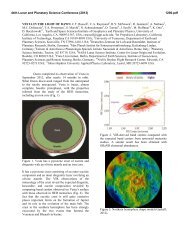
are at the present time (Figure 2.1-1). JSO will<br />
address these questions using a combination of<br />
approaches. First, the induced dipoles at<br />
Europa, Ganymede, <strong>and</strong> Callisto will be well<br />
characterized. Galileo obtained only the<br />
minimum number of flybys of Callisto needed<br />
to infer an inductive response, <strong>and</strong> additional<br />
flybys will greatly improve our underst<strong>and</strong>ing<br />
of the strength, orientation, <strong>and</strong> time<br />
variability of the inferred dipole. Once in orbit<br />
around Ganymede, JSO will distinguish<br />
between an induced dipole <strong>and</strong> an intrinsic<br />
quadrupole. High-resolution spatial <strong>and</strong><br />
temporal magnetic sounding will allow<br />
inferences on the thickness <strong>and</strong> depth of an<br />
ocean <strong>and</strong> whether it is global. As a second<br />
line of investigation, JSO will measure the<br />
gravitational <strong>and</strong> topographic response to the<br />
time-variable tidal potential (i.e., measure the<br />
second degree Love numbers k2 <strong>and</strong> h2). With
01 NOVEMBER 2007 2007 JUPITER SYSTEM OBSERVER MISSION STUDY: FINAL REPORT<br />
SECTION 2— JUPITER SYSTEM SCIENCE GOALS AND OBJECTIVES Task Order #NMO710851<br />
Figure 2.1-1. Interior structure of Galilean<br />
satellites (from Schubert et al., 2006).<br />
oceans, the amplitude of the time-variable<br />
tides on Europa, Ganymede, <strong>and</strong> Callisto are<br />
~30, 7, <strong>and</strong> 5 m; without oceans, these<br />
amplitudes decrease by a factor of 10–30. A<br />
grounded ice layer (i.e., non-global ocean) will<br />
have a complex tidal response that may be<br />
measurable for each icy satellite. Gravity data<br />
returned from JSO will also help to elucidate<br />
questions about the internal mass distribution<br />
of the three icy satellites, their degree of<br />
differentiation, <strong>and</strong> whether they are in<br />
hydrostatic equilibrium. During orbit around<br />
Ganymede, JSO will obtain high-order<br />
gravitational harmonics that will enable better<br />
mapping of the magnitude <strong>and</strong> distribution of<br />
small-scale gravity anomalies. <strong>Final</strong>ly, JSO<br />
will conduct subsurface active (radar)<br />
sounding through flybys of Europa <strong>and</strong><br />
Callisto, <strong>and</strong> from orbit around Ganymede;<br />
current estimates suggest that radar can<br />
penetrate ~10 km into a relatively clean,<br />
unfractured ice shell.<br />
High-resolution imaging will locate surface<br />
features on the satellites with the accuracy<br />
needed to address outst<strong>and</strong>ing issues regarding<br />
their rotational <strong>and</strong> orbital states, such as<br />
whether they are rotating nonsynchronously,<br />
their obliquities <strong>and</strong> inclinations <strong>and</strong> whether<br />
these change over year-long timescales, <strong>and</strong><br />
for Ganymede, the libration amplitude. These<br />
data will help answer questions such as<br />
whether libration <strong>and</strong>/or nonzero obliquity<br />
contributes to tidal heating, <strong>and</strong> whether the<br />
satellites are moving toward or away from<br />
2-2<br />
<strong>Jupiter</strong>. In addition, JSO will make<br />
measurements of the heat flow from the<br />
satellites at many geometries relative to the<br />
Sun, using thermal-IR (10–30 micron)<br />
measurements, determine whether “hot spots”<br />
exist on Europa <strong>and</strong> Ganymede, <strong>and</strong> monitor<br />
Io’s volcanism.<br />
After several visits by spacecraft <strong>and</strong><br />
decades of Earth-based observing, motivation<br />
for continued intensive study of <strong>Jupiter</strong>’s<br />
atmosphere by remote sensing lies in the<br />
interconnected nature of all of its physical <strong>and</strong><br />
chemical processes <strong>and</strong> the lessons they hold<br />
for the behavior of planetary atmospheres<br />
generally. <strong>Jupiter</strong> is a vast laboratory of interrelated<br />
electromagnetic phenomena,<br />
geophysical fluid flow <strong>and</strong> chemistry. The<br />
difficulties faced by previous spacecraft<br />
investigations has been in their brevity (flybys<br />
by Pioneers 10 <strong>and</strong> 11, Voyagers 1 <strong>and</strong> 2,<br />
Ulysses, Cassini, <strong>and</strong> New Horizons),<br />
b<strong>and</strong>width-imposed limits on spatial coverage<br />
(Galileo), <strong>and</strong> limitations on spatial resolution<br />
<strong>and</strong> continuity (Earth-based observations).<br />
Because of these restrictions, no mission yet<br />
flown has obtained the long-term, highresolution<br />
climate database necessary for truly<br />
underst<strong>and</strong>ing <strong>Jupiter</strong>’s atmosphere. The Juno<br />
mission, scheduled to fly before JSO, will<br />
provide crucial information on the spatial<br />
variation of the deep water <strong>and</strong> ammonia<br />
abundances, structure of the magnetic field,<br />
<strong>and</strong> the depth of the jet streams, but it will be<br />
unable to monitor the upper troposphere <strong>and</strong><br />
stratosphere in sufficient detail to determine<br />
the crucial transport mechanisms for heat,<br />
momentum, <strong>and</strong> condensable vapors that (for<br />
example) determine the structure of the jet<br />
streams in the atmosphere. In effect, JSO will<br />
constitute the first long-term climate sounder<br />
for <strong>Jupiter</strong>’s upper troposphere <strong>and</strong><br />
stratosphere. A primary goal of the JSO<br />
mission will be to provide a broad-based set of<br />
synoptic observations of these various<br />
atmospheric phenomena over substantial<br />
portions of <strong>Jupiter</strong>’s seasonal <strong>and</strong> non-seasonal<br />
cycles, with extensive spatial coverage,<br />
thereby providing a dataset similar to those<br />
used to establish a fundamental climatology<br />
for the Earth, Mars <strong>and</strong> Venus. These data will<br />
provide powerful constraints on the<br />
organization of weather on <strong>Jupiter</strong>, the<br />
structure of the atmosphere near <strong>and</strong> above the
2007 JUPITER SYSTEM OBSERVER MISSION STUDY: FINAL REPORT 01 NOVEMBER 2007<br />
Task Order #NMO710851 SECTION 2— JUPITER SYSTEM SCIENCE GOALS AND OBJECTIVES<br />
clouds, the processes that pump <strong>Jupiter</strong>’s jet<br />
streams, <strong>and</strong> the flow of energy <strong>and</strong> trace<br />
constituents among vortices, jets, <strong>and</strong> waves,<br />
thus revolutionizing our underst<strong>and</strong>ing of<br />
<strong>Jupiter</strong>’s stratosphere.<br />
Likewise, the JSO mission will enable longterm<br />
monitoring of Io’s hyperactive<br />
volcanism. High-resolution observations over<br />
various timescales will reveal the physical<br />
constraints that contribute to the different<br />
eruption styles of plumes, the compositions of<br />
lava flows <strong>and</strong> plains materials, <strong>and</strong> elucidate<br />
the ambiguous relationships between paterae<br />
<strong>and</strong> mountains. The combination of close<br />
flybys <strong>and</strong> distant monitoring over several<br />
years will provide invaluable insight into Io’s<br />
volcanic <strong>and</strong> tectonic processes.<br />
The JSO mission presents an opportunity to<br />
study the <strong>Jupiter</strong> system <strong>and</strong> make<br />
unprecedented long-term, high-resolution<br />
observations of the Io torus, including its<br />
sources <strong>and</strong> wide-ranging effects on the<br />
system. Monitoring the torus is essential for<br />
investigating correlations between Io’s<br />
volcanic activity, loss of material from Io,<br />
<strong>Jupiter</strong>'s magnetospheric activity, <strong>and</strong> transport<br />
of material into the system as a whole.<br />
JSO will enable long-term, dedicated<br />
observations of <strong>Jupiter</strong>’s rings <strong>and</strong> their<br />
intriguing relationships to nearby small<br />
satellites. Imaging at many different phase<br />
angles <strong>and</strong> over a range of timescales will<br />
enable the rings to be fully characterized <strong>and</strong><br />
their composition <strong>and</strong> dynamics to be<br />
understood.<br />
Under the imperative of achieving the best<br />
overall <strong>Jupiter</strong> system science, we have<br />
identified a number of important <strong>and</strong><br />
discriminating science focus areas that provide<br />
the foundation for specific scientific goals.<br />
First, given that Ganymede is one of only three<br />
solid-surface bodies in the solar system to<br />
possess an internally generated magnetic field,<br />
it is necessary to:<br />
• Underst<strong>and</strong> the processes that give rise to<br />
the Ganymede internal magnetic field<br />
• Underst<strong>and</strong> Ganymede’s internal structure<br />
<strong>and</strong> mass distribution with emphasis on<br />
implications for an internal dynamo.<br />
Second, <strong>and</strong> within the context of these first<br />
two objectives <strong>and</strong> the overall system science,<br />
there is a priority to:<br />
2-3<br />
• Underst<strong>and</strong> the surface composition of the<br />
Galilean satellites, confirm the presence of<br />
potential subsurface oceans <strong>and</strong> provide a<br />
framework for relating the surface geology<br />
to interior processes.<br />
<strong>Final</strong>ly, as the <strong>Jupiter</strong> system may be an<br />
important analog for extra solar planetary<br />
systems, the JSO mission must lead to:<br />
• Underst<strong>and</strong>ing the dynamics <strong>and</strong> structure<br />
of the <strong>Jupiter</strong> atmosphere along with<br />
characterization of relations to the<br />
magnetosphere <strong>and</strong> how the components<br />
(large <strong>and</strong> small satellites, rings etc.) of this<br />
“miniature solar system” interact<br />
2.1.1 Science Traceability<br />
Results from the Galileo mission in the<br />
1990s generated the highly compelling<br />
hypothesis that a subsurface ocean is present at<br />
Europa <strong>and</strong> that liquid layers are most likely<br />
present within Ganymede <strong>and</strong> Callisto.<br />
Because of the implications for <strong>Jupiter</strong> system<br />
evolution <strong>and</strong> potential habitability, there has<br />
been consistent science community support for<br />
a return to the <strong>Jupiter</strong> system. Beginning with<br />
Europa Orbiter (EO), science drivers were<br />
codified to form a traceable basis for such a<br />
mission. Subsequently, the NASA<br />
commissioned “Solar <strong>System</strong> Decadal Survey”<br />
carried out under the auspices of the National<br />
Research Council (New Frontiers in the Solar<br />
<strong>System</strong>: An Integrated Exploration Strategy,<br />
2003) identified Europa as the top science<br />
priority for a large-scale mission. This report<br />
also stressed the importance of <strong>Jupiter</strong>, its<br />
rings <strong>and</strong> the magnetosphere environment,<br />
along with all of the Galilean satellites to<br />
underst<strong>and</strong>ing the system as a whole. The<br />
overall system science objectives for the<br />
<strong>Jupiter</strong> system led NASA to initiate the <strong>Jupiter</strong><br />
Icy Moons Orbiter (JIMO) mission. The JIMO<br />
Science Definition Team (SDT) generated a<br />
comprehensive set of science goals, objectives,<br />
investigations <strong>and</strong> measurements (Greeley et<br />
al., 2004a). Although the JIMO mission was<br />
indefinitely deferred, the work of the SDT for<br />
that mission provides the foundation to the<br />
JSO concept discussed here. Much of the<br />
cumulative science knowledge of the <strong>Jupiter</strong><br />
system extending beyond the Decadal <strong>and</strong><br />
JIMO studies with later Galileo Orbiter <strong>and</strong><br />
Cassini flyby observations is discussed in<br />
chapters of the book <strong>Jupiter</strong> - The Planet,
01 NOVEMBER 2007 2007 JUPITER SYSTEM OBSERVER MISSION STUDY: FINAL REPORT<br />
SECTION 2— JUPITER SYSTEM SCIENCE GOALS AND OBJECTIVES Task Order #NMO710851<br />
Satellites <strong>and</strong> Magnetosphere (Bagenal et al.,<br />
2004).<br />
2.1.2 JSO SDT Science Strategy <strong>and</strong> Structure<br />
The Jovian system provides a unique<br />
laboratory to study, in a single place, diverse<br />
<strong>and</strong> dynamic planetary processes. The<br />
discovery of extra-solar planetary systems<br />
with <strong>Jupiter</strong>-sized bodies has led to a<br />
revolution in thought regarding how these<br />
systems form <strong>and</strong> evolve. The scientific<br />
exploration of <strong>Jupiter</strong> <strong>and</strong> its diverse set of<br />
satellites provide a basis for improving our<br />
underst<strong>and</strong>ing of dynamical behavior, satellite<br />
interactions <strong>and</strong> geologic events throughout<br />
Solar <strong>System</strong> history. For example, the icy<br />
Galilean satellites afford a window into Solar<br />
<strong>System</strong> history by preserving in their cratering<br />
records a chronology dating back nearly 4.5<br />
billion years <strong>and</strong> extending to the present. The<br />
continuously erupting volcanoes of Io may<br />
derive from an interior magma ocean <strong>and</strong>,<br />
thus, studying Io can provide insight into<br />
magma oceans that may have been present<br />
within the early Earth <strong>and</strong> Moon. Ganymede’s<br />
rare internally-generated magnetic field is an<br />
important example of how dynamos work. The<br />
confirmation <strong>and</strong> characterization of icy<br />
satellite subsurface oceans will impact<br />
considerations of habitability. Characterizing<br />
2-4<br />
the dynamics <strong>and</strong> temperature structure of<br />
<strong>Jupiter</strong>’s atmosphere will illuminate the<br />
mechanisms by which tides on <strong>Jupiter</strong> transfer<br />
<strong>Jupiter</strong>’s rotational energy to the Galilean<br />
satellites <strong>and</strong> thereby, via the Laplace<br />
resonance, drive the satellites’ extensive<br />
tectonism <strong>and</strong> volcanism. Underst<strong>and</strong>ing the<br />
composition <strong>and</strong> volatile inventory of <strong>Jupiter</strong><br />
will shed light into how planets accrete from<br />
solar nebulae. <strong>Final</strong>ly, like our Sun, <strong>Jupiter</strong><br />
influences its system through its extensive<br />
magnetic field. Taking advantage of this<br />
natural laboratory with JSO will advance<br />
scientific underst<strong>and</strong>ing with the unifying<br />
theme: Probing the Foundations of Planetary<br />
<strong>System</strong>s.<br />
To address the broad range of Jovian<br />
system science questions, the JSO SDT<br />
divided itself into four focused theme groups,<br />
(1) Jovian Atmosphere, (2) Magnetospheres<br />
(3) Satellites <strong>and</strong> (4) Interiors. Guiding the<br />
overall process were the “Solar <strong>System</strong><br />
Decadal Survey,” the subsequent NASA<br />
Roadmaps, <strong>and</strong> the Outer Planets Assessment<br />
Group (OPAG) “Scientific Goals <strong>and</strong><br />
Pathways for Exploration of the Outer Solar<br />
<strong>System</strong>” document. The detailed traceability to<br />
the Decadal Survey is provided in Appendix<br />
C. Specific key elements are summarized in<br />
Table 2.1-1. These are grouped, <strong>and</strong><br />
Table 2.1-1. Traceability of JSO Science to Major Themes <strong>and</strong> Governing Documents<br />
High-level Science Solar <strong>System</strong> Exploration ("Decadal") 2006 SSE Roadmap <strong>and</strong><br />
Focus<br />
Survey<br />
2007 NASA Science Plan<br />
Learn how the Sun's retinue of planets How did the Sun's Family of planets <strong>and</strong><br />
originated <strong>and</strong> evolved<br />
Discover how the basic laws of physics<br />
<strong>and</strong> chemistry, acting over aeons, can<br />
lead to the diverse phenomena<br />
observed in complex systems, such as<br />
minor bodies originate?<br />
planets<br />
How did the solar system evolve to its<br />
Underst<strong>and</strong> how physical <strong>and</strong> chemical<br />
processes determine the main<br />
characteristics of the planets <strong>and</strong> their<br />
environments, thereby illuminating the<br />
workings of the Earth.<br />
current diverse state?<br />
Determine how life developed in the What are the characteristics of the solar<br />
solar system, where it may coexist, system that lead to the origin of life?<br />
whether extant life forms exist beyond How did life begin <strong>and</strong> evolve on Earth<br />
Earth <strong>and</strong> in what ways life modifies<br />
planetary environments<br />
<strong>and</strong> has it evolved elsewhere in the<br />
solar system<br />
Physical Processes<br />
Potential for<br />
Habitability<br />
Environment<br />
Explore the terrestrial space<br />
environment to discover what potential<br />
hazards to Earth's biosphere may exist<br />
What are the hazards <strong>and</strong> resources in<br />
the solar system environment that will<br />
affect the extension of human presence<br />
in space<br />
JSO Science Theme<br />
Satellites<br />
Interiors<br />
Atmosphere<br />
Magnetospheres<br />
Satellites<br />
Interiors<br />
Magnetospheres<br />
Satellites
2007 JUPITER SYSTEM OBSERVER MISSION STUDY: FINAL REPORT 01 NOVEMBER 2007<br />
Task Order #NMO710851 SECTION 2— JUPITER SYSTEM SCIENCE GOALS AND OBJECTIVES<br />
paraphrased, from the Decadal Survey into<br />
three high-level traceable focus areas, Physical<br />
Processes, Potential for Habitability, <strong>and</strong><br />
Environment.<br />
2.2 Science Background, Goals, <strong>and</strong><br />
Objectives<br />
Each JSO SDT science theme group<br />
compiled a comprehensive set of Goals,<br />
Objectives, Investigations <strong>and</strong> Measurements<br />
for studying the <strong>Jupiter</strong> system. The detailed<br />
science flow, including an assessment of<br />
science value, for each theme group is<br />
provided in Appendix C. Each group<br />
prioritized their Objectives <strong>and</strong> Investigations.<br />
Within the Satellites group, each target was<br />
prioritized separately. Because there are over<br />
300 measurements, a summary version that<br />
focuses on key elements is provided in<br />
Foldout 1 (FO-1: Note that the colors used in<br />
this foldout provide a one-to-one mapping<br />
with the detailed Goals, Objectives,<br />
Investigations <strong>and</strong> Measurements in Appendix<br />
C). Many instruments were considered for the<br />
notional payload, but the ones that were<br />
selected were chosen based on their ability to<br />
meet multiple science goals, <strong>and</strong> therefore<br />
achieve maximum synergy among different<br />
science investigations.<br />
The remainder of this section provides a<br />
detailed discussion, by theme, of the science to<br />
be accomplished by JSO. This discussion<br />
deviates somewhat from the overall SDT<br />
analysis structure. Specifically, the Satellites<br />
<strong>and</strong> Interiors groups have been combined.<br />
Because of the different methods by which<br />
satellite surface science <strong>and</strong> interior<br />
geophysics are studied, it was decided to<br />
initially keep them separate in defining<br />
measurements, investigations, etc. Of course,<br />
interior processes are intimately linked to<br />
surface composition, geology, tectonics <strong>and</strong><br />
morphology <strong>and</strong>, thus, we have combined<br />
them in the discussion that follows.<br />
2.2.1 The Jovian Atmosphere<br />
2.2.1.1 Background<br />
Much is known about <strong>Jupiter</strong>’s atmosphere<br />
from remote-sensing observations acquired by<br />
the Pioneer, Voyager, Hubble, Galileo, Cassini<br />
<strong>and</strong> New Horizons missions. Their remotesensing<br />
observations of the atmosphere have<br />
been complemented recently by Earth-based<br />
measurements taking advantage of major<br />
2-5<br />
advances in the capabilities of modern<br />
telescopes <strong>and</strong> associated instrumentation. In<br />
addition, the experiments associated with the<br />
Galileo mission’s direct probe into <strong>Jupiter</strong>’s<br />
atmosphere provided a major advance in our<br />
underst<strong>and</strong>ing of the structure, composition<br />
<strong>and</strong> dynamics of the atmosphere.<br />
Unfortunately, it entered a region that is<br />
considered to be anomalously dry with a<br />
minimum of cloud opacity (Orton et al., 1996),<br />
<strong>and</strong> several of its results—particularly for<br />
volatiles such as NH3, H2O <strong>and</strong> associated<br />
cloud layers—are not considered<br />
representative of the planet as a whole. Most<br />
of these results have been summarized by<br />
Young (2003), Taylor et al. (2004), West et al.<br />
(2004), Ingersoll et al. (2004), Moses et al.<br />
(2004), Harrington et al. (2004), Yelle <strong>and</strong><br />
Miller (2004), <strong>and</strong> Vasavada <strong>and</strong> Showman<br />
(2005).<br />
In 2016, the Juno mission is scheduled to<br />
begin microwave remote-sensing <strong>and</strong><br />
gravitational mapping of <strong>Jupiter</strong>’s deep<br />
atmosphere, results that can be linked to Earthbased<br />
observations using the JSO instruments.<br />
Nonetheless, many questions will remain after<br />
Juno about the overlying atmosphere. Juno<br />
will greatly boost our underst<strong>and</strong>ing of the<br />
depth of the jet streams, the small-scale<br />
structure of <strong>Jupiter</strong>’s magnetic field, <strong>and</strong> the<br />
deep abundance of water vapor. However, in<br />
mapping the upper troposphere <strong>and</strong><br />
stratosphere, Juno will have neither sufficient<br />
spatial resolution, wavelength coverage, nor<br />
temporal coverage to constrain the small-scale<br />
turbulent processes that transport momentum,<br />
heat, <strong>and</strong> tracers <strong>and</strong> that are therefore crucial<br />
in setting the basic structure of the jets, clouds,<br />
belts, zones, <strong>and</strong> vortices. JSO will provide the<br />
first high-resolution, broad-wavelength climate<br />
database that will have global coverage over a<br />
long-temporal baseline. For example, it<br />
remains unclear whether <strong>Jupiter</strong>’s meteorology<br />
is primarily powered by deep convection or<br />
cloud-layer processes (e.g., thunderstorms,<br />
baroclinic instabilities, <strong>and</strong> other cloud-layer<br />
circulations), whether latent heat of water or<br />
hydrogen ortho-para conversion play a role in<br />
driving the circulation, or whether vertical<br />
waves are the principal source of energy<br />
driving the unexpectedly warm thermosphere<br />
temperature. We know little about the details
01 NOVEMBER 2007 2007 JUPITER SYSTEM OBSERVER MISSION STUDY: FINAL REPORT<br />
SECTION 2—JUPITER SYSTEM SCIENCE GOALS AND OBJECTIVES Task Order #NMO710851 SCIENCE TRACEABILITY MATRIX<br />
SCIENCE<br />
THEME GOALS OBJECTIVES INVESTIGATIONS Magnetometer<br />
<strong>Jupiter</strong> Atmosphere<br />
Magnetosphere<br />
<strong>Study</strong> the composition, structure, chemistry, <strong>and</strong> dynamics of <strong>Jupiter</strong>’s atmosphere <strong>Study</strong> atmospheric dynamics at scales ranging from less than one scale height to the planetary scale; <strong>Study</strong> the temperature <strong>and</strong><br />
energy balance of the planet to improve our underst<strong>and</strong>ing of the relative roles of radiative solar radiative heating, winds <strong>and</strong> eddies in<br />
driving atmospheric circulation <strong>and</strong> convection; <strong>Study</strong> <strong>Jupiter</strong>'s clouds <strong>and</strong> hazes; <strong>Study</strong> the composition <strong>and</strong> chemistry of <strong>Jupiter</strong>’s<br />
atmosphere to underst<strong>and</strong> sources <strong>and</strong> sinks, <strong>and</strong> dynamics from disequilibrium species; <strong>Study</strong> the auroral emissions <strong>and</strong> dynamic<br />
effects of the magnetosphere on the upper atmosphere<br />
<strong>Study</strong> the structure <strong>and</strong> dynamics of the Jovian magnetosphere, including Determine the coupling of magnetosphere/ionosphere/atmosphere<br />
processes that generate <strong>Jupiter</strong>’s aurora<br />
2-6<br />
INSTRUMENT TYPE<br />
Plasma EPD<br />
PWS<br />
HIC<br />
UV Imager<br />
UV Imaging<br />
Spectrometer<br />
UV<br />
Hyperspectral<br />
Imager<br />
UV<br />
Spectrometer<br />
FUV Imaging<br />
Spectrometer<br />
Med-Res<br />
Imager<br />
Hi-Res Visible<br />
Imager (color)<br />
Super Hi-Res<br />
Imager<br />
Stereo Imager<br />
VIS-NIR<br />
Hyperspectral<br />
Imager<br />
VIS-NIR<br />
Imaging<br />
Spectrometer<br />
Visible<br />
Spectrometer<br />
Visible<br />
Polarimeter<br />
IR Imager<br />
IR Imaging<br />
Spectrometer<br />
Mid-IR<br />
Spectrometer<br />
Far-IR Imaging<br />
Radiometer<br />
Thermal<br />
Imaging<br />
Spectrometer<br />
Thermal Imager<br />
Thermal<br />
Hyperspectral<br />
Imager<br />
Radio<br />
X-ray Imager<br />
Sub-millimeter<br />
Sounder<br />
Microwave<br />
Radiometer<br />
LIDAR<br />
X X X X X X X X X X X X X X X<br />
X X X X<br />
Characterize the spatial distribution <strong>and</strong> temporal variability of minor atmospheric<br />
Underst<strong>and</strong> the species to underst<strong>and</strong> <strong>Jupiter</strong>'s origin <strong>and</strong> present state<br />
Characterize <strong>Jupiter</strong>'s clouds <strong>and</strong> hazes <strong>and</strong> the processes that maintain them processes that maintain<br />
the composition, Underst<strong>and</strong> the processes that maintain the hot thermosphere<br />
structure <strong>and</strong> dynamics<br />
Determine the bulk abundance of water in the deep atmosphere; Determine the 3-D concentrations of the condensable gases water<br />
<strong>and</strong> ammonia <strong>and</strong> disequilibrium species<br />
Determine the height, composition, optical thickness, <strong>and</strong> particle size distribution of clouds <strong>and</strong> hazes; Determine the concentrations<br />
of condensable atmospheric gases<br />
Characterize the vertical structure of the thermosphere <strong>and</strong> its spatial <strong>and</strong> temporal variability; Determine the properties <strong>and</strong> fluxes of<br />
vertically propagating waves; Characterize the atmosphere-magnetosphere interaction, including the contribution of aurorae to the<br />
X<br />
X<br />
X<br />
X<br />
X<br />
X<br />
X<br />
X<br />
X<br />
X X<br />
X<br />
X X<br />
X<br />
X<br />
X X<br />
X<br />
X<br />
X<br />
X<br />
of the Jovian<br />
thermal structure of the upper atmosphere; Determine the latitudinal variation of solar-energy absorption <strong>and</strong> thermal radiation<br />
atmosphere as a Type <strong>Study</strong> the temperature <strong>and</strong> energy balance of the planet to improve our<br />
underst<strong>and</strong>ing of the relative roles of internal <strong>and</strong> solar heating in controlling the<br />
Example of a Gas Giant structure <strong>and</strong> dynamics of the atmosphere<br />
Planet<br />
Determine the processes that maintain the jet streams, polar vortex circulations,<br />
Determine the global, 3-D temperature structure from the thermosphere to the upper troposphere; Determine the dynamical<br />
contributions to the latitudinal energy transport<br />
Determine the wind speeds, temperatures, <strong>and</strong> variability of atmospheric features; Determine the latitudinal momentum <strong>and</strong> heat<br />
X X X X X<br />
large vortices, quasi-quadrennial oscillation, <strong>and</strong> planetary-scale waves such as<br />
the hot spots, equatorial plumes, <strong>and</strong> slowly moving thermal features<br />
fluxes of waves <strong>and</strong> eddies; Characterize the existence, horizontal wavelengths, <strong>and</strong> speeds of small-scale atmospheric waves to<br />
constrain the vertical stability structure (Brunt-Vaisala frequency) of the upper troposphere; Determine the concentrations of<br />
condensable atmospheric gases<br />
X X X X X X X X<br />
Characterize the morphology, spatial distribution, <strong>and</strong> role of thunderstorms <strong>and</strong> Determine the occurrence frequency, locations, pressures, <strong>and</strong> temporal evolution of thunderstorms; Determine the occurrence<br />
small-scale waves <strong>and</strong> eddies in driving the large-scale circulation<br />
frequency, locations, amplitude, spectrum, <strong>and</strong> depth of lightning; Determine the latitudinal momentum <strong>and</strong> heat fluxes of waves <strong>and</strong><br />
eddies<br />
X X X X X X X<br />
Underst<strong>and</strong> the structure <strong>and</strong> circulation of the middle <strong>and</strong> upper atmosphere Determine the global, 3-D temperature structure, radiative heating rates, <strong>and</strong> wind speeds from the thermosphere to the upper<br />
troposphere<br />
X X X X<br />
Establish internal structure of icy moons including presence <strong>and</strong> properties of Investigate <strong>and</strong> confirm presence of a conducting layer at Ganymede <strong>and</strong> deeper conducting layers by monitoring steady <strong>and</strong> time-<br />
putative conducting layers, measurement of higher harmonics <strong>and</strong> secular varying magnetic configurations; Investigate response of local magnetospheric plasma, energetic particle, <strong>and</strong> ionospheric<br />
variations of Ganymede's magnetic field <strong>and</strong> set limits on intrinsic magnetic fields<br />
for Europa <strong>and</strong> Callisto<br />
environment at Ganymede to changing total <strong>and</strong> induced magnetic fields; Investigate <strong>and</strong> confirm presence of a conducting layer at<br />
Europa <strong>and</strong> Callisto <strong>and</strong> deeper conducting layers by monitoring steady <strong>and</strong> time-varying magnetic configurations; Investigate<br />
response of local magnetospheric plasma, energetic particle <strong>and</strong> ionospheric environment at Europa <strong>and</strong> Callisto to changing<br />
magnetic fields.<br />
X X<br />
Investigate the magnetic field, particle populations, <strong>and</strong> dynamics of Ganymede's Investigate the magnetopause to establish spatial distribution of reconnecting field lines <strong>and</strong> to characterize the spatial distribution <strong>and</strong><br />
magnetosphere.<br />
temporal distribution of reconnection, including possible intermittency of reconnection; Investigate Ganymede's magnetospheric<br />
structure, in particular the spatial structure <strong>and</strong> energy distributions of particle populations, including time variability in response to<br />
external Jovian magnetospheric perturbations; Investigate the generation of Ganymede's aurora; Investigate the modification of<br />
X X X X X X X<br />
Underst<strong>and</strong> the<br />
surface composition <strong>and</strong> structure on open vs. closed field line regions.<br />
magnetospheric Determine the effect of the Jovian magnetosphere on the icy moons. Underst<strong>and</strong> Investigate the magnetic field, plasma, energetic particle, electromagnetic, <strong>and</strong> dust distribution in the Jovian magnetosphere, at the<br />
effects of the moons on the magnetosphere <strong>and</strong> <strong>Jupiter</strong>'s auroral ionosphere.<br />
environments of <strong>Jupiter</strong>,<br />
its moons <strong>and</strong> their<br />
interactions<br />
jovicentric orbits of the moons, including spatial <strong>and</strong> temporal variations; Investigate the changes of magnetospheric properties (the<br />
magnetic field, plasma, energetic particle, electromagnetic, <strong>and</strong> dust environments) in the near vicinity of the moons in order to<br />
establish effects of the magnetosphere on the moons <strong>and</strong> to characterize the moons as sources of gas <strong>and</strong> dust tori. Investigate<br />
effects of direct magnetospheric plasma, energetic particle, solar UV, <strong>and</strong> interplanetary dust interactions with the moon surfaces &<br />
atmospheres, <strong>and</strong> associated temporal variations; Investigate the coupling of the moons with the low altitude magnetosphere <strong>and</strong> the<br />
Jovian atmosphere, including formation processes of the satellite footprint <strong>and</strong> wake aurora in the Jovian polar atmosphere to<br />
underst<strong>and</strong> the electrodynamic circuit connecting them<br />
X X X X X X X<br />
Underst<strong>and</strong> the contributions of Io to the composition, <strong>and</strong> to the transient <strong>and</strong><br />
periodic dynamics, of the Jovian magnetosphere<br />
Investigate the relationship between temporal variations of volcanic activity on Io, the Io torus <strong>and</strong> the magnetosphere; Determine the<br />
composition of the plasma torus <strong>and</strong> iogenic neutrals.<br />
X X X<br />
<strong>Study</strong> the global dynamics of the Jovian magnetosphere including processes that Identify locations <strong>and</strong> activity levels for sources of major <strong>and</strong> minor plasma ions; Investigate internal transport acceleration <strong>and</strong> loss<br />
generate the planetary aurora. Identify internal particle sources, acceleration processes that shape <strong>and</strong> drive the Jovian magnetosphere <strong>and</strong> produce observed local time asymmetries; Investigate the<br />
processes, transport <strong>and</strong> loss processes that shape <strong>and</strong> drive the Jovian phenomenon of energetic particle injection in the inner magnetosphere; Investigate magnetospheric <strong>and</strong> solar wind energy sources X X X X X X<br />
magnetosphere. Underst<strong>and</strong> injection events in the inner magnetosphere. <strong>and</strong> dynamics for the <strong>Jupiter</strong> planetary aurora; Investigate the important boundary layers of the magnetosphere (Bow shock,<br />
magnetopause, plasma sheet boundary layer, high energy particle radiation belt boundaries, equatorial plasma disk)<br />
Io-Underst<strong>and</strong> heat balance, tidal dissipation, relationship to volcanism, <strong>and</strong> the<br />
coupling of its thermal/orbital evolution to that of the icy satellites<br />
I-Determine regional <strong>and</strong> global heat flow; I-Determine regional <strong>and</strong> global time-varying topography/shape<br />
X X<br />
Io-Monitor Io's active volcanism for insight into its geological history <strong>and</strong> evolution, I-Perform long-term <strong>and</strong> high-temporal-resolution monitoring of volcanic activity; I-Determine global distribution of volcanic activity <strong>and</strong><br />
<strong>and</strong> the mechanisms of surface changes<br />
styles; I-Characterize crustal recycling of volatiles; I-Determine eruption temperatures (implications for superheating); I-Determine<br />
X X X X X X<br />
Underst<strong>and</strong> the<br />
local, regional, <strong>and</strong> global topography<br />
Io-Underst<strong>and</strong> Io's surface geology, including the relationships between volcanism I-Determine distribution of geologic structures; I-Characterize distribution <strong>and</strong> transport of volatiles; I-Determine regional <strong>and</strong> global<br />
mechanisms responsible<br />
<strong>and</strong> tectonism, erosion <strong>and</strong> deposition processes<br />
topography; I-Characterize morphology <strong>and</strong> structure of geologic features; I-Perform surface monitoring for change detection<br />
for formation of surface Europa--Underst<strong>and</strong> geologic history, potential for current activity, <strong>and</strong> the E-Determine distribution of geologic structures; E-Determine differences in crater morphology <strong>and</strong> cratering rates over time <strong>and</strong><br />
features <strong>and</strong> implications for <strong>Jupiter</strong>'s satellite system<br />
between satellites; E-Constrain past non-synchronous rotation; E-Search for evidence of current activity through surface monitoring<br />
X<br />
X<br />
X<br />
X<br />
X<br />
X<br />
X X X<br />
X<br />
implications for<br />
for change detection, thermal anomalies, plumes<br />
geological history, Europa--Underst<strong>and</strong> heat balance <strong>and</strong> tidal dissipation E-Determine regional <strong>and</strong> global heat flow; E-Determine regional <strong>and</strong> global time-varying topography/shape X X X<br />
Europa--Underst<strong>and</strong> the processes responsible for the observed geologic features E-Characterize morphology <strong>and</strong> structure of geologic features; E-Underst<strong>and</strong> compositional variations <strong>and</strong> role in formation<br />
evolution, <strong>and</strong> levels of<br />
<strong>and</strong> as analogs for surface geology of other icy satellites<br />
mechanisms; E-Determine regional <strong>and</strong> global topography <strong>and</strong> relationship to surface features; E-Determine the role of regolith<br />
current activity<br />
formation <strong>and</strong> mass wasting in the modification of surface features<br />
X X X X X X<br />
Europa--Search for evidence of recent activity (e.g., thermal anomalies; the E-Search for changes in surface heat flowby mapping regolith thermal <strong>and</strong> thermophysical properties, <strong>and</strong> performing long-term<br />
presence of short-lived species; the absence of radiolytic products such as H2O2; monitoring of changes; E-Identify <strong>and</strong> map accumulation of radiation products <strong>and</strong> compounds which are unstable to radiation;<br />
X X X X X<br />
chemical disequilibrium).<br />
Monitor long-term changes in abundances of these materials<br />
Europa--Characterize suitability of surface for future l<strong>and</strong>er missions E-Evaluate surface structure, characteristics <strong>and</strong> properties at local scales (spatial scales of centimeters) X X<br />
Satellites<br />
FOLDOUT 1 (1 of 2)<br />
Laser Altimeter<br />
Ice Penetrating<br />
Radar<br />
SAR
01 NOVEMBER 2007 2007 JUPITER SYSTEM OBSERVER MISSION STUDY: FINAL REPORT<br />
SECTION 2—JUPITER SYSTEM SCIENCE GOALS AND OBJECTIVES Task Order #NMO710851 SCIENCE TRACEABILITY MATRIX<br />
SCIENCE<br />
THEME GOALS OBJECTIVES INVESTIGATIONS Magnetometer<br />
Satellites (continued)<br />
Interiors<br />
2-7<br />
INSTRUMENT TYPE<br />
FOLDOUT 1 (2 of 2)<br />
Plasma EPD<br />
PWS<br />
HIC<br />
UV Imager<br />
UV Imaging<br />
Spectrometer<br />
UV<br />
Hyperspectral<br />
Imager<br />
UV<br />
Spectrometer<br />
FUV Imaging<br />
Spectrometer<br />
Med-Res<br />
Imager<br />
Hi-Res Visible<br />
Imager (color)<br />
Super Hi-Res<br />
Imager<br />
Stereo Imager<br />
VIS-NIR<br />
Hyperspectral<br />
Imager<br />
VIS-NIR<br />
Imaging<br />
Spectrometer<br />
Visible<br />
Spectrometer<br />
Visible<br />
Polarimeter<br />
IR Imager<br />
IR Imaging<br />
Spectrometer<br />
Mid-IR<br />
Spectrometer<br />
Far-IR Imaging<br />
Radiometer<br />
Thermal<br />
Imaging<br />
Spectrometer<br />
Thermal Imager<br />
Thermal<br />
Hyperspectral<br />
Imager<br />
Radio<br />
X-ray Imager<br />
Sub-millimeter<br />
Sounder<br />
Microwave<br />
Radiometer<br />
LIDAR<br />
Ganymede--Underst<strong>and</strong> geologic history, potential for current activity, <strong>and</strong> the<br />
Underst<strong>and</strong> the implications for <strong>Jupiter</strong>'s satellite system<br />
mechanisms responsible<br />
G-Determine distribution of geologic structures; G-Determine differences in crater morphology <strong>and</strong> cratering rates over time <strong>and</strong><br />
between satellites; G-Constrain whether non-synchronous rotation has occurred in the past; G-Search for evidence of current activity<br />
through surface monitoring for change detection, thermal anomalies, plumes<br />
X X X X X X X<br />
for formation of surface Ganymede--Underst<strong>and</strong> the processes responsible for the observed geologic G-Characterize morphology <strong>and</strong> structure of geologic features; G-Determine regional <strong>and</strong> global topography <strong>and</strong> relationship to<br />
features <strong>and</strong> features<br />
surface features; G-Underst<strong>and</strong> compositional variations <strong>and</strong> role in formation mechanisms; G-Determine the role of regolith formation<br />
<strong>and</strong> mass wasting in the modification of surface features<br />
implications for<br />
Ganymede--Underst<strong>and</strong> heat balance <strong>and</strong> tidal dissipation G-Determine regional <strong>and</strong> global time-varying topography/shape; G-Determine regional <strong>and</strong> global heat flow<br />
geological history, Callisto--Underst<strong>and</strong> geologic history <strong>and</strong> implications for <strong>Jupiter</strong>'s satellite system C-Determine differences in crater morphology <strong>and</strong> cratering rates over time <strong>and</strong> between satellites; C-Identify <strong>and</strong> map distribution of<br />
evolution, <strong>and</strong> levels of<br />
other geologic structures<br />
X X<br />
X<br />
X X<br />
X X X<br />
X<br />
X<br />
current activity Callisto--Underst<strong>and</strong> the processes responsible for the observed geologic features C-Characterize morphology <strong>and</strong> structure of geologic features; C-Determine the role of regolith formation <strong>and</strong> mass wasting in the<br />
(continued)<br />
modification of surface features; C-Determine regional <strong>and</strong> global topography <strong>and</strong> relationship to surface features; C-Underst<strong>and</strong><br />
compositional variations <strong>and</strong> role in formation mechanisms<br />
X X X X X<br />
Io-Underst<strong>and</strong> the volatile component of Io's crust <strong>and</strong> its behavior I-Characterize volatile cycle: document composition, physical state, distribution, <strong>and</strong> transport of surface volatiles; I-Determine roles<br />
<strong>and</strong> rates of sublimation, sputtering, <strong>and</strong> radiation darkening<br />
X X X<br />
Io-Underst<strong>and</strong> the silicate component of Io's crust I-Identify compositions (including the source(s) of the 1.0- <strong>and</strong> 3.915-µm b<strong>and</strong>s) <strong>and</strong> physical characteristics (e.g., particle size,<br />
porosity) of silicates; I-Determine distribution of silicates; I-Search for compositional variability among silicates<br />
X X<br />
Europa--Underst<strong>and</strong> composition, physical characteristics, distribution, <strong>and</strong> E-Identify bulk material compositions, grain size, porosity, crystallinity, <strong>and</strong> physical state; E-Map distributions of different materials,<br />
Determine the surface<br />
compositions <strong>and</strong><br />
implications for the<br />
origin, evolution <strong>and</strong><br />
evolution of surface materials<br />
Europa--Determine if <strong>and</strong> how material is interchanged between surface <strong>and</strong><br />
ocean<br />
including radiolytic materials (e.g. SOx, O3, H2O2, OH, O2), <strong>and</strong> document variability over a range of timescales; E-Determine origin<br />
<strong>and</strong> evolution of non-ice materials, including the role of geologic processes; E-Characterize volatile cycle: document composition,<br />
physical state, distribution, <strong>and</strong> transport of surface volatiles, e.g. sublimation<br />
E-Profiling of thermal, compositional, <strong>and</strong> structural horizons; E-Perform coordinated overlapping topographic, compositional, <strong>and</strong><br />
thermal measurements to assess diagnostic geologic <strong>and</strong> compositional interrelationships<br />
X<br />
X<br />
X X<br />
X X<br />
X<br />
X<br />
X<br />
X<br />
X<br />
X X<br />
transport of surface Ganymede--Underst<strong>and</strong> composition, physical characteristics, distribution, <strong>and</strong> G-Identify bulk material compositions, grain size, porosity, crystallinity, <strong>and</strong> physical state; G-Map distributions of different materials,<br />
materials<br />
evolution of surface materials<br />
including radiolytic materials (e.g. SOx, O3, H2O2, OH, O2), <strong>and</strong> document variability over a range of timescales; G-Determine origin<br />
<strong>and</strong> evolution of non-ice materials, including the role of geologic processes; G-Characterize volatile cycle: document composition,<br />
physical state, distribution, <strong>and</strong> transport of surface volatiles, e.g. sublimation<br />
X X X X<br />
Callisto--Underst<strong>and</strong> composition, physical characteristics, distribution, <strong>and</strong> C-Identify bulk material compositions, grain size, porosity, crystallinity, <strong>and</strong> physical state; C-Map distributions of different materials,<br />
evolution of surface materials<br />
including radiolytic materials (e.g. SOx, O3, H2O2, OH, O2), <strong>and</strong> document variability over a range of timescales; C-Determine origin<br />
<strong>and</strong> evolution of non-ice materials, including the role of geologic processes; C-Characterize volatile cycle: document composition,<br />
physical state, distribution, <strong>and</strong> transport of surface volatiles, e.g. sublimation<br />
X X X<br />
Io-Underst<strong>and</strong> the sources (volcanism, sublimation, surface sputtering) <strong>and</strong> sinks I-Determine column densities of atmospheric/plume species across the globe <strong>and</strong> document correlations with plumes, geologic<br />
(freezing out, plasma pickup/sputtering, thermal escape) of atmospheric<br />
components<br />
features <strong>and</strong> local albedo variations; I-Perform long-term <strong>and</strong> high-temporal-resolution monitoring of atmosphere, plumes, limb-glow,<br />
<strong>and</strong> equatorial spots; I-Monitor Io torus; I-Determine the composition, distribution <strong>and</strong> physical characteristics (grain-size, crystallinity)<br />
of volatile materials on the surface, including SO2 frost<br />
X X<br />
Io-Underst<strong>and</strong> the temporal, spatial, <strong>and</strong> compositional variability of the<br />
atmosphere<br />
I-Perform long-term <strong>and</strong> high-temporal-resolution monitoring; I-Determine column densities <strong>and</strong> compositions of atmospheric/plume<br />
species across the globe; I-Determine temperatures of gas in plumes <strong>and</strong> atmosphere<br />
X X X<br />
Europa--Underst<strong>and</strong> the sources (sublimation, surface sputtering) <strong>and</strong> sinks E-Determine column densities of atmospheric species across the globe; E-Perform long-term <strong>and</strong> high-temporal-resolution monitoring<br />
Determine the<br />
(freezing out, plasma pickup/sputtering, thermal escape) of atmospheric<br />
components<br />
of atmosphere in context of plasma bombardment <strong>and</strong> potential endogenic variations; E-Determine the composition, distribution <strong>and</strong><br />
physical characteristics (grain-size, crystallinity, physical state) of volatile materials on the surface; E-Investigate sputtering processes<br />
X X X X<br />
compositions, origins,<br />
at high latitudes as compared with lower latitudes<br />
<strong>and</strong> evolution of the<br />
atmosphere, including<br />
transport of material<br />
throughout the Jovian<br />
Europa--Underst<strong>and</strong> the temporal, spatial, <strong>and</strong> compositional variability of the<br />
atmosphere<br />
Ganymede--Underst<strong>and</strong> the sources (sublimation, surface sputtering) <strong>and</strong> sinks<br />
(freezing out, plasma pickup/sputtering, thermal escape) of atmospheric<br />
components<br />
E-Determine column densities, compositions <strong>and</strong> temperatures of atmospheric species across the globe<br />
G-Determine column densities of atmospheric species across the globe; G-Perform long-term <strong>and</strong> high-temporal-resolution monitoring<br />
of atmosphere in context of magnetospheric variations; G-Determine the composition, distribution <strong>and</strong> physical characteristics (grainsize,<br />
crystallinity, physical state) of volatile materials on the surface; G-Investigate sputtering processes at high latitudes as compared<br />
X X<br />
X X<br />
X<br />
system<br />
with lower latitudes<br />
Ganymede--Underst<strong>and</strong> the temporal, spatial, <strong>and</strong> compositional variability of the<br />
atmosphere<br />
G-Determine column densities, compositions <strong>and</strong> temperatures of atmospheric species across the globe<br />
X X<br />
Callisto--Underst<strong>and</strong> the sources (sublimation, surface sputtering) <strong>and</strong> sinks C-Determine column densities of atmospheric species across the globe; C-Perform long-term <strong>and</strong> high-temporal-resolution monitoring<br />
(freezing out, plasma pickup/sputtering, thermal escape) of atmospheric<br />
components<br />
of atmosphere in context of plasma bombardment variations; C-Determine the composition, distribution <strong>and</strong> physical characteristics<br />
(grain-size, crystallinity, physical state) of volatile materials on the surface; C-Investigate sputtering processes at high latitudes as<br />
compared with lower latitudes<br />
X X X<br />
Callisto--Underst<strong>and</strong> the temporal, spatial, <strong>and</strong> compositional variability of the<br />
atmosphere<br />
C-Determine column densities, compositions <strong>and</strong> temperatures of atmospheric species across the globe<br />
X X<br />
Determine how the Determine the structure <strong>and</strong> particle properties of the Jovian ring system Determine the size distribution in each ring component; Determine the 3-D structure Jovian ring system; Determine the composition of<br />
components of the<br />
Jovian system operate<br />
<strong>and</strong> interact<br />
the rings <strong>and</strong> embedded moons; Complete a comprehensive search for small inner moons of <strong>Jupiter</strong>, down to a size of 100 m<br />
X X X<br />
Determine the interior Characterize the formation & chemical evolution of the <strong>Jupiter</strong> system Place bounds on the orbital evolution of the satellites; Determine the sizes <strong>and</strong> states of the cores of the moons. X X X<br />
structures <strong>and</strong> Determine the presence <strong>and</strong> location of water within these moons.<br />
processes operating in<br />
the Galilean Satellites in Characterize the operation of magnetic dynamo processes in the Jovian system<br />
relation to the formation <strong>and</strong> their interaction with the surrounding magnetic field<br />
Determine the extent of differentiation of the three icy satellites; Establish the presence of oceans; Characterize the extent <strong>and</strong><br />
location of water (including brines) in 3D within Europa, Ganymede <strong>and</strong> Callisto; Determine the thickness of the ice layer for all Icy X<br />
Satellites<br />
Globally characterize Ganymede's intrinsic magnetic field <strong>and</strong> search for temporal variability in the field; Characterize the interaction of<br />
Ganymede's magnetosphere with <strong>Jupiter</strong>'s magnetosphere; Monitoring of <strong>Jupiter</strong>'s magnetic-field environment, with the goal of X X X X<br />
X X X X X<br />
<strong>and</strong> history of the <strong>Jupiter</strong><br />
searching for changes in the intrinsic Jovian field <strong>and</strong> characterizing plasma processes in the Jovian magnetosphere<br />
system <strong>and</strong> potential<br />
habitability of the<br />
moons.<br />
Identify the dynamical processes that cause internal evolution <strong>and</strong> near-surface<br />
tectonics of all four moons<br />
Determine the extent of differentiation of all four satellites; Characterize the near-surface tectonic <strong>and</strong> volcanic processes <strong>and</strong> their<br />
relation to interior processes<br />
X X X X X X X X X<br />
Laser Altimeter<br />
Ice Penetrating<br />
Radar<br />
SAR
01 NOVEMBER 2007 2007 JUPITER SYSTEM OBSERVER MISSION STUDY: FINAL REPORT<br />
SECTION 2— JUPITER SYSTEM SCIENCE GOALS AND OBJECTIVES Task Order #NMO710851<br />
of how trace constituents are distributed<br />
throughout <strong>Jupiter</strong>’s atmosphere, particularly<br />
in the stratosphere where there is a dearth of<br />
information on any details of its thermal<br />
structure, composition <strong>and</strong> circulation. Little is<br />
known about the thermal or compositional<br />
structure of the atmosphere at spatial scales<br />
below some 3000 km, which is the limit of<br />
large Earth-based telescopes in the midinfrared.<br />
2.2.1.2 Goals <strong>and</strong> Objectives<br />
High-resolution, long-term (multi-year)<br />
imaging of the clouds will revolutionize our<br />
underst<strong>and</strong>ing of <strong>Jupiter</strong>’s cloud-layer<br />
meteorology. JSO will yield unprecedented<br />
insight into key questions such as: What are<br />
the relative roles of deep convection <strong>and</strong><br />
cloud-layer turbulence in powering the jet<br />
streams that dominate <strong>Jupiter</strong>’s dynamics?<br />
What are the sources of cloud-layer<br />
turbulence—thunderstorms, baroclinic instabilities,<br />
or other processes, how do they vary<br />
in latitude <strong>and</strong> time, <strong>and</strong> what is their role in<br />
driving the circulation? Do small eddies pump<br />
momentum up-gradient into the jets, thereby<br />
helping to maintain the jets, as has been<br />
tentatively observed at some latitudes on both<br />
<strong>Jupiter</strong> <strong>and</strong> Saturn from Cassini data (Salyk et<br />
al., 2006; Del Genio et al., 2007)? How do<br />
compact vortices (of which the Great Red Spot<br />
<strong>and</strong> Ovals are but the largest examples)<br />
interact with the jets—do they contribute to jet<br />
pumping, or do they instead rob energy from<br />
the jets (Vasavada <strong>and</strong> Showman, 2005;<br />
Showman et al., 2006)? What are the<br />
processes that determine the vertical structure<br />
of the atmosphere, including the fact that the<br />
jet streams decay with height in the upper<br />
troposphere <strong>and</strong> lower stratosphere? How do<br />
the cloud-layer dynamics change during<br />
<strong>Jupiter</strong>’s well-known multiyear climate cycles,<br />
several of which have ~3–5-year periods that<br />
may allow them to be documented by the JSO<br />
mission? Global sampling that spans a wider<br />
time interval would provide a revolutionary<br />
database to use in assembling these sorts of<br />
climate statistics. JSO can address the above<br />
questions with high-resolution imaging that,<br />
via cloud tracking, allow the zonal (east-west)<br />
<strong>and</strong> meridional (north-south) velocities to be<br />
obtained. In addition to addressing the above<br />
questions, this database could allow<br />
measurement of the mean-meridional velocity<br />
2-8<br />
at the cloud level for the first time, which<br />
would provide very important constraints on<br />
the circulation (including the deep-vs.-shallow<br />
forcing issue). Observations at resolutions of<br />
10 km are sufficient for these measurements,<br />
but they should be done at multiple levels<br />
(using, for example, continuum <strong>and</strong> methane<br />
<strong>and</strong>/or near-ultraviolet filters) in order to<br />
measure vertical shear. Lower resolution<br />
observations will miss some of the finest-scale<br />
features, such as individual convective clouds,<br />
but a higher priority is placed less on<br />
resolution than a consistent global set of<br />
measurements over time. Measurements of<br />
lightning in individual convective cells at this<br />
resolution will also constrain the energetics of<br />
the atmosphere at depth (Borucki <strong>and</strong><br />
Williams 1986; Little et al., 1999).<br />
Measurements of thermal emission <strong>and</strong><br />
reflected sunlight (Fig. 2.2-1) will also<br />
characterize the detailed meridional variability<br />
of the energy balance of the atmosphere<br />
(continuing initial work begun with Voyager),<br />
<strong>and</strong> provide a detailed picture of stratospheric<br />
structure <strong>and</strong> dynamics. Coupled measurements<br />
of the velocity <strong>and</strong> temperature fields<br />
with resolutions of 100 km or better will<br />
measure the poleward eddy heat flux.<br />
Measurements of temperature profiles with<br />
100 km or better resolution in the nadir<br />
direction <strong>and</strong> 25–50 km toward the limb will<br />
provide, using the thermal wind (shear)<br />
equation, the means to determine the<br />
variability of winds with altitude. A long-term<br />
database of such observations will, when<br />
coupled with modeling, allow an<br />
unprecedented look at the structure of<br />
stratospheric jets, the magnitude, geometry,<br />
<strong>and</strong> time-variation of the stratospheric meanmeridional<br />
circulation, <strong>and</strong> the mechanisms<br />
that cause jet acceleration <strong>and</strong> deceleration.<br />
They will also characterize the properties of a<br />
variety of thermal waves. This includes smallscale<br />
gravity <strong>and</strong> Rossby waves, the ~4-year<br />
cycle of low- <strong>and</strong> mid-latitude stratospheric<br />
waves known as the Quasi-Quadrennial<br />
Oscillation (QQO, Leovy et al., 1991), <strong>and</strong> the<br />
altitude dependence of slowly moving thermal<br />
waves which are uncorrelated with cloud<br />
features.<br />
Stratospheric thermal monitoring could also<br />
allow the detection for the first time of the<br />
tides raised on <strong>Jupiter</strong> by the Galilean
2007 JUPITER SYSTEM OBSERVER MISSION STUDY: FINAL REPORT 01 NOVEMBER 2007<br />
Task Order #NMO710851 SECTION 2— JUPITER SYSTEM SCIENCE GOALS AND OBJECTIVES<br />
Figure 2.2-1. A portion of <strong>Jupiter</strong> in April<br />
2006, showing the Great Red Spot <strong>and</strong> its new<br />
“Little Red Spot” revealed by remote sensing<br />
over a broad spectral range. Top: 5-μm<br />
thermal radiance showing temperatures of<br />
cloud tops, with warmest layers indicating<br />
thermal emission from 3–5 bar pressure levels<br />
(NASA Infrared Telescope Facility). Middle:<br />
3-color (ultraviolet, green, infrared) composite<br />
of Hubble Space Telescope’s Advanced<br />
Camera for Surveys, showing regions of<br />
highest altitude clouds in red, medium-level<br />
clouds in light green <strong>and</strong> deepest clouds in<br />
dark blue/brown. Bottom: false color<br />
composite of 10.3-μm (NH3 gas), 13.1-μm<br />
(400-mbar temperature), <strong>and</strong> 8.9-μm (NH3 ice<br />
cloud) distribution (European Southern<br />
Observatory, Very Large Telescope).<br />
satellites, particularly Io; it is the dissipation of<br />
these tides that drives the satellites into the<br />
Laplace resonance <strong>and</strong> thereby causes the<br />
intense volcanism <strong>and</strong> tectonism on Io <strong>and</strong><br />
Europa (<strong>and</strong> potentially Ganymede in the<br />
past). Although the dissipation mechanism<br />
remains poorly understood, a favorable<br />
hypothesis suggests that the tides trigger<br />
global-scale waves that propagate upward into<br />
<strong>Jupiter</strong>’s stratosphere, where they deposit their<br />
energy. Binning of JSO’s climate database<br />
over the known tidal periods <strong>and</strong> wavelengths<br />
may allow the thermal signature of these<br />
waves to be detected <strong>and</strong> their amplitudes<br />
inferred; this could shed light on the<br />
2-9<br />
dissipation mechanisms <strong>and</strong> constrain <strong>Jupiter</strong>’s<br />
tidal Q value. This example, which illustrates<br />
the tight interrelationship among Jovian<br />
atmospheric dynamics, satellite orbital<br />
evolution, <strong>and</strong> satellite geology, underscores<br />
the powerful synergism enabled by a system<br />
observer like JSO.<br />
Measurements of the distribution of water<br />
<strong>and</strong> para-H2 (e.g., Gierasch et al., 2004) from<br />
the top of the troposphere to the several-bar<br />
level will constrain their roles in providing<br />
energy to <strong>Jupiter</strong>’s dynamical engine.<br />
Measurements of minor constituents that are<br />
condensates, such as water <strong>and</strong> ammonia, <strong>and</strong><br />
disequilibrium chemicals (phosphine, carbon<br />
monoxide, arsine, silane, germane, <strong>and</strong> para-<br />
H2) will provide tracers of vertical motions in<br />
the atmosphere over different vertical<br />
provenances.<br />
Measurement of the vertical distributions of<br />
stratospheric constituents, such as the<br />
hydrocarbons, recombinant products of<br />
methane photolysis, will provide fundamental<br />
constraints on atmospheric chemistry. Their<br />
vertical <strong>and</strong> meridional distribution will<br />
determine the rate of transport in the<br />
stratosphere, as well as their role in radiative<br />
heating <strong>and</strong> seasonal forcing (Moses et al.,<br />
2005). Measurements of both tropospheric <strong>and</strong><br />
stratospheric thermal <strong>and</strong> abundance properties<br />
near the pole over time will determine the<br />
relative roles of dynamics <strong>and</strong> seasonallyforced<br />
radiation in maintaining <strong>Jupiter</strong>’s cold<br />
<strong>and</strong> hazy polar vortices (Vincent et al., 2000;<br />
Porco et al., 2003). Measurement of H2O, CO<br />
<strong>and</strong> CO2 as a function of latitude <strong>and</strong> time will<br />
constrain the external source of oxygen, most<br />
probably water ice, delivered to the upper<br />
stratosphere, distinguishing among comets,<br />
interplanetary dust, as well as ring <strong>and</strong> satellite<br />
systems as the origin. A merely slow<br />
degradation of these abundances would, on the<br />
other h<strong>and</strong>, provide weight to the argument<br />
that they were all delivered at the time of the<br />
Comet Shoemaker-Levy 9 fragment impacts.<br />
The characterization of the altitude <strong>and</strong> lateral<br />
distribution of photochemical hazes will also<br />
provide fundamental clues to their origin <strong>and</strong><br />
the meridional dependence of transport in the<br />
stratosphere. Their distribution is important to<br />
our underst<strong>and</strong>ing of the details of solar<br />
energy deposition in the atmosphere.
01 NOVEMBER 2007 2007 JUPITER SYSTEM OBSERVER MISSION STUDY: FINAL REPORT<br />
SECTION 2— JUPITER SYSTEM SCIENCE GOALS AND OBJECTIVES Task Order #NMO710851<br />
Global <strong>and</strong> regional properties of clouds<br />
<strong>and</strong> their lifetimes will also provide strong<br />
constraints on dynamical processes in <strong>Jupiter</strong>’s<br />
atmosphere. Correlation between cloud<br />
properties (size, color <strong>and</strong> albedo) <strong>and</strong> their<br />
changes over time with changes of<br />
environmental temperatures <strong>and</strong> constituent<br />
abundances will supply for the first time<br />
sufficient evidence to begin to determine what<br />
types of gas abundance or phase changes are<br />
responsible for major changes in <strong>Jupiter</strong>’s<br />
cloud properties. These afford a fundamental<br />
clue for the origin of their various colors. Up<br />
to this point, only changes in major properties<br />
have been observable, such as the<br />
development of <strong>Jupiter</strong>’s newest red spot (e.g.,<br />
Simon-Miller et al., 2006). The detection of<br />
ammonia, ammonium hydrosulfate <strong>and</strong> water<br />
ice signatures will provide significant clues to<br />
the size <strong>and</strong> strength of significant updraft<br />
regions in the atmosphere. Resolutions as high<br />
as 10 km provide the capability to examine<br />
individual storms (Porco et al., 2003).<br />
The sharp decline of hydrocarbon<br />
abundances at the top of the stratosphere has<br />
been cited as the reason for a sharp rise of<br />
temperatures with height. But <strong>Jupiter</strong>’s<br />
thermosphere is hotter than can be explained<br />
by radiative equilibrium. A primary goal is to<br />
determine the source of its heating. A leading<br />
c<strong>and</strong>idate is transfer of energy by upwelling<br />
waves (Yelle et al., 1996). JSO will measure<br />
thermospheric temperatures <strong>and</strong> energy<br />
deposition by waves simultaneously. Other<br />
credible heat sources for the upper atmosphere<br />
are (1) heating by energetic magnetospheric<br />
particles (Ajello et al., 2005; Bhattacharya et<br />
al., 2005), <strong>and</strong> (2) joule dissipation of auroral<br />
currents, though the latter is limited to high<br />
latitudes (Yelle <strong>and</strong> Miller, 2004). It is<br />
difficult to measure the temperature of the<br />
atmosphere at these altitudes by thermal<br />
emission, <strong>and</strong> measurements by radio <strong>and</strong><br />
stellar occultations will be important, both for<br />
characterizing the thermospheric temperature<br />
profile as well as upwelling waves.<br />
Another major c<strong>and</strong>idate for synoptic<br />
observations making a major advance in our<br />
underst<strong>and</strong>ing is the area of interactions<br />
between the charged <strong>and</strong> neutral atmosphere.<br />
Aurorae in the ultraviolet, visible <strong>and</strong> near<br />
infrared are well documented (Clarke et al.,<br />
2004), as are X-ray emissions (Elsner et al.,<br />
2-10<br />
2005a,b) <strong>and</strong> auroral-related heating in the<br />
polar stratosphere. We do not know what<br />
accounts for the detailed spatial structure<br />
observed in the three main auroral regions<br />
(i.e., the satellite flux tube footprints <strong>and</strong><br />
associated tails, the main oval resulting from<br />
co-rotation breakdown <strong>and</strong> its kinks, <strong>and</strong> the<br />
region inside the main ovals where the flares<br />
occur). Nor do we know how <strong>and</strong> where these<br />
regions map to source regions in the<br />
magnetosphere (i.e., do the flares map to<br />
pulsating reconnection regions at the dayside<br />
magnetopause as has been suggested, or to<br />
somewhere down the flanks or in the<br />
magnetotail)? What are the precipitating<br />
particles in each region <strong>and</strong> how (<strong>and</strong> where)<br />
are they accelerated (i.e., electrons that<br />
produce the UV <strong>and</strong> H3 + auroras versus O <strong>and</strong><br />
S ions that produce the x-ray aurora)? What<br />
accounts for the major timescales seen for<br />
variability in the different regions (i.e., very<br />
rapid changes (10–100 sec) in the polar region<br />
flares, hours in the dawn storms of the main<br />
oval, <strong>and</strong> years or longer in the basic shape of<br />
the main oval)? How are the auroras connected<br />
with the thermal infrared hot spots? Is auroral<br />
heating just conducted down to the homopause<br />
where it is radiated away by hydrocarbons? If<br />
so, what is the timescale <strong>and</strong> would there be a<br />
phase lag with respect to the short-term<br />
variability in emissions? How are the auroral<br />
aerosols formed? Synoptic observations of<br />
these phenomena are needed in the X-ray,<br />
ultraviolet, visible (night side), near infrared<br />
(for H3 + auroras) <strong>and</strong> mid-infrared (methane<br />
<strong>and</strong> other hydrocarbon enhanced emission)<br />
together with the magnetic field to begin<br />
making progress on these questions.<br />
<strong>Final</strong>ly, JSO’s five year long stay in the<br />
Jovian system will allow it to address the<br />
longer-term, temporal variability of these<br />
atmospheric phenomena.<br />
2.2.2 The Jovian Magnetosphere<br />
2.2.2.1 Background<br />
Among planetary magnetospheres, <strong>Jupiter</strong>’s<br />
magnetosphere is unique because of its vast<br />
spatial extent (Khurana et al., 2004; Cooper<br />
<strong>and</strong> Khurana, 2005) <strong>and</strong> its strong internal<br />
magnetic field. At distances beyond ~20 RJ,<br />
the field is distended by a rapidly rotating<br />
heavy ion population <strong>and</strong> the rotating system<br />
carves a gargantuan cavity out of the solar<br />
wind. The size of the system is emphasized
2007 JUPITER SYSTEM OBSERVER MISSION STUDY: FINAL REPORT 01 NOVEMBER 2007<br />
Task Order #NMO710851 SECTION 2— JUPITER SYSTEM SCIENCE GOALS AND OBJECTIVES<br />
here because it establishes both the spatial <strong>and</strong><br />
the temporal scales (many RJ <strong>and</strong> hours to<br />
days) of the internal dynamics. It takes 5 hours<br />
for the solar wind to flow almost 100 RJ from<br />
the nose of the magnetosphere to the<br />
terminator <strong>and</strong> days for it to flow along the<br />
lengthy magnetotail.<br />
<strong>Jupiter</strong>’s magnetosphere differs from<br />
Earth’s not only because of the scales relevant<br />
to dynamical processes but also because the<br />
solar wind is not the dominant controlling<br />
factor. Of at least equal importance are<br />
internally driven instabilities that must be<br />
characterized if one is to achieve a physical<br />
underst<strong>and</strong>ing of the magnetosphere. For<br />
example, in the magnetotail region, events<br />
with some of the same magnetic <strong>and</strong> plasma<br />
signatures associated with substorms at Earth<br />
have been observed, but it remains uncertain<br />
whether they are driven by reconnection with<br />
the solar wind or are internally controlled.<br />
Closer to the orbits of the Galilean moons,<br />
the properties of the magnetosphere are<br />
sensitive to local plasma sources <strong>and</strong> to<br />
coupling with <strong>Jupiter</strong>’s upper atmosphere. The<br />
Io torus is presumed to be the dominant<br />
plasma ion <strong>and</strong> neutral atom source (Thomas<br />
et al., 2004; Takahashi et al., 2005), but other<br />
moons, e.g., Europa for Na (Leblanc et al.,<br />
2005), may contribute distinctively through<br />
atmospheric <strong>and</strong> surface interactions (Johnson<br />
et al., 2004) to minor ion <strong>and</strong> isotopic<br />
composition of the local magnetosphere. The<br />
Galileo spacecraft found significant changes<br />
from month to month in field <strong>and</strong> plasma<br />
properties as it passed through roughly the<br />
same magnetospheric regions. It remains<br />
uncertain whether such changes arise from<br />
changes in external conditions or time-varying<br />
sources of plasma such as might be caused by<br />
changing volcanic activity at Io.<br />
Local perturbations of the field <strong>and</strong> plasma<br />
environments by the moons are of major<br />
interest in the search for induced magnetic<br />
fields (Kivelson et al., 2004) <strong>and</strong> for interpretation<br />
of surface composition data in terms<br />
of magnetospheric particle interactions <strong>and</strong><br />
resultant changes in surface chemistry<br />
(Johnson et al., 2004). Energetic particles are<br />
accelerated with the magnetosphere <strong>and</strong><br />
interact both with the moons (Johnson et al.,<br />
2004) <strong>and</strong> the spacecraft in ways that drive the<br />
science objectives. Decreasing electron <strong>and</strong><br />
2-11<br />
other particle fluxes between the orbits of<br />
Europa <strong>and</strong> Ganymede (Jun et al., 2005), <strong>and</strong><br />
reduced fluxes within the Ganymede magnetic<br />
field <strong>and</strong> at Callisto (Cooper et al., 2001),<br />
changes the moon surface interactions <strong>and</strong> also<br />
impacts spacecraft operations. Dispersive<br />
signatures of impulsive injection of energetic<br />
particles (Krupp et al., 2004) have been<br />
observed both in <strong>Jupiter</strong>’s magnetosphere <strong>and</strong><br />
Saturn’s. The mechanisms of particle<br />
injection, acceleration, transport, <strong>and</strong> loss<br />
require much better underst<strong>and</strong>ing to model<br />
these interactions <strong>and</strong> dynamic processes.<br />
2.2.2.2 Goals <strong>and</strong> Objectives<br />
Despite the invaluable data acquired by the<br />
various spacecraft that have explored the<br />
<strong>Jupiter</strong> system, much remains to be learned<br />
about <strong>Jupiter</strong>’s magnetosphere, largely<br />
because of the extended time in orbit required<br />
to “catch” activity. Long dwells at different<br />
radial distances, local times, <strong>and</strong> latitudes<br />
within the magnetosphere are essential to<br />
acquire the data needed to underst<strong>and</strong> the<br />
processes through which plasma is transported<br />
<strong>and</strong> accelerated in our only example of a vast,<br />
rotation-dominated magnetosphere. JSO will<br />
spend years orbiting the planet, <strong>and</strong> will be<br />
instrumented to monitor magnetospheric<br />
dynamics at changing local times <strong>and</strong> radial<br />
distances in the near equatorial regions <strong>and</strong><br />
will provide the measurements needed to<br />
characterize the system.<br />
A key challenge is to assess whether the<br />
solar wind contributes significantly to the<br />
transport <strong>and</strong> acceleration of Jovian<br />
magnetospheric plasma. We know that solar<br />
wind shocks modify aurorae <strong>and</strong> radio<br />
emissions, but the mechanisms that produce<br />
the observed effects are uncertain. Some light<br />
can be cast on this matter by monitoring<br />
changes in <strong>Jupiter</strong>’s polar aurorae during<br />
initial approach to the <strong>Jupiter</strong> system while<br />
JSO is still making measurements in the solar<br />
wind. In <strong>Jupiter</strong>’s inner magnetosphere,<br />
transport is thought to be dominated by flux<br />
tube interchange (whose existence has been<br />
established but whose properties remain<br />
unexamined), but additional processes must be<br />
acting to produce the very dynamic energetic<br />
particle injection events that were identified in<br />
the Galileo particle data.<br />
The JSO tour design offers many<br />
opportunities for in-situ measurements in the
01 NOVEMBER 2007 2007 JUPITER SYSTEM OBSERVER MISSION STUDY: FINAL REPORT<br />
SECTION 2— JUPITER SYSTEM SCIENCE GOALS AND OBJECTIVES Task Order #NMO710851<br />
magnetotail region, where events with some of<br />
the features expected for reconnection have<br />
been observed. As noted above, it remains<br />
uncertain to what degree the reconnection is<br />
internally controlled. Even the spatial<br />
distribution of reconnection events has not<br />
been fully established <strong>and</strong> JSO will fill in<br />
some of the gaps. Global changes in the<br />
magnetospheric configuration can be inferred<br />
from in-situ measurements of shifts in position<br />
for boundary layers such as the equatorial<br />
plasma sheet, trapping boundaries for<br />
energetic particles, <strong>and</strong> the Jovian<br />
magnetopause, <strong>and</strong> from remote monitoring of<br />
Jovian auroral structures. Long-term<br />
monitoring with JSO in-situ <strong>and</strong> remote<br />
measurements will provide abundant opportunities<br />
to investigate global responses of the<br />
Jovian magnetosphere to changing conditions.<br />
The JSO mission, designed to monitor<br />
volcanoes while recording magnetospheric<br />
behavior, should provide insight into the<br />
source of internally driven long-period<br />
temporal variations. Europa has been<br />
identified from earth-based telescopic observations<br />
as a net source of sodium gas, <strong>and</strong><br />
more sensitive in-situ <strong>and</strong> remote compositional<br />
measurements with JSO can determine<br />
the contributions of Io, Europa, <strong>and</strong> potentially<br />
other moons to minor species abundances of<br />
the magnetospheric plasma. With sufficiently<br />
capable plasma <strong>and</strong> energetic particle<br />
instrumentation on JSO, it will be possible for<br />
the first time in the Jovian system to measure<br />
the isotopic markers of plasma origin for<br />
differing isotopic fractionations from solar<br />
wind, <strong>Jupiter</strong> atmospheric, Io volcanic, <strong>and</strong><br />
moon sputtering sources. Near the moon<br />
sources, these isotopic fractionation measurements<br />
could probe internal geochemical<br />
processes, including limits on astrobiological<br />
contributions in the case of Europa.<br />
Although JSO will encounter the farthest<br />
reaches of the Jovian system, beyond 100 RJ<br />
only on its early orbits, the field <strong>and</strong> plasma<br />
dynamics measured at these large distances<br />
will give evidence of the processes through<br />
which plasma introduced into the system near<br />
Io is lost to the solar wind. Plasma<br />
instrumentation capable of measuring plasma<br />
flows <strong>and</strong> the anisotropic pressure will be<br />
examined for evidence of the nature of plasma<br />
on reconnecting flux tubes in order to assess<br />
2-12<br />
the relative importance of internal <strong>and</strong> external<br />
drivers of magnetotail reconnection. Evidence<br />
that flux tubes participating in reconnection<br />
are linked to the solar wind would suggest<br />
some external control, but if the plasma is<br />
found to be that of the middle magnetosphere,<br />
it will suggest that the outward pressure of<br />
centrifugally accelerated plasma dominates the<br />
dynamics.<br />
Inside of 50 RJ, where JSO will spend most<br />
of its time, lies a region that is less dynamic<br />
than the more distant magnetosphere but well<br />
suited for monitoring long term temporal<br />
variations of the system. Most JSO orbits will<br />
remain in this region during the <strong>Jupiter</strong> phase<br />
of the mission. Fields <strong>and</strong> particle<br />
instrumentation in uninterrupted operation can<br />
detect significant changes on time scales<br />
ranging from minutes to days. Long-term<br />
variations can be monitored in conjunction<br />
with changing solar wind properties (partially<br />
reflected in Jovian auroral activity) <strong>and</strong> with<br />
changes in volcanic activity at Io (monitored<br />
with spacecraft imaging) to establish the<br />
dominant sources of variability, <strong>and</strong> to clarify<br />
further how the magnetosphere operates. The<br />
long term monitoring capability is also well<br />
suited to unraveling the mystery of the<br />
injection events.<br />
Large-scale spatial variations in plasma <strong>and</strong><br />
energetic particle fluxes <strong>and</strong> abundances are<br />
best surveyed during passes through the inner<br />
<strong>and</strong> outer magnetosphere. By mapping the<br />
particle flux, magnetic field, <strong>and</strong> ephemeris<br />
data into appropriate magnetospheric<br />
coordinates JSO can determine the most likely<br />
source regions for specific ion species <strong>and</strong> the<br />
parameter for diffusive acceleration <strong>and</strong><br />
transport from these sources. Compositional<br />
analysis for trace element species, <strong>and</strong> rare<br />
isotopes of major species, can be carried out<br />
with the maximal ion abundance statistics<br />
afforded during these periods. Since<br />
magnetospheric corotation <strong>and</strong> dispersive<br />
drifts rapidly spread the ionized species<br />
escaping from the moons in longitude, even<br />
distant crossings of the moon drift shells can<br />
be used to investigate moon contributions to<br />
magnetospheric composition.<br />
Close encounters with all four Galilean<br />
moons provide the opportunity to compare<br />
interactions between each moon <strong>and</strong> its local<br />
magnetospheric environment before the
2007 JUPITER SYSTEM OBSERVER MISSION STUDY: FINAL REPORT 01 NOVEMBER 2007<br />
Task Order #NMO710851 SECTION 2— JUPITER SYSTEM SCIENCE GOALS AND OBJECTIVES<br />
mission focus shifts primarily to Ganymede<br />
<strong>and</strong> remote observations from that moon’s<br />
locale. Whereas the magnetospheric cruise<br />
segments described above survey the<br />
jovicentric orbital environments of the moons,<br />
the close flybys reveal the perturbed<br />
magnetospheric <strong>and</strong> near-surface environments<br />
in the immediate vicinity of each moon.<br />
Multiple flybys of each moon can variously<br />
probe the upstream, flank, <strong>and</strong> wake regions<br />
with respect to corotational plasma flow <strong>and</strong><br />
the polar regions. For the icy moons these<br />
flybys exp<strong>and</strong> the coverage of the induced <strong>and</strong><br />
intrinsic magnetic field perturbations from the<br />
initial measurements of Galileo. Higher<br />
capability instrumentation for plasma<br />
composition will enable direct measurements<br />
of pickup ions from ionization of escaping<br />
atmospheric <strong>and</strong> sputtered surface neutral<br />
atoms. The pickup ion abundances can be used<br />
to infer surface composition, in the case of<br />
surface sputtering from identifiable locations<br />
correlated to surface geologic structures also<br />
analyzed by remote sensing instrumentation.<br />
JSO will thoroughly characterize the<br />
auroral <strong>and</strong> magnetospheric activity before <strong>and</strong><br />
after each flyby, so that specific variances<br />
from other flybys can be understood in the<br />
context of ongoing changes in global activity.<br />
Transients in Io torus activity will change ion<br />
loading of the magnetospheric plasma<br />
sheet with anticipated effects on the<br />
local magnetospheric environment for<br />
a moon flyby. Multiple flybys of<br />
Ganymede in advance of capture into<br />
orbit around it will characterize the<br />
variability of energetic particle fluxes<br />
that may be of concern for subsequent<br />
orbital operations.<br />
2.2.3 Io Torus<br />
2.2.3.1 Background<br />
Io’s lower SO2 <strong>and</strong> S2 atmosphere<br />
is derived ultimately from its<br />
volcanoes. The upper atmosphere is<br />
composed primarily of S <strong>and</strong> O,<br />
products of the lower atmosphere.<br />
Exospheric ions <strong>and</strong> atmospheric<br />
neutrals escape; neutrals are ionized<br />
through charge exchange <strong>and</strong> electron<br />
impact. Once ionized, the ions are<br />
picked up by the corotating planetary<br />
magnetic field to form a torus that<br />
completely surrounds <strong>Jupiter</strong> (Saur et<br />
2-13<br />
al., 2004; Thomas et al., 2004) <strong>and</strong> are radially<br />
transported <strong>and</strong> accelerated to higher energies<br />
(Krupp et al., 2004) within the magnetosphere<br />
of <strong>Jupiter</strong>.<br />
The <strong>Jupiter</strong>-Io system is complex <strong>and</strong><br />
interconnected (Figure 2.2-2). The mass loss<br />
from Io is generally thought to be 1 ton/sec.<br />
This is a large amount of material that affects<br />
the <strong>Jupiter</strong> system to varying degrees.<br />
Approximately two-thirds of the mass<br />
removed from Io is ejected out of the Jovian<br />
system via charge-exchange processes on short<br />
timescales. For the remaining material, the<br />
mean residence time for torus ions is ~25-80<br />
days. Radial transport feeds heavy ions<br />
produced near Io into the rest of <strong>Jupiter</strong>'s<br />
magnetosphere <strong>and</strong> most of the phenomena<br />
exhibited by <strong>Jupiter</strong>'s magnetosphere depend<br />
on these ions. Iogenic ions affect the other icy<br />
satellites (especially Europa) by surface<br />
sputtering deposition into the surfaces<br />
(Johnson et al., 2004). This expansion of<br />
plasma into the middle magnetosphere is a<br />
significant mass loss process for the torus.<br />
Charge exchange (<strong>and</strong> subsequent ballistic<br />
escape) is also an important mechanism <strong>and</strong><br />
leads to an observable cloud of neutrals which<br />
extends out to more than 400 RJ from <strong>Jupiter</strong>.<br />
Neutral species in the torus (Thomas et al.,<br />
2004; Takahashi et al., 2005) are generally<br />
Figure 2.2-2. Diagram showing the complex<br />
interaction between Io <strong>and</strong> the <strong>Jupiter</strong> magnetosphere.<br />
Specific components for study are the Io Torus, Io flux<br />
tube <strong>and</strong> its footprint on <strong>Jupiter</strong> (J. Spencer, SWRI).
01 NOVEMBER 2007 2007 JUPITER SYSTEM OBSERVER MISSION STUDY: FINAL REPORT<br />
SECTION 2— JUPITER SYSTEM SCIENCE GOALS AND OBJECTIVES Task Order #NMO710851<br />
present in a cloud that does not extend all the<br />
way around <strong>Jupiter</strong> but is focused on Io <strong>and</strong><br />
stretches ahead of Io in its orbit, largely<br />
constrained to the inner part of the orbit.<br />
Electron impact ionization <strong>and</strong> charge<br />
exchange with torus plasma are significant loss<br />
processes on timescales of a few hours. As a<br />
result, the observed distributions of the neutral<br />
clouds are dependent upon the spatial<br />
distribution of the torus plasma. The amount of<br />
ionization that takes place near Io compared<br />
with distant ionization is an outst<strong>and</strong>ing<br />
question. Processes that are not well<br />
understood distribute the plasma radially <strong>and</strong><br />
lead to a non-uniform spatial distribution of<br />
plasma, both in density <strong>and</strong> temperature.<br />
Finding the cause of the longitudinal structure<br />
within the torus is an important goal.<br />
Remote observations of torus emissions<br />
reveal that the structure is variable on many<br />
different timescales. Most of the processes<br />
producing this variability are poorly understood,<br />
although there are clues to their nature.<br />
Some are probably related to features of<br />
<strong>Jupiter</strong>’s magnetosphere while others are<br />
almost certainly related to variations in the<br />
source. Given that the highly time-variable<br />
volcanic activity may contribute significantly<br />
to Io's atmospheric structure, the latter might<br />
appear obvious. However, it has proved<br />
difficult to show a clear, unambiguous link<br />
between the two phenomena. Timescale<br />
variations on the order of < 10 hr have been<br />
suggested for the torus, possibly as short as<br />
5 hr.<br />
Many of the significant Io torus measurements<br />
have come from the Pioneer 10 UV<br />
instrument, the Voyager Plasma Science (PLS)<br />
<strong>and</strong> UVS instruments, HST, EUVE, Galileo<br />
UVS, <strong>and</strong> Cassini UVIS. These are important<br />
observations, but are essentially snapshots of a<br />
dynamic system. JSO will play a key role in its<br />
long-term studies. Correlations among the<br />
following phenomena can be made through<br />
long-term monitoring: auroral intensity<br />
(footprint) (especially through FUV measurements),<br />
torus brightness (especially through<br />
EUV-FUV measurements), <strong>and</strong> Io volcanic<br />
activity (especially through IR measurements).<br />
The Cassini flyby revealed tantalizing<br />
correlated variabilities in these phenomena<br />
(namely between auroral <strong>and</strong> torus<br />
brightnesses), but lacked the resolution <strong>and</strong><br />
2-14<br />
coverage needed to identify causes <strong>and</strong> effects<br />
(Ajello et al., 2005; Clarke et al., 2004; Pryor<br />
et al., 2005).<br />
2.2.3.2 Goals <strong>and</strong> Objectives<br />
Major issues <strong>and</strong> questions exist to be<br />
studied by JSO. For instance, the influence of<br />
Io's atmosphere on the system isn't clear: do<br />
volcanic gases translate directly from the<br />
atmosphere to the torus, or does the<br />
atmosphere act as a buffer between the<br />
volcanoes <strong>and</strong> the rest of the system? The<br />
plasma torus is variable on temporal <strong>and</strong><br />
spatial scales—are changes in the torus<br />
ultimately driven by volcanic <strong>and</strong> atmospheric<br />
variability? Does the plasma torus in turn<br />
affect Io’s atmosphere (e.g., by sputtering)?<br />
How does plasma production depend on Io’s<br />
volcanic activity? Are Jovian magnetospheric<br />
processes driven primarily by internal (Io) or<br />
external (solar wind) forces? Finding the cause<br />
of the longitudinal structure within the torus is<br />
also an important goal.<br />
JSO observations at EUV (60–110 nm),<br />
FUV (110–190 nm) <strong>and</strong> NUV (190–350 nm)<br />
wavelengths are critical for studying the torus<br />
<strong>and</strong> Io’s atmosphere, as well as <strong>Jupiter</strong>’s<br />
aurorae <strong>and</strong> the Io footprint. Infrared<br />
measurements of Io are significant for<br />
correlative studies with volcanic activity. Io<br />
torus measurements will ideally be made on<br />
scales of 0.1 RJ (~7150 km); day-long<br />
campaigns will take place (ideally every week<br />
or so, throughout the mission) wherein torus<br />
measurements are made every 1–2 hours,<br />
interleaved with Io measurements <strong>and</strong> auroral<br />
observations.<br />
2.2.4 Galilean Satellites—Surfaces <strong>and</strong> Interiors<br />
Four goals are defined for surveying the<br />
surface composition <strong>and</strong> geology of the<br />
satellites of the Jovian system. These will be<br />
accomplished through multiple flybys, distant<br />
observations during the main Jovian tour, <strong>and</strong><br />
orbit around Ganymede:<br />
• Underst<strong>and</strong> the mechanisms responsible for<br />
formation of surface features <strong>and</strong><br />
implications for geological evolution <strong>and</strong><br />
levels of current activity.<br />
• Determine the surface compositions <strong>and</strong><br />
implications for the origin, evolution <strong>and</strong><br />
transport of surface materials.<br />
• Determine the compositions, origins, <strong>and</strong><br />
evolution of the atmosphere, including
2007 JUPITER SYSTEM OBSERVER MISSION STUDY: FINAL REPORT 01 NOVEMBER 2007<br />
Task Order #NMO710851 SECTION 2— JUPITER SYSTEM SCIENCE GOALS AND OBJECTIVES<br />
transport of material throughout the Jovian<br />
system.<br />
• Determine how the components of the<br />
Jovian system operate <strong>and</strong> interact.<br />
Interior science focuses on acquiring data<br />
that will aid in underst<strong>and</strong>ing the large-scale<br />
structure of each satellite, processes occurring<br />
in the near-surface, <strong>and</strong> the manifestation of<br />
interior activity in the surface geology. A<br />
single overarching goal is established for JSO<br />
interior science:<br />
• Determine the interior structures <strong>and</strong><br />
processes operating in the Galilean<br />
Satellites in relation to the formation <strong>and</strong><br />
history of the <strong>Jupiter</strong> system <strong>and</strong> potential<br />
habitability of the moons.<br />
Voyager <strong>and</strong> Galileo have provided our<br />
primary knowledge of satellite geophysics (see<br />
reviews in, for example, Showman <strong>and</strong><br />
Malhotra, 1997; Schubert et al., 1986, 2004;<br />
<strong>and</strong> Kivelson et al., 2004). Close Galileo<br />
flybys past Io, Europa, Ganymede <strong>and</strong> Callisto<br />
provided observational constraints on seconddegree<br />
gravitational harmonics, which, with<br />
the assumption of hydrostatic equilibrium,<br />
allowed the moments of inertia of each body to<br />
be inferred. Magnetometer observations<br />
allowed inferences on the existence of internal<br />
oceans <strong>and</strong> on the interactions of each moon<br />
with the surrounding Jovian magnetosphere<br />
<strong>and</strong> its plasma. Detailed imaging of portions of<br />
each surface provided constraints on nearsurface<br />
tectonics.<br />
Our underst<strong>and</strong>ing of the subsurface<br />
structure <strong>and</strong> surface compositions of the<br />
Jovian moons are affected by magnetospheric<br />
interactions. <strong>Jupiter</strong>’s rotation imposes<br />
periodic changes of the Jovian magnetic field<br />
at Europa, Ganymede, <strong>and</strong> Callisto that induce<br />
electrical currents within any conductive<br />
subsurface layers <strong>and</strong> perturb the magnetic<br />
fields near these moons (Kivelson et al., 2004).<br />
Long-term measurements of the field are<br />
required to separate oceanic induced fields<br />
from other sources of magnetic perturbations<br />
near Ganymede. Records of the magnetic field<br />
perturbations over many Jovian rotation<br />
periods will also probe the deeper interior<br />
conducting structures of Ganymede. These<br />
data will also facilitate attempts to detect<br />
possible secular change in the internal<br />
dynamo. Surface composition on all three icy<br />
Galilean moons is apparently influenced by<br />
2-15<br />
magnetospheric interaction (Johnson et al.,<br />
2004), since sulfate hydrates concentrate on<br />
the trailing hemisphere of Europa (which is<br />
exposed to the flow of plasma), surface<br />
reflectivity changes across the open/closed<br />
magnetic field boundary on Ganymede, <strong>and</strong><br />
CO2 concentrates on the trailing hemisphere of<br />
Callisto. Since Io volcanic gas emissions <strong>and</strong><br />
Io torus processes are the dominant source of<br />
magnetospheric plasma, correlative monitoring<br />
of Io <strong>and</strong> torus activity is essential to modeling<br />
of the moon-magnetosphere interactions.<br />
2.2.4.1 Io<br />
2.2.4.1.1 Background<br />
Io, the innermost of the large Galilean<br />
satellites of <strong>Jupiter</strong>, is a rocky body roughly<br />
1,820 km in radius. It has an average density<br />
of 3,530 kg m –3 , suggesting a primarily<br />
silicate, structurally differentiated interior<br />
(McEwen et al., 2004). A 4:2:1 Laplace<br />
resonance between Io, Europa, <strong>and</strong> Ganymede<br />
as they orbit massive <strong>Jupiter</strong> maintains slight<br />
eccentricities in their orbits, leading to tidal<br />
flexing of the order of ~100 m at Io’s surface,<br />
generating the heat that powers Io’s global<br />
volcanism (Yoder <strong>and</strong> Peale, 1981). Galileo’s<br />
equatorial <strong>and</strong> polar flybys of Io support the<br />
inference that Io’s degree-2 static response is<br />
in hydrostatic equilibrium (Anderson et al.,<br />
2001); this state is also supported by the<br />
satellite’s tidally <strong>and</strong> rotationally distorted<br />
shape. Nash et al. (1986), Showman <strong>and</strong><br />
Malhotra (1997), McEwen et al. (2004), Lopes<br />
<strong>and</strong> Williams (2005), <strong>and</strong> Moore et al. (2007)<br />
provide thorough reviews of our underst<strong>and</strong>ing<br />
of Io.<br />
Galileo data indicate the presence of<br />
extensive moon-plasma interactions near Io<br />
but appear to rule out a strong intrinsic dipolar<br />
magnetic field at Io. Io’s moment of inertia<br />
inferred from Galileo, 0.377 MR 2 (where M<br />
<strong>and</strong> R are the satellite mass <strong>and</strong> mean radius,<br />
respectively), suggests that the satellite is<br />
differentiated into a metallic core <strong>and</strong> silicate<br />
mantle (Anderson et al., 2001). Io is thought to<br />
have a large Fe-FeS core, whose radius is<br />
slightly less than half that of Io <strong>and</strong> whose<br />
mass is 20% of the moon. The evident lack of<br />
an intrinsic magnetic field despite two polar<br />
flybys by the Galileo spacecraft suggests that<br />
Io’s silicate mantle is currently experiencing<br />
sufficiently strong tidal heating to prevent<br />
cooling <strong>and</strong> therefore convective dynamo
01 NOVEMBER 2007 2007 JUPITER SYSTEM OBSERVER MISSION STUDY: FINAL REPORT<br />
SECTION 2— JUPITER SYSTEM SCIENCE GOALS AND OBJECTIVES Task Order #NMO710851<br />
activity in Io’s putative iron core (Weinbruch<br />
<strong>and</strong> Spohn 1995).<br />
The mantle of Io appears to undergo a high<br />
degree of partial melting (~5-20% molten;<br />
Moore, 2001) that produces mafic to<br />
ultramafic lavas dominated by Mg-rich<br />
orthopyroxene, suggesting a compositionally<br />
undifferentiated mantle. Silicate volcanism<br />
appears to be dominant at most of the observed<br />
hot spots, although secondary sulfur volcanism<br />
may be important in some areas. The high heat<br />
flux inferred from long-term thermal<br />
monitoring of Io exceeds 2 W/m 2 <strong>and</strong> indicates<br />
that Io is by far the most volcanically active<br />
solid body in the solar system (Nash et al.,<br />
1986; Veeder et al., 2004; McEwen et al.,<br />
2004; Lopes <strong>and</strong> Spencer. 2007) (Fig. 2.2-3).<br />
Despite the high heat flux, the existence of<br />
numerous mountains up to 18 km tall indicates<br />
that the lithosphere is at least 20–30 km thick,<br />
rigid <strong>and</strong> cold away from volcanic heat<br />
sources, <strong>and</strong> composed mostly of silicates with<br />
some sulfur <strong>and</strong> sulfur dioxide (SO2)<br />
components (e.g., Carr et al., 1998; Schenk<br />
<strong>and</strong> Bulmer, 1998; Turtle et al., 2001; Jaeger<br />
et al., 2003). The thick lithosphere can only<br />
conduct a small fraction of Io's total heat flux,<br />
<strong>and</strong> several researchers have suggested that Io<br />
loses its heat primarily via magmatic transport<br />
through the lithosphere (O’Reilly <strong>and</strong> Davies,<br />
1981; Carr et al., 1998; Moore, 2001). Io’s<br />
rapid resurfacing rate (Io has no known impact<br />
craters) requires a gradual subsidence of its<br />
lithosphere, which could cause a<br />
compressional lithospheric environment that<br />
may help to explain the formation of Io’s<br />
numerous mountains (Schenk <strong>and</strong> Bulmer,<br />
1998).<br />
The surface of Io is composed of five<br />
primary types of material: bright plains,<br />
paterae (caldera-like, volcano-tectonic<br />
depressions), lava flow fields, massive tectonic<br />
mountains, <strong>and</strong> diffuse deposits (of five<br />
different varieties). No impact craters of any<br />
size have been identified, attesting to the<br />
dynamic nature of Io’s volcanism, which<br />
results in rapid resurfacing (Geissler, 2003).<br />
Silicate, sulfur, <strong>and</strong> sulfur dioxide materials<br />
interact in a complex <strong>and</strong> intimate way,<br />
resulting in three major eruption styles similar<br />
to: a) Hawaiian compound inflationary flow<br />
fields, b) major, explosive, high-temperature<br />
outbursts, <strong>and</strong> c) periodically overturning lava<br />
2-16<br />
Figure 2.2-3. Volcanic plumes on Io, as<br />
imaged by the LORRI instrument on NASA’s<br />
New Horizons spacecraft on February 28,<br />
2007, at a distance of 2.5 million kilometers<br />
(35 Rj). Top: 290-kilometer high plume from<br />
the polar volcano Tvashtar, showing detailed<br />
structure; left: 60-kilometer symmetrical<br />
plume from the volcano Prometheus, which<br />
has been active during all spacecraft flybys.<br />
Long-term observations by JSO, from much<br />
closer to Io, will reveal more information<br />
about Io’s active volcanism. Credit:<br />
NASA/JHU/APL, Planetary Photojournal<br />
PIA09248.<br />
lakes. There are also two major varieties of<br />
volcanic plumes, Pelean, or central vent<br />
plumes, <strong>and</strong> Promethean, or flow front plumes.<br />
Key discoveries during the Galileo era include:<br />
1) the detection of high-temperature volcanism<br />
(1300°C, consistent with mildly superheated<br />
mafic to slightly ultramafic magmas); 2) the<br />
detection of both S2 <strong>and</strong> SO2 gas in Ionian<br />
plumes; 3) a relationship between mountains<br />
<strong>and</strong> paterae, namely that many paterae may be<br />
formed as magma preferentially ascends along<br />
tectonic faults associated with mountain<br />
building; 4) lack of detection of an intrinsic<br />
magnetic field, <strong>and</strong> 5) a new estimate of global<br />
heat flow. Volcanism on Io feeds a patchy <strong>and</strong><br />
variable atmosphere, in which sulfur, oxygen,<br />
<strong>and</strong> sodium become ionized to form Io’s<br />
plasma torus, neutral clouds, <strong>and</strong> aurorae.<br />
Sublimation of SO2 frost is also a source of<br />
Io's thin atmosphere; the relative contributions<br />
of sublimation <strong>and</strong> volcanism to the
2007 JUPITER SYSTEM OBSERVER MISSION STUDY: FINAL REPORT 01 NOVEMBER 2007<br />
Task Order #NMO710851 SECTION 2— JUPITER SYSTEM SCIENCE GOALS AND OBJECTIVES<br />
atmosphere are not well understood. Electrical<br />
current flows between Io <strong>and</strong> <strong>Jupiter</strong> <strong>and</strong><br />
produces auroral footprints in the Jovian<br />
atmosphere. Near the ionospheric end of the Io<br />
flux tube, accelerated electrons interact with<br />
the Jovian magnetic field <strong>and</strong> generate<br />
decametric radio emissions (Lopes <strong>and</strong><br />
Williams, 2005).<br />
There is an apparent paradox between Io’s<br />
potentially ultramafic volcanism (suggestive of<br />
a primitive, compositionally undifferentiated<br />
mantle) <strong>and</strong> the widespread intensity of the<br />
volcanism on Io (which, at the current rate,<br />
would have produced a volume of lava ~40<br />
times the volume of Io over the last 4.5 Ga,<br />
resulting in differentiation <strong>and</strong> consequent<br />
eruption of more silicic materials). The<br />
resolution of this paradox requires either that<br />
Io only recently (geologically) entered the tidal<br />
resonance <strong>and</strong> became volcanically active, or<br />
that recycling of Io’s lithosphere is sufficient<br />
to prevent extreme differentiation (McEwen et<br />
al., 2004).<br />
2.2.4.1.2 Goals <strong>and</strong> Objectives<br />
The volcanism paradox described above is<br />
one of many important issues about Io that will<br />
be addressed by JSO. The overall science<br />
goals for Io include underst<strong>and</strong>ing the<br />
mechanisms responsible for the formation of<br />
its surface features, determining the surface<br />
compositions <strong>and</strong> the implications for the<br />
origin, evolution <strong>and</strong> transport of surface<br />
materials; <strong>and</strong> determining the compositional<br />
<strong>and</strong> temporal evolution of the Ionian<br />
atmosphere. JSO will accomplish these goals<br />
through a variety of measurements focused on<br />
these science objectives: a) Underst<strong>and</strong>ing Io’s<br />
heat balance <strong>and</strong> tidal dissipation; b)<br />
Monitoring Io's active volcanism for insight<br />
into the mechanisms of surface changes; c)<br />
Underst<strong>and</strong>ing Io's surface geology, including<br />
the relationships among volcanism, tectonism,<br />
erosion <strong>and</strong> deposition processes; d)<br />
Underst<strong>and</strong>ing the silicate <strong>and</strong> volatile<br />
components of Io’s crust; <strong>and</strong> e)<br />
Underst<strong>and</strong>ing the sources <strong>and</strong> sinks of<br />
atmospheric components <strong>and</strong> their temporal,<br />
spatial, <strong>and</strong> compositional variability. Longterm<br />
studies from a spacecraft in the Jovian<br />
system will help to address current questions<br />
about the origin <strong>and</strong> geologic evolution of Io.<br />
Since this moon is a dominant source of<br />
plasma for the Jovian magnetosphere,<br />
2-17<br />
measurements of trace ion composition in the<br />
Io torus <strong>and</strong> throughout the magnetosphere<br />
may reveal more details of the internal<br />
composition.<br />
The Galileo mission has provided strong<br />
evidence that Io is differentiated into a<br />
metallic core <strong>and</strong> silicate mantle. Additional<br />
gravity data that would be acquired by<br />
tracking of the JSO spacecraft on flybys of Io<br />
will place more stringent constraints on<br />
interior structure. New discoveries are likely,<br />
e.g., gravity anomalies similar to that detected<br />
by Galileo on a Ganymede flyby.<br />
Determination of Io’s pole position <strong>and</strong><br />
changes in the location of the pole with time<br />
might be possible with high resolution<br />
imaging; these observations would also<br />
constrain the satellite’s shape <strong>and</strong>, thus,<br />
internal structure. It might also be possible to<br />
determine any secular acceleration of Io in its<br />
orbit through the combination of Doppler<br />
tracking <strong>and</strong> high-resolution imaging.<br />
Knowledge of whether Io’s orbit is exp<strong>and</strong>ing<br />
or shrinking would be of enormous<br />
significance in underst<strong>and</strong>ing the satellite’s<br />
evolution, as well as that of the system. Heat<br />
flow determinations through thermal imaging<br />
by JSO would augment the Earth-based<br />
observations <strong>and</strong> place important constraints<br />
on theories of tidal dissipation in Io <strong>and</strong> on the<br />
satellite’s internal structure <strong>and</strong> thermal <strong>and</strong><br />
orbital evolution <strong>and</strong> those of its sibling<br />
Galilean satellites.<br />
2.2.4.2 Europa<br />
2.2.4.2.1 Background<br />
Europa is a primarily silicate body, with a<br />
mean density of about 3000 kg/m 3 . Galileo<br />
gravity data indicate a moment of inertia of<br />
0.346 MR 2 (Anderson et al.. 1998, Schubert et<br />
al. 2004). Three-layer models constrained by<br />
plausible compositions suggest that Europa<br />
contains an outermost H2O layer 100–200 km<br />
thick, an intermediate silicate rock mantle, <strong>and</strong><br />
a metallic iron core. The most plausible<br />
models have a metallic core of 30–50% of<br />
Europa’s radius, <strong>and</strong> a silicate mantle density<br />
of 3000–3500 kg/m 3 (Anderson et al.. 1998;<br />
Schubert et al.. 2004).<br />
Magnetometer data from several Galileo<br />
flybys provide evidence that Europa exhibits<br />
an inductive magnetic response to <strong>Jupiter</strong>’s<br />
time-variable magnetic field; this response is<br />
most easily explained by the presence of a
01 NOVEMBER 2007 2007 JUPITER SYSTEM OBSERVER MISSION STUDY: FINAL REPORT<br />
SECTION 2— JUPITER SYSTEM SCIENCE GOALS AND OBJECTIVES Task Order #NMO710851<br />
conductive salty ocean<br />
within Europa’s interior<br />
(Kivelson et al., 2000,<br />
2004; Zimmer et al., 2000).<br />
In contrast, the conductivity<br />
of solid ice <strong>and</strong> rock is too<br />
low, a hypothetical metallic<br />
core is too far below the<br />
surface, <strong>and</strong> the Europan<br />
ionosphere is insufficiently<br />
conductive to explain the<br />
data. The inferred induction<br />
response indicates that the<br />
ocean must be within ~200<br />
km of the surface, <strong>and</strong> if it<br />
has the salinity of Earth’s<br />
oceans it must be at least<br />
~10 km thick (Zimmer et<br />
al., 2000).<br />
Studies of Europa’s<br />
long-term evolution,<br />
morphology of craters on its<br />
surface, <strong>and</strong> formation of<br />
specific l<strong>and</strong>forms suggest that Europa’s ice<br />
shell is between 10 <strong>and</strong> 30 km thick, although<br />
values as small as ~3 km <strong>and</strong> >50 km have<br />
also been proposed (Greeley et al., 2004b;<br />
Pappalardo et al., 1999). The paucity of impact<br />
craters indicates a relatively young surface<br />
with a nominal age as low as 50 million years<br />
(Zahnle et al., 2003); it is therefore possible<br />
that Europa remains geologically active today<br />
(Schenk et al., 2004).<br />
Numerous types of endogenic geologic<br />
surface features are present on Europa (see<br />
reviews in Malin <strong>and</strong> Pieri 1986 <strong>and</strong> Greeley<br />
et al. 2004b). Dark, mottled terrain dominates<br />
the trailing hemisphere <strong>and</strong> is present<br />
elsewhere as well. Ridges are the most<br />
ubiquitous l<strong>and</strong>form seen at Europa; they most<br />
commonly occur as double ridges. Their<br />
lengths vary <strong>and</strong> can extend up to many<br />
hundreds of kilometers. The origin of the<br />
double ridges is under debate <strong>and</strong> several<br />
models of their formation have been proposed,<br />
each of which have different implications for<br />
the presence <strong>and</strong> distribution of liquid water.<br />
Wedge-shaped pull-apart b<strong>and</strong>s <strong>and</strong> strike-slip<br />
faults provide evidence about the original<br />
configuration of the ice before surface<br />
movement. Lenticulae, along with larger chaos<br />
regions <strong>and</strong> smooth dark plains, make up<br />
Europa’s mottled terrain (Figure 2.2-4) <strong>and</strong><br />
Figure 2.2-4. The Conamara Chaos region of Europa at a variety<br />
of scales, as imaged by the Galileo spacecraft (NASA/JPL/ASU).<br />
2-18<br />
could be the result of diapirism (Pappalardo et<br />
al., 1998a). Many formation models for these<br />
surface features suggest the presence of liquid<br />
water, or warm ductile ice, at the time of their<br />
formation (e.g., Greeley et al., 2004b, 2000).<br />
The largest impact structures are consistent<br />
with, although they do not require, the<br />
presence of a liquid water interior. However,<br />
the morphologic progression exhibited by<br />
impact craters of increasing diameter seems to<br />
indicate that the solid ice shell must have been<br />
at least 10 to 20 km thick at the times <strong>and</strong><br />
locations of complex-crater formation (Moore<br />
et al., 2001; Schenk et al., 2004).<br />
In addition to ice, Europa’s surface contains<br />
considerable amounts of hydrated minerals,<br />
suggested to be either salts, sulfates,<br />
carbonates <strong>and</strong>/or sulfuric acid (McCord et al.,<br />
1999; Carlson et al., 1999); these materials are<br />
closely associated with the mottled/chaotic<br />
terrain, which is also visibly darker than<br />
surrounding, more water-ice-rich regions.<br />
Europa orbits at 9.4 RJ <strong>and</strong> its surface is<br />
considerably affected by charged particle<br />
bombardment. With no appreciable<br />
atmosphere or magnetosphere to shield the<br />
surface, plasma bombardment serves primarily<br />
to alter the surface chemistry by delivering<br />
Iogenic species such as sulfur <strong>and</strong> by<br />
sputtering the native surface water ice <strong>and</strong><br />
breaking the chemical bonds, allowing for the
2007 JUPITER SYSTEM OBSERVER MISSION STUDY: FINAL REPORT 01 NOVEMBER 2007<br />
Task Order #NMO710851 SECTION 2— JUPITER SYSTEM SCIENCE GOALS AND OBJECTIVES<br />
formation of new species (Johnson et al.,<br />
2004). The trailing hemisphere is darker than<br />
the leading hemisphere at UV-IR wavelengths,<br />
likely as a result of the stronger effect of<br />
corotating plasma bombardment (Johnson et<br />
al., 2004), but higher concentrations in<br />
association with surface fractures could have<br />
internal sources (Greeley et al., 2004b).<br />
A thin molecular oxygen atmosphere has<br />
been detected <strong>and</strong> sparse Hubble Space<br />
Telescope observations suggest a temporal<br />
<strong>and</strong>/or spatial variability in the thin<br />
atmosphere (McGrath et al., 2004). Potential<br />
sources of the oxygen gas are direct sputtering<br />
of water ice by magnetospheric ions <strong>and</strong> the<br />
complex oxidant chemistry produced mostly<br />
by ionization from penetrating electrons <strong>and</strong><br />
protons. High-density phase oxygen is<br />
detected from visible absorption spectroscopy<br />
of the trailing hemisphere, possibly from<br />
oxygen trapped with other gases in clathrates<br />
(H<strong>and</strong> et al., 2006), <strong>and</strong> another strong<br />
oxidant, hydrogen peroxide, is present in icy<br />
regions of the leading hemisphere (Johnson et<br />
al., 2004).<br />
2.2.4.2.2 Goals <strong>and</strong> Objectives<br />
The Galileo mission has provided strong<br />
evidence that Europa is differentiated into a<br />
metallic core, silicate mantle, <strong>and</strong> liquid<br />
water/ice crust. However, there is a need to<br />
confirm beyond doubt that there is a liquid<br />
water ocean beneath Europa’s icy surface as<br />
well as the depth to the top of the ocean <strong>and</strong> its<br />
thickness. The additional magnetic <strong>and</strong> gravity<br />
field data that would be acquired by the JSO<br />
magnetometer <strong>and</strong> tracking of the spacecraft<br />
on flybys of Europa will place more stringent<br />
constraints on interior structure including the<br />
depth <strong>and</strong> thickness of the ocean. With JSO it<br />
might also be possible to directly detect the top<br />
of the ocean using the ice-penetrating radar on<br />
flybys of the satellite. New discoveries are<br />
anticipated, e.g., gravity anomalies similar to<br />
the anomaly detected by Galileo on a<br />
Ganymede flyby. With several flybys<br />
dispersed broadly over Europa’s orbit around<br />
<strong>Jupiter</strong>, the gravity <strong>and</strong> topographic signatures<br />
of the eccentricity tidal response might be<br />
measurable in the Doppler tracking <strong>and</strong> laser<br />
altimeter data. This would provide a limited,<br />
independent means to detect an ocean.<br />
Determination of Europa’s pole position <strong>and</strong><br />
changes in the location of the pole with time<br />
2-19<br />
(Bills, 2005) might be possible with high<br />
resolution imaging on multiple Europa flybys;<br />
these observations would also constrain the<br />
satellite’s internal structure. It might also be<br />
possible to determine any secular acceleration<br />
of Europa in its orbit through the combination<br />
of Doppler tracking <strong>and</strong> high-resolution<br />
imaging—knowledge of whether Europa’s<br />
orbit is exp<strong>and</strong>ing or shrinking would be of<br />
enormous significance in underst<strong>and</strong>ing the<br />
satellite’s evolution.<br />
JSO will investigate Europa’s geologic<br />
history by imaging during flybys to map<br />
regions that have not previously been observed<br />
at regional resolutions <strong>and</strong> for comparison to<br />
Galileo <strong>and</strong> Voyager data. Atmospheric<br />
monitoring <strong>and</strong> searches for current activity<br />
will be carried out using stellar occultations at<br />
UV wavelengths throughout the mission.<br />
Evidence for current activity will also be<br />
sought using thermal imaging on Europa’s<br />
darkside. Topographic measurements will be<br />
made during the flybys using altimetry, <strong>and</strong><br />
radar swaths will investigate sub-surface<br />
geologic structures during closest approach.<br />
Hyperspectral imaging from UV through IR<br />
wavelengths will be carried out during the<br />
flybys <strong>and</strong> at other parts of the tour, to<br />
determine the composition, distribution <strong>and</strong><br />
physical characteristics of surface materials.<br />
2.2.4.3 Ganymede<br />
2.2.4.3.1 Background<br />
Ganymede is the solar system’s largest<br />
satellite <strong>and</strong> exceeds Mercury <strong>and</strong> Pluto in<br />
diameter. The surface of Ganymede can be<br />
broadly separated into two geologically<br />
distinct types of terrain—bright <strong>and</strong> dark<br />
(Shoemaker et al., 1982; McKinnon <strong>and</strong><br />
Parmentier, 1986; Pappalardo et al., 2004).<br />
Dark terrain covers 1/3 of the surface <strong>and</strong> is<br />
dominated by impact craters with a variety of<br />
morphologies. Dark terrain is ancient, perhaps<br />
nearly primordial, <strong>and</strong> appears similar to the<br />
surface of Callisto (Prockter et al., 1998). In<br />
addition to craters, dark terrain also displays<br />
hemisphere-scale sets of concentric troughs<br />
termed furrows, which are probably the<br />
remnants of vast multi-ring impact basins<br />
(e.g., Valhalla on Callisto), now broken up by<br />
subsequent bright terrain tectonism.<br />
Bright terrain forms a global network of<br />
interconnected lanes, breaking the dark terrain<br />
into isolated patches. Within the bright terrain
01 NOVEMBER 2007 2007 JUPITER SYSTEM OBSERVER MISSION STUDY: FINAL REPORT<br />
SECTION 2— JUPITER SYSTEM SCIENCE GOALS AND OBJECTIVES Task Order #NMO710851<br />
is an intricate patchwork of smooth bright<br />
material <strong>and</strong> material with closely-spaced<br />
parallel ridges <strong>and</strong> troughs, termed grooves<br />
(Figure 2.2-5). The grooves are dominated by<br />
extensional tectonic features, <strong>and</strong><br />
morphologically have much in common with<br />
terrestrial rift zones (Parmentier et al., 1982;<br />
Pappalardo et al., 1998b). Bright terrain<br />
exhibits the full range of extensional tectonic<br />
behavior, from wide rifting, to narrow rifting,<br />
to possible examples of crustal spreading<br />
(much like the smooth b<strong>and</strong>s on Europa).<br />
Though the ultimate driving mechanism<br />
behind groove formation is still unknown,<br />
there are many intriguing possibilities that may<br />
be tied to the internal evolution of Ganymede<br />
<strong>and</strong> the history of orbital evolution of the<br />
Galilean satellite system.<br />
Ganymede’s surface composition is<br />
dominated by water ice of varying grain sizes<br />
(McKinnon <strong>and</strong> Parmentier, 1986). Near the<br />
poles, there is a pronounced boundary between<br />
frosty polar caps <strong>and</strong> the rest of the surface.<br />
This surface boundary appears to follow the<br />
magnetospheric boundary between open <strong>and</strong><br />
closed field lines (Khurana et al., 2007), <strong>and</strong><br />
provides a unique opportunity to examine<br />
differences in space weathering processes on<br />
the same surface under different conditions.<br />
Figure 2.2-5. High-resolution topography<br />
overlaid on image of Ganymede’s surface<br />
acquired during Galileo’s G28 orbit. Red is<br />
high, blue is low. (NASA/JPL/Brown U.)<br />
2-20<br />
Outside of the polar caps <strong>and</strong> toward the<br />
equatorial regions, there are also dark non-ice<br />
materials on the surface, which may be<br />
hydrated brines similar to those on Europa.<br />
Other minor constituents of Ganymede’s<br />
surface include CO2, SO2, <strong>and</strong> some sort of<br />
tholin material exhibiting CH <strong>and</strong> CN bonds<br />
(McCord et al., 1998). There is also evidence<br />
for trapped O2 <strong>and</strong> O3 in the surface, as well as<br />
a thin molecular oxygen atmosphere, with<br />
auroral emissions concentrated near the polar<br />
cap boundaries (McGrath et al., 2004), but<br />
there are yet no ionospheric indications from<br />
Galileo radio occultation data of an equatorial<br />
atmosphere. To the extent that surface<br />
composition may reflect magnetospheric<br />
irradiation effects that depend on the intrinsic<br />
magnetic field, global distributions of some<br />
species may inform us on age <strong>and</strong> variability<br />
of the present magnetic configuration.<br />
Analysis of Galileo data from several close<br />
flybys indicate that Ganymede’s moment of<br />
inertia is 0.31 MR 2 , which is the smallest<br />
measured value for any solid body in the solar<br />
system (Anderson et al., 1996). Three-layer<br />
models, constrained by plausible<br />
compositions, indicate that Ganymede is<br />
differentiated into an outermost ~800-km thick<br />
ice layer <strong>and</strong> an underlying silicate mantle of<br />
density 3000–4000 kg/m 3 . A central iron core<br />
is allowed, but not required, by the gravity<br />
data. The existence of Ganymede’s magnetic<br />
field, however, supports the presence of such a<br />
metallic core. Galileo gravity data also<br />
indicate that Ganymede has internal mass<br />
anomalies, possibly related to topography on<br />
the ice-rock interface or internal density<br />
contrasts (Anderson et al., 2004; Palguta et al.,<br />
2006).<br />
Galileo magnetometer data provide<br />
tentative evidence for an inductive response at<br />
Ganymede, which again suggests the presence<br />
of a salty internal ocean within 100–200 km of<br />
Ganymede’s surface. However, the inference<br />
is less robust than at Europa <strong>and</strong> Callisto,<br />
because the existing flyby data are equally<br />
well explained by an intrinsic quadrupole<br />
magnetic field (superposed on the intrinsic<br />
dipole), whose orientation remains fixed in<br />
time, rather than an induced dipole (Kivelson<br />
et al., 2002). Additional flybys by a future<br />
spacecraft are needed to resolve this<br />
ambiguity. The Ganymede surface is more
2007 JUPITER SYSTEM OBSERVER MISSION STUDY: FINAL REPORT 01 NOVEMBER 2007<br />
Task Order #NMO710851 SECTION 2— JUPITER SYSTEM SCIENCE GOALS AND OBJECTIVES<br />
cratered <strong>and</strong> ancient than Europa’s, consistent<br />
with a much thicker outer shell of solid ice.<br />
Although Europa shows stronger geologic <strong>and</strong><br />
magnetic manifestations of a subsurface ocean,<br />
potentially (along with Ganymede) fulfilling<br />
the liquid water requirement we associate with<br />
life on Earth, the intrinsic magnetic field of<br />
Ganymede offers an alternative astrobiological<br />
parallel to Earth in partial protection of the<br />
equatorial surface <strong>and</strong> low-altitude orbital<br />
environment from magnetospheric irradiation.<br />
Importantly for potential long-term extensions<br />
of the Ganymede orbiter phase of this mission,<br />
this intrinsic field deflects much of the<br />
magnetospheric particle flux away from<br />
portions of low-altitude orbits within the<br />
region of dipolar field lines.<br />
Magnetometer data acquired during several<br />
close flybys show that Ganymede has an<br />
intrinsic magnetic field strong enough to<br />
generate a mini-magnetosphere embedded<br />
within the Jovian magnetosphere (Figure<br />
2.2-6) (Kivelson et al., 1996). A model with a<br />
fixed Ganymede-centered dipole superposed<br />
Figure 2.2-6. Ganymede’s magnetosphere,<br />
simulated by X. Jia, UCLA, 2007. Field lines<br />
are green; current perpendicular to B is<br />
represented by color variation. Note intense<br />
currents flow both upstream on the boundary<br />
between <strong>Jupiter</strong>’s field <strong>and</strong> the field lines that<br />
close on Ganymede, <strong>and</strong> downstream in the<br />
reconnecting magnetotail region.<br />
2-21<br />
on the ambient jovian field provides a good<br />
first-order match to the data <strong>and</strong> suggests<br />
equatorial <strong>and</strong> polar field strengths of ~719<br />
<strong>and</strong> 1438 nT, respectively; these values are 6–<br />
10 times the 120-nT ambient jovian field at<br />
Ganymede’s orbit. Detection of numerous<br />
electromagnetic <strong>and</strong> electrostatic waves <strong>and</strong><br />
measurements of energetic particles close to<br />
Ganymede confirm the inference of a<br />
magnetosphere. The most plausible<br />
mechanism for generation of Ganymede’s<br />
intrinsic field is dynamo action in a liquid-iron<br />
core. Dynamo action in a salty ocean is<br />
unlikely because unrealistically large<br />
convective velocities of ~1 m/sec are required<br />
to trigger a dynamo; in contrast, the required<br />
velocities in the core are only ~10 –5 m/sec<br />
(Schubert et al., 1996). Remnant<br />
magnetization in the uppermost layers of<br />
Ganymede’s silicate mantle is also a possible<br />
explanation for the intrinsic magnetic field, but<br />
to magnetize these layers, Ganymede must<br />
have exhibited strong dynamo action in the<br />
past (with field strengths at least ~30 times the<br />
present value). In addition, such an<br />
explanation would require unrealistically high<br />
levels of silicate magnetization. Whether or<br />
not Ganymede’s intrinsic field has secular<br />
variation like that of Earth cannot be<br />
determined from the presently available data,<br />
but primary <strong>and</strong> potentially extended orbital<br />
mission measurements by JSO would be<br />
valuable in attempting to set limits on this<br />
variation.<br />
Ganymede’s magnetosphere is one of the<br />
most important targets for exploration by the<br />
JSO. This unique magnetosphere within a<br />
magnetosphere is of particular interest because<br />
it exists in a parameter regime that can be<br />
studied in no other known magnetospheric<br />
system. The pressure in the surrounding<br />
plasma is dominated by magnetic pressure, a<br />
situation described as being a low plasma.<br />
(Near the Earth, the solar wind plasma is<br />
close to 1.) The flow upstream of the<br />
magnetosphere is sub-Alfvénic <strong>and</strong> submagnetosonic,<br />
so there is normally no bow<br />
shock upstream in the flow. The diversion of<br />
flow <strong>and</strong> the interaction with the upstream<br />
plasma is mediated by magnetohydrodynamic<br />
waves, with some contribution from<br />
interaction with ions newly produced from<br />
neutrals sputtered off of Ganymede (such ions
01 NOVEMBER 2007 2007 JUPITER SYSTEM OBSERVER MISSION STUDY: FINAL REPORT<br />
SECTION 2— JUPITER SYSTEM SCIENCE GOALS AND OBJECTIVES Task Order #NMO710851<br />
are referred to as pickup ions). The upstream<br />
field rocks back <strong>and</strong> forth about a mean<br />
direction opposite to <strong>Jupiter</strong>’s spin axis <strong>and</strong> the<br />
upstream flow conditions change very slowly.<br />
The intrinsic field of Ganymede at the<br />
upstream boundary of the magnetosphere is<br />
nearly antiparallel to the average upstream<br />
field. These conditions are of particular<br />
interest for the study of magnetospheric<br />
reconnection because of the near constancy of<br />
the upstream conditions. At the upstream<br />
boundary of the terrestrial magnetosphere,<br />
where reconnection is well studied, it is often<br />
found to occur intermittently in bursts of<br />
limited spatial extent referred to as flux<br />
transfer events or FTEs. What is not known is<br />
whether the bursty nature of the reconnection<br />
process results from fluctuations in the solar<br />
wind or rather from some intrinsic nonlinearity<br />
in the process. At Ganymede, with<br />
relatively steady upstream conditions, it will<br />
be of great interest to look for signatures of<br />
reconnection, seeking to underst<strong>and</strong> both<br />
temporal <strong>and</strong> spatial behavior of the boundary<br />
process.<br />
Within the magnetosphere, transport will<br />
differ from that familiar at the earth. In an<br />
intrinsic magnetospheric coordinate system<br />
whose symmetry is relative to the direction of<br />
the corotating Jovian plasma, there<br />
is no effect of rotation. This means<br />
that flows are likely to flow over<br />
the polar cap (where fluxes of<br />
energetic particles have unimpeded<br />
access to the surface), down to the<br />
mid plane <strong>and</strong> to flow back<br />
upstream near the equator on paths<br />
that are energy dependent, running<br />
into Ganymede for low energy<br />
particles, but drifting around it for<br />
relatively high energy particles.<br />
The nature of this transport<br />
remains rather poorly understood.<br />
The coupling of the magnetosphere<br />
to <strong>Jupiter</strong>’s upper atmosphere calls<br />
for field-aligned currents to flow.<br />
2.2.4.3.2 Goals <strong>and</strong> Objectives<br />
In all magnetospheric studies,<br />
the properties of the plasma within<br />
which the magnetosphere is<br />
embedded must be monitored, so<br />
the mission design calls for<br />
elliptical orbits that extend outside<br />
2-22<br />
of the magnetosphere in order to monitor, even<br />
if intermittently, the slowly changing ambient<br />
conditions which do affect the interaction. It is<br />
even possible that for some encounters near<br />
the center of the Jovian plasma sheet, the<br />
external plasma flow will become<br />
supermagnetosonic <strong>and</strong> one would be able to<br />
examine the formation of a trans-sonic shock.<br />
The planned tour will monitor the<br />
configuration of the magnetosphere using data<br />
from both fields <strong>and</strong> particle instruments.<br />
Figure 2-2-7 shows that as a spacecraft enters<br />
the region of closed magnetic flux tubes,<br />
abrupt change of particle distributions give<br />
unambiguous evidence of the local magnetic<br />
configuration, providing key support for<br />
models of the magnetic environment. Both<br />
fields <strong>and</strong> particle instrumentation will reveal<br />
signatures of changing magnetic configuration<br />
<strong>and</strong> rapid flows that characterize reconnection.<br />
The presence of bursty reconnection <strong>and</strong> its<br />
possible periodicity will be assessed by the<br />
combined instrumentation.<br />
Low altitude circular polar orbits are<br />
optimum for the assessment of the internal<br />
magnetic field <strong>and</strong> its variability. To lowest<br />
order, the normal to the spacecraft orbital<br />
plane remains fixed in inertial coordinates<br />
while Ganymede moves in its orbit,<br />
Figure 2.2-7. Fluxes of 10 keV electrons as a function of<br />
pitch angle (angle between particle velocity <strong>and</strong> the<br />
magnetic field) along Galileo’s trajectory near <strong>and</strong> within<br />
the Ganymede magnetosphere. Flat distributions at lower<br />
B are found outside the magnetosphere. The transition to<br />
pancake distributions (peak intensity at 90 deg) occurs on<br />
entry into the closed dipolar field region. (From Energetic<br />
Particle Detector data of the G28 flyby of the Galileo<br />
Orbiter, J. F. Cooper, unpublished data, 2006.)
2007 JUPITER SYSTEM OBSERVER MISSION STUDY: FINAL REPORT 01 NOVEMBER 2007<br />
Task Order #NMO710851 SECTION 2— JUPITER SYSTEM SCIENCE GOALS AND OBJECTIVES<br />
maintaining a fixed orientation relative to<br />
<strong>Jupiter</strong>. This implies that in a Ganymede-fixed<br />
coordinate frame, the spacecraft orbit<br />
precesses, with a full rotation occurring in one<br />
orbital (synodic) period. Every 3.5 days, the<br />
orbit will have come close to every point of<br />
the surface. Such complete coverage is ideal<br />
for establishing the internal magnetic<br />
multipole moments of Ganymede. A low<br />
altitude orbit lies below most of the currents<br />
flowing in the external plasma, thus implying<br />
that the internal sources of field perturbations<br />
can be well established. In order to measure<br />
the inductive response <strong>and</strong> establish or<br />
disprove the existence of a conducting layer<br />
close to the surface, one needs to measure the<br />
magnetic field near Ganymede over weeks or<br />
months <strong>and</strong> calculate from these<br />
measurements the power at a range of<br />
frequencies. The relative power <strong>and</strong> relative<br />
phases at different frequencies can, in<br />
principle, establish the thickness <strong>and</strong> the<br />
electrical conductivity of a putative liquid<br />
water layer. This is a fundamental objective of<br />
the JSO mission.<br />
Low altitude orbits will cross the auroral<br />
region <strong>and</strong> provide valuable input for<br />
interpreting Ganymede’s aurorae, known from<br />
Hubble measurements to arise in regions<br />
closely analogous to the auroral zones at earth.<br />
Evidence of strong acceleration by fieldaligned<br />
electric fields will contribute to<br />
underst<strong>and</strong>ing both the Ganymede aurorae <strong>and</strong><br />
the source of the glows that have been<br />
identified at the <strong>Jupiter</strong> end of the Ganymede<br />
flux tube. These orbits will allow investigation<br />
of close interactions between the<br />
magnetospheric energetic particles <strong>and</strong> the<br />
irradiated surface of Ganymede within a few<br />
scale heights of any tenuous atmosphere<br />
arising from products of these interactions.<br />
The surface origin points of pickup ions from<br />
surface sputtering can be resolved to some<br />
degree with ion trajectory measurement, so<br />
that the orbital ion measurements can be<br />
directly traced to surface geochemical<br />
composition <strong>and</strong> interaction processes. Lower<br />
altitude measurements also allow searches for<br />
heavier molecular ions sputtered off the<br />
surface by energetic heavy iogenic ions<br />
penetrating through the otherwise protective<br />
intrinsic field.<br />
2-23<br />
With its mix of old <strong>and</strong> young terrain, its<br />
ancient impact basins <strong>and</strong> fresh craters, its<br />
various l<strong>and</strong>scapes dominated by tectonics,<br />
volcanism, or slow degradation by space<br />
weathering, Ganymede serves as a type<br />
example for underst<strong>and</strong>ing many icy satellite<br />
processes throughout the outer solar system.<br />
Underst<strong>and</strong>ing this largest <strong>and</strong> most typical<br />
example of an icy satellite surface will give us<br />
insight into how this entire class of worlds<br />
evolves differently from the terrestrial planets.<br />
JSO provides the most ideal platform for<br />
studying Ganymede, <strong>and</strong> the powerful<br />
combination of topography, subsurface radar<br />
profiles, <strong>and</strong> high-resolution global imaging<br />
<strong>and</strong> spectroscopy will offer the best data set to<br />
underst<strong>and</strong> how its surface has formed <strong>and</strong><br />
evolved. For example, the role of volcanism in<br />
modifying the surfaces of icy satellites is an<br />
outst<strong>and</strong>ing question about which little is truly<br />
understood. Like many other icy satellites,<br />
there is ambiguous evidence for cryovolcanic<br />
processes modifying the surface of Ganymede.<br />
Given the physical constraints in getting<br />
cryovolcanic melt up to the surface of an icy<br />
satellite (Showman et al., 2004), the<br />
abundance of cryovolcanic deposits gives us<br />
insight into the structure <strong>and</strong> functioning of icy<br />
satellite interiors. It would be very important<br />
to learn whether cryovolcanism is widespread<br />
or rare in the formation of bright terrain on<br />
Ganymede, <strong>and</strong> by extension what its role is in<br />
the many similar features seen on other icy<br />
satellites in the solar system. Another<br />
outst<strong>and</strong>ing question on Ganymede is the<br />
driving mechanism behind the origin of the<br />
grooved terrain on its surface. Has<br />
Ganymede’s surface been pulled apart by tidal<br />
forces, internal convection, <strong>and</strong>/or phase<br />
changes in its interior? What are the relative<br />
roles of tectonism <strong>and</strong> cryovolcanism in the<br />
resurfacing events that formed the grooved<br />
terrain? Because grooved terrain analogous to<br />
that on Ganymede exists on many other icy<br />
satellites, underst<strong>and</strong>ing the processes that<br />
occurred on Ganymede will inform our<br />
underst<strong>and</strong>ing of resurfacing mechanisms on<br />
icy satellites generally. As a final example,<br />
craters are found on Ganymede in a huge<br />
variety of sizes, degradation states, interior<br />
structures, <strong>and</strong> stages of modification by<br />
viscous relaxation, <strong>and</strong> as such form a basis<br />
for underst<strong>and</strong>ing different crater forms in icy<br />
surfaces throughout the solar system.
01 NOVEMBER 2007 2007 JUPITER SYSTEM OBSERVER MISSION STUDY: FINAL REPORT<br />
SECTION 2— JUPITER SYSTEM SCIENCE GOALS AND OBJECTIVES Task Order #NMO710851<br />
JSO will determine the presence <strong>and</strong><br />
location of water within Ganymede,<br />
characterize Ganymede's magnetic field,<br />
identify the processes that cause internal<br />
evolution <strong>and</strong> near-surface tectonics of<br />
Ganymede, <strong>and</strong> place constraints on<br />
Ganymede's long-term evolution. To do so,<br />
JSO will establish the extent of internal<br />
differentiation, determine whether Ganymede<br />
has an ocean <strong>and</strong> the thickness of the ice shell,<br />
characterize the distribution (if any) of nearsurface<br />
water contained within the ice shell,<br />
<strong>and</strong> characterize near-surface tectonic/volcanic<br />
processes that have operated in the past.<br />
These objectives will be satisfied by globally<br />
mapping the magnetic field <strong>and</strong> gravity field<br />
down to few-hundred-km scales, globally<br />
mapping the topography at km scales,<br />
characterizing the gravitational <strong>and</strong> altimetric<br />
amplitudes of the time-variable tide,<br />
determining the pole position <strong>and</strong> its time<br />
variation, globally mapping (via radar) nearsurface<br />
structural/compositional horizons,<br />
global imaging the surface at high resolution,<br />
characterizing the intrinsic <strong>and</strong> induced<br />
magnetic field signatures, constraining the<br />
internal heat flow using global thermal IR<br />
mapping at a range of geometries relative to<br />
the Sun, <strong>and</strong> searching for changes over time<br />
to determine whether Ganymede is active now.<br />
By entering a high-inclination, low-altitude,<br />
near-circular Ganymede orbit, JSO will<br />
globally map the spatial structure of<br />
Ganymede’s near-surface magnetic field at<br />
scales of a few hundred km <strong>and</strong> determine the<br />
temporal variation of this field on time scales<br />
from days to years. This revolutionary data set<br />
will allow the determination of whether<br />
Ganymede has an induced field (as opposed to<br />
an intrinsic quadrupole field) <strong>and</strong> allow the<br />
induction signature, if any, to be distinguished<br />
from any spatial <strong>and</strong> temporal variations in the<br />
intrinsic field.<br />
Although induction signatures are expected<br />
primarily at the Jovian rotational (~10 hour)<br />
period, JSO will also determine whether<br />
Ganymede exhibits induction at additional<br />
periods (e.g., that of Ganymede’s 7-day orbit).<br />
This data set will also allow determination of<br />
whether Ganymede’s intrinsic magnetic field<br />
contains small-scale spatial structure (down to<br />
scales of a few hundred km) <strong>and</strong>/or temporal<br />
variations. Such information would be<br />
2-24<br />
invaluable in constraining our underst<strong>and</strong>ing<br />
of dynamo processes in planetary interiors.<br />
Likewise, the close circular orbit will allow<br />
characterization of Ganymede’s global gravity<br />
<strong>and</strong> topography signatures at scales of several<br />
hundred <strong>and</strong> ~1 km, respectively. The gravity<br />
field will allow detailed mapping of smallscale<br />
mass anomalies known to exist from<br />
Galileo, refinement of the global (degree-2)<br />
internal structure, including the moment of<br />
inertia <strong>and</strong> degree of hydrostaticity, <strong>and</strong>, using<br />
gravity/topography correlations, determination<br />
of whether the near-surface is flexurally or<br />
isostatically supported, which places crucial<br />
constraints on geological processes.<br />
Mapping of Ganymede’s atmosphere <strong>and</strong><br />
aurorae will be accomplished during flybys as<br />
well as during the orbital phases. Such<br />
observations will be a key component in<br />
underst<strong>and</strong>ing the atmospheric composition, as<br />
well as the spatial <strong>and</strong> temporal<br />
heterogeneities of the magnetic field.<br />
Note that several of the baseline goals <strong>and</strong><br />
objectives, including complete global<br />
magnetic field <strong>and</strong> gravity mapping at severalhundred-km<br />
scales, require a low-altitude,<br />
high-inclination, near-circular Ganymede<br />
orbit; flybys <strong>and</strong> dynamically available<br />
elliptical orbits are insufficient for this<br />
purpose. Other objectives (e.g., using radar to<br />
search for internal horizons including the base<br />
of the ice shell) can be achieved with an<br />
elliptical Ganymede orbit or flybys, but these<br />
objectives are much better satisfied with a<br />
low-altitude, high-inclination circular orbit.<br />
Still other objectives (e.g., global highresolution<br />
imaging) can be achieved solely<br />
from flybys, as long as the flybys are<br />
sufficiently numerous, low in altitude, <strong>and</strong><br />
diverse in geometry.<br />
2.2.4.4 Callisto<br />
2.2.4.4.1 Background<br />
Callisto, as the outermost large satellite of<br />
<strong>Jupiter</strong>, is the least affected by tidal heating,<br />
the least differentiated, <strong>and</strong> offers an<br />
“endmember” example of satellite evolution<br />
for the Jovian system (see reviews in<br />
McKinnon <strong>and</strong> Parmentier, 1986; Showman<br />
<strong>and</strong> Malhotra, 1999; <strong>and</strong> Moore et al., 2004).<br />
Accordingly, fully underst<strong>and</strong>ing its internal<br />
structure, geologic history, compositional<br />
evolution, impact cratering history, <strong>and</strong><br />
radiolysis of its surface are important to
2007 JUPITER SYSTEM OBSERVER MISSION STUDY: FINAL REPORT 01 NOVEMBER 2007<br />
Task Order #NMO710851 SECTION 2— JUPITER SYSTEM SCIENCE GOALS AND OBJECTIVES<br />
underst<strong>and</strong>ing the evolution of the Jovian<br />
satellites.<br />
Galileo gravity data plus the assumption of<br />
hydrostatic equilibrium suggest that Callisto’s<br />
moment of inertia is 0.355 MR 2 , indicating<br />
that Callisto has a partially differentiated<br />
structure containing an ice-rich outer layer less<br />
than 500 km thick, an intermediate ice-rock<br />
mixture with a density near 2000 kg/m 3 , <strong>and</strong> a<br />
central rock/metal core (Anderson et al.,<br />
1998). However, if Callisto’s degree-2 gravity<br />
structure is not hydrostatically balanced, then<br />
Callisto could be more or less differentiated<br />
than indicated above. This could have major<br />
implications for our underst<strong>and</strong>ing of satellite<br />
formation. Pre-Galileo models suggested that<br />
Ganymede <strong>and</strong> Callisto can form from debris<br />
in a proto-jovian disk in ~10 4 years; however,<br />
for Callisto to remain undifferentiated,<br />
Callisto’s formation time must have exceeded<br />
10 6 years (Canup <strong>and</strong> Ward, 2002; Mosqueira<br />
<strong>and</strong> Estrada, 2003).<br />
Galileo magnetometer data indicate that,<br />
like Europa, Callisto has an inductive<br />
magnetic response that is best explained by an<br />
internal salty ocean within 200 km of the<br />
surface (Khurana et al., 1998; Kivelson et al.,<br />
1999; Zimmer et al., 2000); properties of the<br />
ice phase diagram strongly suggest that the<br />
ocean on Callisto (<strong>and</strong> Ganymede) lies<br />
~160 km below the surface. Maintaining an<br />
ocean in Callisto today either requires stiffer<br />
ice rheology than is generally assumed (to<br />
slow down the convective heat loss) or<br />
existence of antifreeze (ammonia, salts) in the<br />
ocean. However, reconciling partial<br />
differentiation with the existence of the ocean<br />
is difficult: some portion of the uppermost ice<br />
layer must remain at the melting temperature<br />
to the present day, while the mixed ice-rock<br />
layer must never have attained the melting<br />
temperature.<br />
The surface geology of Callisto is<br />
dominated by impact cratering <strong>and</strong> subsequent<br />
endogenic <strong>and</strong> exogenic modification<br />
processes, with scant evidence of tectonism or<br />
other signs of “active” geology (e.g., Greeley<br />
et al., 2000) (Fig 2.2-8). There is a dearth of<br />
smaller craters compared to Ganymede,<br />
suggestive of a size-dependent destruction<br />
mechanism. Large-scale mass wasting is<br />
extremely effective on Callisto <strong>and</strong> may be<br />
augmented by loss of subsurface volatiles<br />
2-25<br />
Figure 2.2-8. Galileo images of catena (crater<br />
chain) on Callisto. Note the dearth of small<br />
craters in the inset (NASA/JPL).<br />
(Moore et al., 1999), with slump-like deposits<br />
of nonice materials observed at the base of<br />
cliffs. This nonice material probably originates<br />
from the sublimation of ice from the ice/dirt<br />
country rock <strong>and</strong> is unconsolidated with a<br />
thermal inertia of about 1.5 10 4 erg cm -2 s -1/2<br />
K -1 (Spencer, 1987). Callisto, like the other icy<br />
Galilean satellites, has an unusual radar<br />
signature, being 7 times brighter than a<br />
terrestrial planet at 3.5 <strong>and</strong> 13 cm, <strong>and</strong> bright<br />
but less so, at 70 cm (Ostro et al., 1992). There<br />
is no leading/trailing difference in its radar<br />
reflectivity <strong>and</strong> the circular polarization is<br />
consistent with coherent backscattering from a<br />
high radar-albedo scattering surface.<br />
The surface composition is bimodal, being<br />
water ice <strong>and</strong> an unidentified nonice material,<br />
with a number of additional trace constituents<br />
detected in the nonice material. The water ice<br />
is crystalline <strong>and</strong> ubiquitously large-grained<br />
(> 50 microns) except at the poles where finergrained<br />
ice is also found (Hansen <strong>and</strong> McCord,<br />
2004). The visible color of the nonice material<br />
is similar to C-type asteroids <strong>and</strong> carbonaceous<br />
chondrites. The icy <strong>and</strong> nonice materials are<br />
discretely mixed as segregated patches, though<br />
the icy material itself is likely an intimate<br />
mixture of ice <strong>and</strong> the nonice material. The<br />
trace materials detected in the nonice material<br />
include: CO2, a C-H b<strong>and</strong>, CN, SO2, <strong>and</strong><br />
possibly SH (Carlson et al., 1999; McCord et
01 NOVEMBER 2007 2007 JUPITER SYSTEM OBSERVER MISSION STUDY: FINAL REPORT<br />
SECTION 2— JUPITER SYSTEM SCIENCE GOALS AND OBJECTIVES Task Order #NMO710851<br />
al., 1998). They may be present in the ice as<br />
well although they would remain undetected<br />
via remote sensing because of the low<br />
reflectance of large-grained ice at the<br />
wavelengths where these materials are<br />
spectrally active. The carbon dioxide is<br />
detected as an atmosphere <strong>and</strong> is nonuniformly<br />
dispersed over the surface being<br />
present everywhere, but concentrated on the<br />
trailing hemisphere <strong>and</strong> being more abundant<br />
in morphologically-fresh impact craters than in<br />
surrounding terrain (Hibbitts et al., 2002). This<br />
hemispheric asymmetry is similar to that for<br />
sulfate hydrates on Europa <strong>and</strong> is also<br />
suggestive of externally induced effects by<br />
corotating magnetospheric plasma (Cooper et<br />
al., 2001).<br />
Callisto’s CO2 atmosphere was first<br />
detected by Galileo NIMS (Carlson et al.,<br />
1999). The ionosphere (Kliore et al., 2002)<br />
appears to be present only when the trailing<br />
hemisphere is illuminated by the Sun,<br />
suggesting that sputtering produces the neutral<br />
atmosphere, which is subsequently ionized by<br />
solar UV. No emission features were detected<br />
by HST at FUV wavelengths that would be a<br />
result of electron excitation <strong>and</strong> dissociation of<br />
CO2 (Strobel et al., 2002) <strong>and</strong> it was suggested<br />
that the interaction between the ionosphere <strong>and</strong><br />
<strong>Jupiter</strong>'s magnetosphere effectively reduces the<br />
electron impact induced emission rate.<br />
2.2.4.4.2 Goals <strong>and</strong> Objectives<br />
The JSO mission will enable planetary<br />
scientists to address most of the questions<br />
regarding Callisto that remain unanswered<br />
from the Voyager mission <strong>and</strong> to answer<br />
several new questions that discoveries by the<br />
Galileo spacecraft have raised. Investigations<br />
that JSO can carry out to help underst<strong>and</strong> these<br />
processes include: determining the distribution<br />
of impact craters on Callisto’s surface via<br />
high-spatial resolution global imaging,<br />
imaging mass wasting events via high-spatial<br />
resolution global imaging, characterizing the<br />
Jovian <strong>and</strong> the parasitic Callistoan<br />
magnetospheres to better underst<strong>and</strong> the extent<br />
<strong>and</strong> depth of the globally conducting layer<br />
discovered by Galileo, better determining the<br />
internal distribution of mass to more fully<br />
underst<strong>and</strong> the process of differentiation on<br />
large icy satellites, measuring energetic<br />
particle fluxes <strong>and</strong> energies over a long<br />
duration <strong>and</strong> over several different time<br />
2-26<br />
periods to more fully underst<strong>and</strong> the role of<br />
radiolysis on the surface composition of icy<br />
satellites, <strong>and</strong> globally mapping the<br />
composition of the surface via UV-IR<br />
reflectance to better underst<strong>and</strong> the relative<br />
influences of primordial composition, geologic<br />
processes, <strong>and</strong> radiolysis. Stellar occultations<br />
will be performed to measure Callisto's<br />
atmospheric species in absorption. These are<br />
issues which, when addressed for Callisto, will<br />
shed considerable light on similar processes<br />
that occur on the other icy Jovian satellites,<br />
other icy satellites, <strong>and</strong> perhaps on outer solar<br />
system bodies in general. Thus, underst<strong>and</strong>ing<br />
Callisto as a member of the Jovian satellite<br />
family is important for our underst<strong>and</strong>ing of<br />
processes that may operate throughout the<br />
outer solar system.<br />
2.2.4.5 <strong>Jupiter</strong>’s Rings<br />
2.2.4.5.1 Background<br />
In contrast to Saturn’s ring system, the<br />
Jovian rings are tenuous, comprising the main<br />
ring, the halo, <strong>and</strong> the gossamer rings (e.g.,<br />
Burns, 2004). The main ring extends about<br />
0.1 RJ, from the orbit of the moon Adrastea<br />
toward the orbit of Metis, <strong>and</strong> is < ~30 km<br />
thick. Immediately inside the main ring lies the<br />
halo, which is about 12,500 km in thickness<br />
<strong>and</strong> is thought to have had the inclinations of<br />
its constituent particles increased by<br />
interactions with <strong>Jupiter</strong>’s magnetic field.<br />
Outside the main ring lie gossamer rings, one<br />
immediately interior to Amalthea, another<br />
interior to Thebe, with more material lying<br />
outside Thebe’s orbit. It is estimated that the<br />
lifetime of the ring particles is less than or<br />
equal to about 10 3 years, therefore an ongoing<br />
source of ring particles is required to replenish<br />
the rings. Since the rings are reddish in color,<br />
as are Adrastea <strong>and</strong> Metis, it is plausible to<br />
suppose that they are formed from dust eroded<br />
from the moons, perhaps along with a<br />
component from Io.<br />
2.2.4.5.2 Goals <strong>and</strong> Objectives<br />
The JSO mission will determine the<br />
structure <strong>and</strong> particle properties of the Jovian<br />
ring system in three dimensions, <strong>and</strong> over<br />
different timescales, using a combination of<br />
imaging <strong>and</strong> spectroscopy. Compositional<br />
measurements of embedded moons <strong>and</strong> rings<br />
will be compared, <strong>and</strong> a comprehensive search<br />
will be made for new inner Jovian moons as<br />
small as 100 m in diameter.
2007 JUPITER SYSTEM OBSERVER MISSION STUDY: FINAL REPORT 01 NOVEMBER 2007<br />
Task Order #NMO710851 SECTION 2— JUPITER SYSTEM SCIENCE GOALS AND OBJECTIVES<br />
2.2.4.6 Small Satellites<br />
2.2.4.6.1 Background<br />
At the time of writing, <strong>Jupiter</strong> is known to<br />
have a total of 59 small moons in addition to<br />
the large Galilean satellites. Four of the small<br />
satellites Metis, Adrastea, Amalthea <strong>and</strong><br />
Thebe lie inside the orbit of Io, <strong>and</strong> appear<br />
related to the Jovian rings, while the remaining<br />
small moons lie outside the orbit of Callisto<br />
(e.g., Burns, 2004; Jewitt et al., 2004). The<br />
largest small satellite is Amalthea, at ~270 km<br />
in its long dimension, <strong>and</strong> the combined mass<br />
of all the small satellites is only about 1/1000<br />
that of Europa. Amalthea has a surprisingly<br />
low density—Doppler data from the Galileo<br />
spacecraft yields a mass of 857 ±99 kg/m 3 ,<br />
lower than the density of water. These data<br />
suggest that Amalthea is porous <strong>and</strong> composed<br />
primarily of water ice, <strong>and</strong> thus may have<br />
formed in a cold part of the solar system rather<br />
than in its present position (Anderson et al.,<br />
2005). The small outer moons are in orbits that<br />
are highly inclined <strong>and</strong> eccentric—some are<br />
even retrograde—implying that they may be<br />
the remnants of captured asteroids.<br />
2.2.4.6.2 Science goals <strong>and</strong> objectives<br />
The JSO mission may have opportunities<br />
during the outer parts of the tour to image<br />
some of the small satellites. Imaging <strong>and</strong><br />
spectral observations will be acquired to<br />
investigate the shapes, compositions, <strong>and</strong><br />
bombardment histories of these bodies, <strong>and</strong> to<br />
ascertain whether they formed in situ, or<br />
elsewhere in the solar system.<br />
2.3 Scientific Advancement Achieved by JSO<br />
The figure of merit to judge the level of<br />
science advancement is to evaluate the degree<br />
to which JSO will build upon <strong>and</strong> increase the<br />
state of knowledge relative to previous<br />
missions. Based on the defined science<br />
measurements <strong>and</strong> potential modes of<br />
operation (e.g., multiple satellite flybys,<br />
orbiting Ganymede, etc), the ability for each<br />
science theme to generate significant new<br />
results is assessed.<br />
Jovian Atmosphere. Underst<strong>and</strong>ing the<br />
composition <strong>and</strong> dynamics of the <strong>Jupiter</strong><br />
atmosphere will provide new insight into the<br />
interworkings of a gas giant planet <strong>and</strong>, by<br />
analogy, have implications for extra-solar<br />
planetary systems. From a historical<br />
perspective, data on atmospheric dynamics<br />
2-27<br />
have been limited to concentrated observations<br />
widely spaced in time. Specifically, the first<br />
detailed analysis was performed using flyby<br />
data from the Voyager spacecraft (Figure<br />
2.3-1). These data were acquired at a spatial<br />
scale (100s of km) not previously known, but<br />
as a flyby the temporal coverage was<br />
necessarily restricted. Similarly, the flythroughs<br />
of the Cassini <strong>and</strong> New Horizons<br />
spacecraft were also restricted in temporal<br />
coverage. In contrast, the orbiting Galileo<br />
mission was a long-term observer, but due to<br />
its limited down-link capability, was restricted<br />
to intermediate temporal coverage at a<br />
relatively high spatial scale (30–40 km). JSO<br />
will combine both high-temporal coverage<br />
with high-spatial resolution—one to two<br />
orders of magnitude greater than previous<br />
missions to address both global (planet-wide<br />
dynamics) <strong>and</strong> targeted objectives (e.g.,<br />
individual thunderstorms). As the Juno<br />
mission will be returning data during the<br />
period when JSO will be on its way to <strong>Jupiter</strong>,<br />
it will be possible to follow-up on Juno<br />
discoveries in a timely fashion.<br />
Magnetosphere. The ability to perform<br />
long-term observations of the <strong>Jupiter</strong><br />
magnetosphere environment will form a basis<br />
to underst<strong>and</strong> broad system interactions<br />
(Figure 2.3-2). Designing a mission to sample<br />
various aspects of the magnetosphere from<br />
bow-shock to magnetotail will provide a<br />
deeper underst<strong>and</strong>ing of magnetospheric<br />
phenomena including <strong>Jupiter</strong>-satellite<br />
interactions <strong>and</strong> <strong>Jupiter</strong>-sun interactions.<br />
The study of the internally generated<br />
Ganymede magnetic field makes in situ<br />
observations in orbit around this satellite an<br />
imperative. By spending up to two years in<br />
Ganymede orbit, separated into one year in a<br />
highly elliptical orbit <strong>and</strong> a second year in a<br />
close circular orbit, will allow an<br />
underst<strong>and</strong>ing as to how the <strong>Jupiter</strong> <strong>and</strong><br />
Ganymede fields are convolved followed by a<br />
detailed investigation of the structure <strong>and</strong><br />
variability of the Ganymede field.<br />
Strategically planned flybys of Io, Europa,<br />
<strong>and</strong> Callisto will allow the search for any<br />
potential internally generated Io magnetic field<br />
<strong>and</strong> provide additional information related to<br />
the induced fields at Europa <strong>and</strong> Callisto—<br />
constrained only by a limited number of<br />
Galileo flybys.
01 NOVEMBER 2007 2007 JUPITER SYSTEM OBSERVER MISSION STUDY: FINAL REPORT<br />
SECTION 2— JUPITER SYSTEM SCIENCE GOALS AND OBJECTIVES Task Order #NMO710851<br />
Satellites. The advancement in satellite<br />
surface science (composition, geology <strong>and</strong><br />
tectonics) can be characterized as a function of<br />
image resolution <strong>and</strong> surface coverage (Figure<br />
2.3-3). Beginning at the broadest scale,<br />
imaging at 10s of km provides global<br />
information on the distribution of l<strong>and</strong>forms,<br />
physiography <strong>and</strong> compositional variation.<br />
Like previous missions, JSO will be able to<br />
readily achieve imaging at this scale.<br />
The next important spatial scale for<br />
observations is ~1 km, which provides<br />
information on individual l<strong>and</strong>forms, tectonic<br />
zones <strong>and</strong> other structures. It will be possible<br />
to map the entire surface of Ganymede at this<br />
scale, far exceeding coverage from previous<br />
missions. For the remaining Galilean satellites,<br />
the overall percent surface coverage will be<br />
comparable to that achieved by Galileo.<br />
However, JSO will be able to build on the<br />
Galileo data set by targeting flybys to cover<br />
parts of the satellites not previously imaged at<br />
this resolution.<br />
Regional-scale processes can be addressed<br />
at the ~100-m pixel scale. The Galileo regional<br />
coverage ranged from ~1% (Io) to 5% for the<br />
other large satellites. In comparison, areas of<br />
note for JSO are 100% coverage of Ganymede<br />
<strong>and</strong> over 20% coverage of Europa (assuming 6<br />
flybys), exceeding Galileo by 100 times.<br />
<strong>Final</strong>ly, local-scale processes such as<br />
individual faults, lava flows, “ice rafts” <strong>and</strong><br />
2-28<br />
mass-wasting can be studied with data with<br />
10s of meter spatial scale. The limited flybys<br />
of Io will provide surface coverage<br />
comparable to Galileo but targeted at features<br />
not previously observed or used to revisit sites<br />
where significant surface change has occurred.<br />
JSO will be able to provide 100x more data of<br />
Europa <strong>and</strong> map the entire surface of<br />
Ganymede at the local scale.<br />
Interiors. The link between surface geology<br />
<strong>and</strong> interior structure is important to<br />
underst<strong>and</strong>ing the overall geologic histories of<br />
the satellites. During satellite flybys, radio<br />
tracking will enable better underst<strong>and</strong>ing of<br />
low-order gravity signatures, <strong>and</strong> radar<br />
sounding <strong>and</strong> altimetry will provide unique<br />
samples of upper crustal structure <strong>and</strong><br />
quantitative morphology. The greatest science<br />
advancement will be made in Ganymede orbit<br />
(Figure 2.3-4). Global topography will be<br />
achieved along with maps of subsurface<br />
structure to provide a clear three-dimensional<br />
view. As the resolution of gravity anomalies is<br />
approximately equal to the orbital altitude<br />
(~200 km), it will be possible to study<br />
mechanisms of regional-scale compensation,<br />
in conjunction with topographic information.<br />
Combining both gravity <strong>and</strong> magnetosphere<br />
data will bring new insight to be achieved into<br />
models for the generation of planetary<br />
dynamos.
2007 JUPITER SYSTEM OBSERVER MISSION STUDY: FINAL REPORT 01 NOVEMBER 2007<br />
Task Order #NMO710851 SECTION 2— JUPITER SYSTEM SCIENCE GOALS AND OBJECTIVES<br />
Figure 2.3-1. The JSO mission will provide for long-term monitoring of the Jovian atmosphere<br />
with temporal sampling of hours to years <strong>and</strong> spatial scales 1-to 2-orders of magnitude greater<br />
than previous missions.<br />
Figure 2.3-2. The long-term nature of the JSO mission will allow sampling of the various parts<br />
of the Jovian magnetosphere. Elliptical orbits of Ganymede for a year will provide insight into<br />
the interaction of the <strong>Jupiter</strong> field <strong>and</strong> that generated by this planet-sized moon.<br />
2-29
01 NOVEMBER 2007 2007 JUPITER SYSTEM OBSERVER MISSION STUDY: FINAL REPORT<br />
SECTION 2— JUPITER SYSTEM SCIENCE GOALS AND OBJECTIVES Task Order #NMO710851<br />
Figure 2.3-3. Remote sensing observations of the Galilean satellites will provide information on<br />
geologic processes from global to local scales <strong>and</strong> either meet or significantly exceed the surface<br />
coverage obtained by previous missions<br />
Figure 2.3-4. A low circular orbit will provide the opportunity to collect significant new data on<br />
Ganymede’s internal structure <strong>and</strong> allow three-dimensional geophysical analysis from the upper<br />
crust <strong>and</strong> surface to the deep interior.<br />
2-30
2007 JUPITER SYSTEM OBSERVER MISSION STUDY: FINAL REPORT 01 NOVEMBER 2007<br />
Task Order #NMO710851 SECTION 3—MISSION ARCHITECTURE ASSESSMENT<br />
3.0 MISSION ARCHITECTURE ASSESSMENT<br />
The study guidelines called for a two-phase<br />
process for completing this report. Phase I was<br />
a survey of possible architectures that would<br />
meet the science goals <strong>and</strong> objectives, <strong>and</strong> then<br />
a downselect to at most two mission concepts.<br />
In Phase II, those surviving mission concepts<br />
would be developed into implementation<br />
concepts.<br />
3.1 Discriminating Architectural Elements<br />
At the beginning of Phase I the JSO team<br />
established a list of discriminating mission<br />
architecture elements (Figure 3.1-1). A thread<br />
connecting these elements would constitute a<br />
mission architecture.<br />
The study guidelines limited the launch<br />
vehicle (LV) option space to the Atlas V<br />
family <strong>and</strong> the higher performing, albeit higher<br />
cost, Delta IV-H.<br />
Four classes of interplanetary trajectories<br />
from Earth to <strong>Jupiter</strong> were considered. The<br />
trade among them generally is flight time<br />
versus mass performance, with direct<br />
trajectories having the shortest flight time, V-<br />
Earth Gravity Assists, such as what Juno is<br />
using, that have higher mass capability but<br />
take longer than the direct. The V k E m M n GA<br />
(multiple Venus, Earth, Mars Gravity Assists)<br />
trajectories have the longest flight times <strong>and</strong><br />
highest mass performance; the Venus-Venus-<br />
Earth Gravity Assist trajectory is a special<br />
member of this class.<br />
The trade between chemical versus Solar<br />
Electric Propulsion (SEP) is mass performance<br />
versus flight time <strong>and</strong> complexity.<br />
The trade between Radioisotope Thermoelectric<br />
Generator (RTG) <strong>and</strong> solar power is<br />
the risk of not being able to acquire sufficient<br />
plutonium versus the higher mass <strong>and</strong>/or lower<br />
solar power output at the distance of <strong>Jupiter</strong>.<br />
It was recognized that some of the science<br />
objectives may be best satisfied with a<br />
detachable payload. Some of the options are a<br />
dedicated spinning sub-satellite for fields <strong>and</strong><br />
particle experiments; a <strong>Jupiter</strong> atmospheric<br />
deep probe, or a dedicated Ganymede l<strong>and</strong>er<br />
for in-situ measurements. The science<br />
requirement to continue to conduct <strong>Jupiter</strong><br />
system science while at Ganymede necessitates<br />
an optical system with a significant<br />
aperture. A half-meter size aperture such as the<br />
HiRISE camera on MRO is considered a lower<br />
3-1<br />
bound in terms of mass <strong>and</strong> cost with good<br />
heritage. A one-meter size aperture is<br />
considered the upper bound in terms of mass<br />
for a monolithic primary mirror design similar<br />
to the Spitzer Space Telescope. For a<br />
1.5-meter aperture, a multi-segmented aperture<br />
<strong>and</strong> active control may help reduce the mass<br />
but with increased complexity.<br />
There are three options for the final<br />
destination: with the main spacecraft<br />
remaining in <strong>Jupiter</strong> orbit, or captured into an<br />
elliptical Ganymede orbit, or captured into a<br />
circular Ganymede orbit. The trade among<br />
them is mass performance versus satisfying the<br />
diversity of <strong>Jupiter</strong> system science. Published<br />
literatures have indicated that orbits around<br />
Ganymede above 40° inclinations are unstable,<br />
so the trade is between reduced orbit<br />
maintenance <strong>and</strong> operational risk versus<br />
reduced observational coverage of Ganymede<br />
using a lower inclination orbit.<br />
3.2 Preliminary <strong>Mission</strong> Architectures<br />
Selection<br />
A simple inspection of Figure 3.1-1<br />
suggests that there are more than a thous<strong>and</strong><br />
architectures that could be considered, far<br />
more than was possible during this study. The<br />
team quickly narrowed down the number of<br />
architectures to a manageable, yet promising<br />
set by making the following selections:<br />
a) A VEEGA type trajectory with flight<br />
time of 5 to 7 years was selected for the<br />
baseline. Together with a 5-year<br />
presence at <strong>Jupiter</strong>, a 12-year mission<br />
life sets the upper limit on qualification<br />
<strong>and</strong> power degradation.<br />
b) Chemical propulsion was selected to be<br />
the baseline. SEP may provide higher<br />
mass performance but would have high<br />
implementation (e.g., qualification for<br />
12 year mission) <strong>and</strong> mission (e.g.,<br />
operational complexity <strong>and</strong> harsh<br />
environment) risk. In addition, the<br />
maneuvers during the tour <strong>and</strong> the orbit<br />
insertion maneuvers (JOI, GOI) require<br />
a high thrust system due to their time<br />
criticality. This would require a separate<br />
chemical subsystem, thus reducing the<br />
mass benefit but significantly increasing<br />
system complexity.<br />
c) RTGs were selected to be the baseline<br />
power source. <strong>Study</strong> guidelines allow
01 NOVEMBER 2007 2007 JUPITER SYSTEM OBSERVER MISSION STUDY: FINAL REPORT<br />
SECTION 3—MISSION ARCHITECTURE ASSESSMENT Task Order #NMO710851<br />
Figure 3.1-1. JSO Discriminating Architectural Elements<br />
up to 8 MMRTGs, which would provide<br />
about 800 W of power at the end of<br />
mission. Supplying such power using<br />
solar cells at <strong>Jupiter</strong> would require<br />
panels of about 100 m 2 , which would<br />
create a challenge to maneuver the<br />
panel <strong>and</strong> still provide stable pointing<br />
for the telescope. The MMRTG was<br />
selected for its maturity <strong>and</strong> heritage as<br />
compared to the ASRG. In addition,<br />
reliability <strong>and</strong> environment impact<br />
(magnetic <strong>and</strong> vibrational) of the ASRG<br />
was a concern.<br />
d) A Ganymede l<strong>and</strong>er would be ideal for<br />
compositional measurements of surface<br />
materials <strong>and</strong> seismometry. Unfortunately,<br />
soft l<strong>and</strong>ing on an airless body<br />
would require a massive propulsion<br />
system to provide deceleration <strong>and</strong><br />
attitude control that would otherwise be<br />
provided by an aeroshell <strong>and</strong> parachute.<br />
Hard l<strong>and</strong>ing would require the system<br />
to survive loads of thous<strong>and</strong>s to tens of<br />
thous<strong>and</strong>s of g’s. Without attitude<br />
control, the system must be designed to<br />
be crushable in any orientation during<br />
impact. Based on the technical<br />
difficulty <strong>and</strong> the available mass, the<br />
l<strong>and</strong>er option was eliminated.<br />
The JSO team adopted the Europa<br />
spacecraft scaling model that allows for rapid<br />
calculations of available payload mass given<br />
launch vehicle, launch energy, total V, power<br />
source <strong>and</strong> telecom capability. Through a<br />
series of brainstorm discussions <strong>and</strong> rough<br />
order magnitude scoping of available payload<br />
mass, the team quickly narrowed down to 11<br />
3-2<br />
mission architectures based on the remaining 4<br />
key discriminating elements (Figure 3.2-1).<br />
3.3 Intermediate <strong>Mission</strong> Architectures<br />
Selection<br />
The SDT evaluated these 11 architectures<br />
according to the 4 major science themes so as<br />
to narrow down to 4 architectures for detailed<br />
study. Table 3.3-1 shows the science rating of<br />
each architecture. In all cases, a “Galileo-like”<br />
tour of the <strong>Jupiter</strong> system is included prior to<br />
the final destination. Each architecture was<br />
rated on a scale of 0 to 1 by each theme group<br />
as to how well its science could be achieved.<br />
In addition to the science merit, technical<br />
viability <strong>and</strong> mission complexity were factored<br />
in the down-select. The following briefly<br />
described the considerations associated with<br />
each of the elements eliminated.<br />
3.3.1 Jovian Tour<br />
Early on in the evaluation process, the SDT<br />
determined that mission types that solely<br />
toured the Jovian system had low merit.<br />
Although such missions would allow a<br />
significant number of visits to each satellite,<br />
the expected science return was only<br />
incrementally better than from the Galileo<br />
mission <strong>and</strong> would not sufficiently address the<br />
highest priority objectives.<br />
3.3.2 Sub-Satellite<br />
A dedicated spinning sub-satellite would be<br />
optimal for fields <strong>and</strong> particles science,<br />
whereas, remote sensing, radar, <strong>and</strong> altimeter<br />
would require a 3-axis stabilized spacecraft.<br />
The concept would be to release the subsatellite<br />
prior to Ganymede orbit insertion,<br />
thus reducing the amount of propellant needed
2007 JUPITER SYSTEM OBSERVER MISSION STUDY: FINAL REPORT 01 NOVEMBER 2007<br />
Task Order #NMO710851 SECTION 3—MISSION ARCHITECTURE ASSESSMENT<br />
for capture into Ganymede orbit. Given the<br />
scaling model, an initial estimate of the mass<br />
available for the sub-satellite is approximately<br />
300 kg. To duplicate a fully functional<br />
spacecraft for the harsh Jovian environment<br />
for only 300 kg was deemed extremely<br />
difficult. This option was consequently<br />
eliminated.<br />
3.3.3 Low Inclination (< 40°) Orbit<br />
The high inclination orbit received higher<br />
science rating when compared to low<br />
inclination because of better coverage of high<br />
latitude regions of Ganymede. In addition, the<br />
mission design team discovered the existence<br />
of stable elliptical orbit at inclinations of up to<br />
60°. Therefore, orbits < 40° in inclination were<br />
eliminated from further consideration.<br />
3.3.4 Intermediate Four Architectures<br />
Given the considerations above, four<br />
mission architectures remain.<br />
1) Ganymede elliptical orbit with inclination<br />
> 40° on an Atlas V with a 50-cm<br />
optic—expected to be lower bound on<br />
cost (reference number 3 in Table<br />
3.3-1)<br />
Figure 3.2-1. <strong>Mission</strong> Architecture Selection<br />
3-3<br />
2) Ganymede highly inclined low-altitude<br />
circular orbit on a Delta IV-H with<br />
50-cm optic—provides significant<br />
mission flexibility <strong>and</strong> high science<br />
coverage (reference number 4 in Table<br />
3.3-1)<br />
3) Ganymede elliptical orbit with inclination<br />
> 40° on a Delta IV-H with 1.0-m<br />
optic—provides the most remote<br />
sensing capability (reference number 6<br />
in Table 3.3-1)<br />
4) Ganymede elliptical orbit with inclination<br />
> 40° on a Delta IV-H with a<br />
<strong>Jupiter</strong> Deep probe would extend<br />
Galileo probe atmospheric in-situ<br />
science <strong>and</strong> measure composition <strong>and</strong><br />
dynamics (reference number 11 in<br />
Table 3.3-1)<br />
3.4 <strong>Final</strong> <strong>Mission</strong> Architectures Selection<br />
A high fidelity, detailed design of the four<br />
architectures was performed using the JPL<br />
Team-X concurrent engineering team. The<br />
resulting design <strong>and</strong> cost were further<br />
evaluated against the science measurements to<br />
be achieved.<br />
The following describes the selection<br />
criteria <strong>and</strong> the rationale for eliminating two of<br />
the architectures.
01 NOVEMBER 2007 2007 JUPITER SYSTEM OBSERVER MISSION STUDY: FINAL REPORT<br />
SECTION 3—MISSION ARCHITECTURE ASSESSMENT Task Order #NMO710851<br />
Table 3.3-1. Science assessment of potential JSO mission types <strong>and</strong> the ability to achieve<br />
significant new underst<strong>and</strong>ing of the <strong>Jupiter</strong> system<br />
3.4.1 Cost Comparison<br />
Figure 3.4-1 shows the relative cost of the<br />
4 architectures evaluated. Architecture 1 with<br />
the Atlas LV <strong>and</strong> the elliptical orbit at<br />
Ganymede is the lowest cost mission. Its cost<br />
is normalized to one with an uncertainty bar of<br />
-10% to +20%. The cost difference between<br />
architecture 2 <strong>and</strong> architecture 1 is mainly<br />
from the LV <strong>and</strong> the payload that is twice as<br />
much. The cost difference of architecture 3<br />
from architecture 1 is mainly from the LV,<br />
similar payload as architecture 2, plus 1-m size<br />
optics. The cost difference for architecture 4<br />
from architecture 1 is from the LV, similar<br />
payload as architecture 2, plus the probe.<br />
3-4<br />
3.4.2 Optical <strong>System</strong> Aperture<br />
The science to be achieved by optical<br />
remote sensing must build <strong>and</strong> exp<strong>and</strong> upon<br />
that achieved by Voyager, Galileo, Cassini,<br />
<strong>and</strong> New Horizons. In terms of satellite<br />
science, all previous missions have provided<br />
compositional information at the ~10-km<br />
scale. The next level at which an advancement<br />
in science knowledge can be achieved is ~1<br />
km (regional to global-scale processes—major<br />
physiographic <strong>and</strong> structural/tectonic features).<br />
Data sets at the 1 km scale were collected by<br />
the Voyager <strong>and</strong> Galileo spacecraft, but do not<br />
provide complete global coverage of each<br />
satellite. This suggests that a JSO optical<br />
system with an aperture of at least 0.5 m is<br />
needed (see Table 3.4-1). The next leap in
2007 JUPITER SYSTEM OBSERVER MISSION STUDY: FINAL REPORT 01 NOVEMBER 2007<br />
Task Order #NMO710851 SECTION 3—MISSION ARCHITECTURE ASSESSMENT<br />
underst<strong>and</strong>ing, at the local to regional scale<br />
(individual faults, localized compositional<br />
anomalies, etc.), necessitates ground samples<br />
at the 10’s of meters scale. To achieve this<br />
from a spacecraft at Ganymede would require<br />
an optic with a diameter equivalent to<br />
~4 meters (Table 3.4-1). Such a large<br />
telescope would dominate the JSO payload<br />
<strong>and</strong> shift the balance from system science to<br />
that dominated primarily by remote sensing.<br />
Although such a system would provide<br />
important data on, Io, Europa, <strong>and</strong> Callisto, its<br />
usefulness in orbit at Ganymede (especially a<br />
200-km circular orbit) would be limited. From<br />
a 200-km orbit, the raw surface pixel scale is<br />
~3 cm. However, significant smearing due to<br />
spacecraft motion would not allow useful data<br />
at this scale to be collected.<br />
2.50<br />
2.00<br />
1.50<br />
1.00<br />
0.50<br />
0.00<br />
Option 1 Option 2 Option 3 Option 4<br />
Figure 3.4-1. Cost Comparison<br />
Like satellite science, underst<strong>and</strong>ing the<br />
structure <strong>and</strong> dynamics of the <strong>Jupiter</strong><br />
atmosphere will employ remote sensing<br />
techniques. Previous missions have monitored<br />
the <strong>Jupiter</strong> atmosphere at scales of 30- to<br />
40-km (Galileo) <strong>and</strong> 100- to 400-km<br />
(Voyager, Cassini, New Horizons). For a 0.5<br />
m optic, pixel samples would be ~1.0-km.<br />
Global maps of <strong>Jupiter</strong> could potentially be<br />
achieved at the 4-km scale, providing a one-totwo<br />
order of magnitude improvement over<br />
previous missions. This allows exploration of<br />
<strong>Jupiter</strong> at a level not previous achieved <strong>and</strong><br />
provides significant new insight into the<br />
structure <strong>and</strong> dynamics of the atmosphere.<br />
3-5<br />
Table 3.4-1. Visible Image Resolution as a<br />
Function of Optics Diameter<br />
Target<br />
Best Resolution<br />
(m/pixel)* Optics Diameter (m)<br />
Io 1550 0.25<br />
775 0.50<br />
390 1.00<br />
195 2.00<br />
130 3.00<br />
95 4.00<br />
Europa 960 0.25<br />
480 0.50<br />
240 1.00<br />
120 2.00<br />
80 3.00<br />
60 4.00<br />
Callisto 1950 0.25<br />
975 0.50<br />
485 1.00<br />
245 2.00<br />
160 3.00<br />
120 4.00<br />
<strong>Jupiter</strong> 2400 0.25<br />
1200 0.50<br />
600 1.00<br />
300 2.00<br />
200 3.00<br />
150 4.00<br />
*Assumes a visual wavelength of 0.5 microns at minimum distance<br />
between Ganymede <strong>and</strong> target.<br />
The trades between the size of an optical<br />
system, the number <strong>and</strong> types of instruments<br />
flown <strong>and</strong> the ability to achieve a circular orbit<br />
around Ganymede are fundamental to<br />
achieving overall <strong>Jupiter</strong> system science.<br />
Keeping in mind the overarching goals of the<br />
mission, the Science Definition Team closely<br />
evaluated remote sensing systems in the 0.5- to<br />
1.0-meter range <strong>and</strong> the potential advancement<br />
in knowledge with a larger optical system. The<br />
team concluded that achieving a close circular<br />
orbit around Ganymede was necessary <strong>and</strong><br />
would provide significantly new science return<br />
<strong>and</strong> that expending payload mass for<br />
propellant to do so was an equitable trade. To<br />
achieve important satellite science, an imaging<br />
optic with substantial capability is needed. By<br />
having a mission design that allows multiple<br />
fly-bys of Io, Europa, <strong>and</strong> Callisto, an optic of<br />
0.5 m is adequate. This trade also allows for<br />
the inclusion of other significant remote<br />
sensing <strong>and</strong> fields <strong>and</strong> particles instruments
01 NOVEMBER 2007 2007 JUPITER SYSTEM OBSERVER MISSION STUDY: FINAL REPORT<br />
SECTION 3—MISSION ARCHITECTURE ASSESSMENT Task Order #NMO710851<br />
that might not be included otherwise. Relative<br />
to satellite science, such a payload will provide<br />
significant new <strong>Jupiter</strong> atmospheric science. In<br />
addition it allows for the inclusion in the<br />
payload of other capable instruments (e.g.<br />
Thermal Spectrometer with a 0.5-m aperture)<br />
that are important for studying <strong>Jupiter</strong>.<br />
To summarize, a highly capable remote<br />
sensing payload has the potential to shed new<br />
light on questions regarding the formation,<br />
composition <strong>and</strong> evolution of <strong>Jupiter</strong> <strong>and</strong> its<br />
satellites. To accommodate such a system <strong>and</strong><br />
still achieve Ganymede orbit requires the trade<br />
between a close circular <strong>and</strong> an elliptical orbit<br />
at a lower inclination (subsequent analysis has<br />
shown that a 60° inclination orbit can be<br />
attained). Relative to a circular orbit, the<br />
elliptical orbit significantly compromises both<br />
the magnetosphere <strong>and</strong> interior science (both<br />
having an inverse radial dependence on<br />
resolution). The desire to address local-scale<br />
geologic processes makes a 1.0-m optical<br />
system highly desirable. However, placed in<br />
the context of overall <strong>Jupiter</strong> system science,<br />
its accommodation would require significant<br />
mass resources resulting in the elimination of<br />
other, non-remote sensing instruments <strong>and</strong><br />
drive JSO to a be a predominately remote<br />
sensing mission. The SDT concluded that the<br />
trade should be made between optics size <strong>and</strong><br />
the number of fly-bys of each satellite. That is,<br />
if it is possible to have a sufficiently large<br />
number of satellite fly-bys (> 2 for Io <strong>and</strong> > 6<br />
for Europa <strong>and</strong> Callisto) a smaller optic (i.e.,<br />
50-cm) coupled with many satellite visits<br />
should equalize science return relative to a<br />
larger optic without a large number of fly-bys.<br />
3.4.3 <strong>Jupiter</strong> Deep Entry Probe<br />
One of the highest-priority science<br />
objectives for <strong>Jupiter</strong> is to determine the<br />
fraction of <strong>Jupiter</strong>’s mass that is oxygen,<br />
dominated by its hydrogenated form: water<br />
(H2O). This characteristic is the best-known<br />
indicator of the mechanism by which elements<br />
heavier than hydrogen <strong>and</strong> helium were<br />
delivered to <strong>Jupiter</strong> during its formation, a<br />
major process associated with formation of our<br />
planetary system as a whole. Currently the best<br />
avenue for making this determination is to<br />
measure the “deep abundance” of water at<br />
<strong>Jupiter</strong>, i.e. the fraction of the atmospheric mix<br />
of gases that is water deep below the visible<br />
clouds, where “weather” processes such as<br />
3-6<br />
condensation <strong>and</strong> cloud formation no longer<br />
affect that fraction. Usually this fraction is<br />
expressed in terms of the fraction of oxygen in<br />
the sun’s mix of gases. If <strong>Jupiter</strong>’s oxygen<br />
fraction were twice that of the sun, it would be<br />
said to be “twice solar”; other such elements,<br />
such as nitrogen <strong>and</strong> carbon, are treated<br />
similarly. There are other science objectives to<br />
be addressed in <strong>Jupiter</strong>’s middle <strong>and</strong> upper<br />
troposphere, but the oxygen fraction is the<br />
most important one.<br />
As designed, the Galileo Probe was to make<br />
this measurement. <strong>Jupiter</strong> atmospheric models<br />
at that time indicated that the base of the water<br />
cloud, below which the water abundance<br />
should be the deep abundance, might be as<br />
deep as the 10 bar level, so the probe was<br />
designed to reach 20 bars, which it did.<br />
Unfortunately nature <strong>and</strong> chance conspired<br />
against Galileo, <strong>and</strong> the location in <strong>Jupiter</strong><br />
where it descended was most decidedly<br />
unrepresentative of <strong>Jupiter</strong>’s normal atmospheric<br />
structure. It entered a “5 micron hot<br />
spot”, a locale of intense atmospheric<br />
downwelling that plays havoc with the usual<br />
abundance profiles of heavier species such as<br />
water <strong>and</strong> ammonia. At the lowest levels it<br />
reached, the probe was just beginning to detect<br />
water, <strong>and</strong> the measured water abundance was<br />
still increasing at the time the probe stopped<br />
functioning, strong evidence that it had not<br />
reached the portion of the atmosphere<br />
representative of the deep abundance of water.<br />
More complex models, generated subsequent<br />
to the Galileo Probe mission, include<br />
such atmospheric dynamics. Researchers<br />
disagree somewhat, but most now advise that<br />
to ensure measuring deep-abundance air at<br />
<strong>Jupiter</strong>, a probe must reach the 100 bar level.<br />
They also expect oxygen <strong>and</strong> nitrogen<br />
abundances about 5 times solar, though they<br />
caution that they could be as much as 10 times<br />
solar.<br />
Reaching the 100 bar level at <strong>Jupiter</strong> is<br />
possible but is certainly not an easy task.<br />
Temperatures at that level are expected to be<br />
650 to 680 K, nearly as high as the surface of<br />
Venus. At those pressures <strong>and</strong> temperatures a<br />
cooled (possibly by phase-change material)<br />
pressure vessel is a necessity, a much heavier<br />
descent module structure than the Galileo<br />
Probe’s vented, uncooled descent module.<br />
Radio communications from those depths are
2007 JUPITER SYSTEM OBSERVER MISSION STUDY: FINAL REPORT 01 NOVEMBER 2007<br />
Task Order #NMO710851 SECTION 3—MISSION ARCHITECTURE ASSESSMENT<br />
also challenging, since the water <strong>and</strong><br />
especially ammonia overhead absorb radio<br />
signals. Given the capabilities of radio systems<br />
available for Galileo-like <strong>Jupiter</strong> probe<br />
applications, at the “sweet spot” frequencies<br />
around 1.35 to 1.4 GHz, <strong>and</strong> given 5 times<br />
solar oxygen <strong>and</strong> nitrogen abundances, the<br />
deepest a probe could expect to reach <strong>and</strong> still<br />
transmit a useful signal is less than 70 bars. If<br />
the abundances are 10 times solar, the limiting<br />
depth is much shallower. The primary problem<br />
is that a Galileo-like, single-element probe’s<br />
radio system must address simultaneously the<br />
problems of atmospheric attenuation <strong>and</strong><br />
attenuation due to the large distance from the<br />
probe to the receiving asset. This problem<br />
might be overcome by a two-element probe<br />
that maintains one element higher in the<br />
atmosphere, where overhead absorption is<br />
much less severe, <strong>and</strong> a deep element that<br />
relays its data to the shallow element only a<br />
few hundred km away. The deep-to-shallow<br />
link is relieved of the need to fight the large<br />
distance to the ultimate receiving asset, <strong>and</strong> the<br />
shallow-to-ultimate-receiver link is relieved of<br />
the atmospheric attenuation problem. Such<br />
probe architectures have not yet been seriously<br />
studied for a flight project so their TRL is low,<br />
<strong>and</strong> the need to use them undoubtedly adds to<br />
the estimated probe system mass <strong>and</strong> adds risk<br />
to the mission.<br />
The desire to follow-up on the Galileo<br />
probe results is very compelling. The science<br />
to be returned by a potential JSO deep probe<br />
must be assessed in light of a number of<br />
factors. First, the science questions to be<br />
addressed by the probe must be well defined.<br />
There is currently debate in the <strong>Jupiter</strong><br />
atmospheric science community regarding the<br />
depth (100 bars or possibly more) needed to<br />
achieve a conclusive <strong>and</strong> robust water<br />
measurement. The range of depths has<br />
significant implications as to how to design the<br />
probe. Second, <strong>and</strong> linked to the first issue, the<br />
Juno <strong>Mission</strong> will just be starting to return<br />
critical water abundance data needed for<br />
design at the time when the manufacture of the<br />
JSO probe should be nearly complete. <strong>Final</strong>ly,<br />
the JSO mass available for a probe is sufficient<br />
for the inclusion of a single probe. Since<br />
targeting a probe at <strong>Jupiter</strong> must be<br />
accomplished well before JOI, the specific<br />
atmospheric environment that it will enter<br />
3-7<br />
cannot be predicted. Like the Galileo probe,<br />
there is a risk of entering an anomalous region<br />
<strong>and</strong> compromising the science return.<br />
Therefore, the design of the probe needs to<br />
have a better underst<strong>and</strong>ing of the science<br />
requirements on depth along with the need for<br />
Juno results for design constrains.<br />
3.4.4 Selection Criteria<br />
The selection criteria to arrive at the final<br />
two architectures were based on science, cost,<br />
risk, <strong>and</strong> other intangibles.<br />
Table 3.4-2 shows the relative qualitative<br />
scoring of these factors for the four<br />
architectures using a star rating scale, 4 being<br />
the highest.<br />
Table 3.4-2. Comparative Rating of the<br />
Intermediate Architectures<br />
Science<br />
Science<br />
Cost<br />
Cost<br />
Risk<br />
Risk<br />
Intangibles<br />
Intangibles<br />
<strong>Mission</strong><br />
<strong>Mission</strong><br />
Development<br />
Development<br />
Technology<br />
Technology<br />
Option Option 1<br />
1<br />
<br />
<br />
<br />
<br />
<br />
19<br />
19<br />
Option Option 2<br />
2<br />
<br />
<br />
<br />
<br />
<br />
20<br />
20<br />
Option Option 3<br />
3<br />
<br />
<br />
<br />
<br />
<br />
<br />
17<br />
17<br />
Option Option 4<br />
4<br />
<br />
<br />
<br />
<br />
<br />
<br />
The science merit was evaluated as<br />
described in §3.3, 3.4.3, 3.4.4, <strong>and</strong> is shown in<br />
Figure 3.3-1.<br />
The cost rating is based on the relative cost<br />
comparison from §3.4.1.<br />
Risk ratings are separated into 3 areas.<br />
<strong>Mission</strong> risk is associated with potential<br />
operations failure due to system or mission<br />
operations complexity, or operating in an<br />
unknown environment. Based on the<br />
discussion of the deep probe option in §3.4.3,<br />
it was given a 2-star rating compared to the<br />
other architectures. Development risk is<br />
associated with complexity of interfaces <strong>and</strong><br />
number of elements that are required for<br />
integration <strong>and</strong> test. Architecture 1 is the<br />
simplest. Architecture 2 is more risky than 1<br />
because of the larger suite of instrumentation.<br />
Architecture 3 is more risky because of the<br />
large optics <strong>and</strong> potential shared focal plane of<br />
multiple instruments. Architecture 4 is more<br />
risky with the addition of the deep probe.<br />
Architectures 1 <strong>and</strong> 2 are similar in technology<br />
readiness with concern mainly in the re-design<br />
of rad-hard electronics <strong>and</strong> sensors.<br />
Architecture 3, with optics equal or better than<br />
12<br />
12
01 NOVEMBER 2007 2007 JUPITER SYSTEM OBSERVER MISSION STUDY: FINAL REPORT<br />
SECTION 3—MISSION ARCHITECTURE ASSESSMENT Task Order #NMO710851<br />
1 m class, is more risky because of the need to<br />
reduce mass either by using lightweight<br />
material or a segmented mirror with active<br />
control. Architecture 4 has significant<br />
technology challenges as discussed in §3.4.3.<br />
The “intangibles” ratings take into account<br />
factors that may not be covered elsewhere.<br />
They include factors such as public<br />
excitement, science community support,<br />
proper timing of results of other missions.<br />
Architectures 2 <strong>and</strong> 3 were ranked higher in<br />
public excitement <strong>and</strong> community support as<br />
compared to architecture 1 because of<br />
innovation (e.g., mission design in architecture<br />
2, Hubble going to <strong>Jupiter</strong> in architecture 3).<br />
Architecture 4 was down graded because Juno<br />
results would not have been available at the<br />
time needed for the probe design as discussed<br />
in §3.4.3.<br />
As a result of the above considerations,<br />
architectures 1 <strong>and</strong> 2 (reference numbers 3 <strong>and</strong><br />
4) were chosen for the next level of detailed<br />
design.<br />
3.4.5 <strong>Final</strong> Two Architectures<br />
The two architectures selected for detailed<br />
study both assume a <strong>Jupiter</strong> tour with JSO<br />
ultimately achieving orbit at Ganymede. To<br />
demonstrate that viable <strong>and</strong> robust missions<br />
can be carried out, it must be shown that<br />
significant observations can be made using<br />
launch vehicles with different capabilities.<br />
Because a magnetosphere sub-satellite is not a<br />
viable option (§3.3.2), the SDT determined<br />
that a single orbiter that first spends a year in<br />
an intermediately inclined (60°) orbit to<br />
sample both the external <strong>Jupiter</strong> field <strong>and</strong> the<br />
Ganymede field (to underst<strong>and</strong> how they are<br />
convolved) followed by a second year in a<br />
highly inclined (> 85°) low-altitude circular<br />
orbit will achieve most of the required<br />
objectives. The circular orbit is also ideal for<br />
gravity measurements, high resolution remote<br />
sensing <strong>and</strong> other system science. This<br />
architecture has the most capability <strong>and</strong> is the<br />
JSO “Baseline” mission. Because the second<br />
architecture relies on a smaller, less capable,<br />
launch vehicle, compromises in the ability to<br />
achieve the science are required. The major<br />
difference between the two architectures is that<br />
the second does not provide a close circular<br />
orbit at Ganymede. It is instead restricted to an<br />
intermediately inclined elliptical orbit.<br />
Because of this, there is a significant<br />
3-8<br />
degradation to the gravity <strong>and</strong> the<br />
magnetosphere data while objectives for<br />
<strong>Jupiter</strong> atmosphere <strong>and</strong> satellites remain<br />
relatively unaffected. This second architecture<br />
is designated the “Descoped” mission.<br />
In addition, the SDT also re-examined the<br />
notional payload for the two architectures prior<br />
to the down select to arrive at a more balanced<br />
<strong>and</strong> more optimized payload suite that is<br />
consistent with the two final architectures <strong>and</strong><br />
with the available mass <strong>and</strong> power.
2007 JUPITER SYSTEM OBSERVER MISSION STUDY: FINAL STUDY 01 NOVEMBER 2007<br />
Task Order #NMO710851 SECTION 4—MISSION CONCEPT IMPLEMENTATION<br />
4.0 MISSION CONCEPT IMPLEMENTATION<br />
4.1 <strong>Mission</strong> Architecture Overview<br />
The JSO mission is composed of 3 segments:<br />
launch, flight, <strong>and</strong> ground, as shown in<br />
Fig. 4.1-1.<br />
The launch segment is composed of the<br />
launch vehicle <strong>and</strong> the launch site. For the<br />
baseline JSO mission, the launch vehicle is the<br />
Delta IV-H. The Delta IV-H is the most<br />
capable LV of the Delta IV family. The first<br />
stage <strong>and</strong> the two strap-on boosters use<br />
cryogenic propellants (liquid oxygen <strong>and</strong><br />
liquid hydrogen). The 5-m diameter second<br />
stage also uses cryogenic propellants. The<br />
composite fairing is 5 m in diameter <strong>and</strong><br />
19.8 m long. For planetary missions, the<br />
Delta IV-H is launched from the Eastern<br />
Range (ER) in Florida. The Space Launch<br />
Complex (SLC) of the ER, designated<br />
SLC-37, is located at Cape Canaveral Air<br />
Force Station (CCAFS).<br />
The flight segment, also known as the<br />
spacecraft, is composed of the bus <strong>and</strong> the<br />
Thruster Clusters (8)<br />
Pressurant Tanks (3)<br />
Ground Penetrating<br />
Radar<br />
Flight Segment<br />
4-1<br />
payload. The bus is made up of subsystems<br />
including telecommunication, thermal, propulsion,<br />
structures <strong>and</strong> mechanisms, power,<br />
attitude <strong>and</strong> articulation control, comm<strong>and</strong> <strong>and</strong><br />
data h<strong>and</strong>ling, <strong>and</strong> flight software. Section 4.4<br />
provides a detailed description of the bus. The<br />
planning payload for the baseline mission has<br />
nine notional instruments. The high resolution<br />
camera <strong>and</strong> the VIS-NIR spectrometer share a<br />
50-cm aperture front optics. The remaining are<br />
the medium-resolution stereo camera, laser<br />
altimeter, UV <strong>and</strong> thermal spectrometers,<br />
radar, magnetometer, plasma spectrometer/<br />
energetic particle detector. Radio science is<br />
conducted through the telecommunications<br />
subsystem using dual Ka- <strong>and</strong> X-b<strong>and</strong><br />
frequencies. §4.2 provides more detailed<br />
description of the payload.<br />
The ground segment is composed of the<br />
Deep Space Network (DSN), the Flight<br />
Operations Center (FOC), <strong>and</strong> the Science<br />
Operations Center (SOC). The DSN is<br />
operated out of JPL <strong>and</strong> includes 3 Deep Space<br />
Communications Complexes (DSCC) located<br />
Radiation Vault<br />
MMRTGs (8)<br />
Louvered<br />
Radiator (2)<br />
HGA<br />
Main Engine (890 N)<br />
Ground Segment Launch Segment<br />
DSN<br />
FOC SOC<br />
Figure 4.1-1. JSO <strong>Mission</strong> Architecture
01 NOVEMBER 2007 2007 JUPITER SYSTEM OBSERVER MISSION STUDY: FINAL REPORT<br />
SECTION 4—MISSION CONCEPT IMPLEMENTATION Task Order #NMO710851<br />
near Madrid, Spain; Goldstone, California; <strong>and</strong><br />
Canberra, Australia <strong>and</strong> provides global<br />
coverage of deep space missions. Each<br />
complex has several 34m antennas <strong>and</strong> one<br />
70m antenna. It should be noted that while the<br />
70m antennas currently do not have Ka-b<strong>and</strong><br />
capability that is assumed in this report, that<br />
assumption is consistent with the study<br />
guidelines which state that such capability will<br />
be available in 2015. The FOC located at JPL<br />
is composed of the Deep Space Operation<br />
Center (DSOC) <strong>and</strong> a dedicated <strong>Mission</strong><br />
Support Area (MSA) that house the flight<br />
operations teams. Depending on the<br />
implementation of operations, additional<br />
MSAs can be established at other NASA<br />
centers, universities, or industrial partners. The<br />
SOC is envisioned to be a dedicated science<br />
operations facility at or near JPL that would<br />
house science instrument teams during critical<br />
<strong>and</strong> intense activities that require close<br />
coordination among the flight operations<br />
teams <strong>and</strong> other instrument teams. Instrument<br />
comm<strong>and</strong> generation <strong>and</strong> telemetry analysis<br />
capabilities will be established at the<br />
instrument teams’ home organizations.<br />
This mission architecture is typical of deep<br />
space missions <strong>and</strong> will be the basis of<br />
organizing the project team responsibilities<br />
<strong>and</strong> systems performance flow-down <strong>and</strong><br />
interfaces.<br />
4.2 Science Investigation<br />
The measurement requirements discussed<br />
in §2.2 are formulated to achieve the best<br />
overall <strong>Jupiter</strong> <strong>System</strong> science. The JSO<br />
instrument complement (notional instruments<br />
for each measurement are provided in Foldout<br />
1) must have the capability <strong>and</strong> flexibility to<br />
collect useful data in distant observation mode,<br />
flyby-mode <strong>and</strong> elliptical <strong>and</strong> tight circular<br />
orbit around Ganymede. In this section, we<br />
discuss key implementation drivers from each<br />
of the science theme areas.<br />
<strong>Jupiter</strong> Atmosphere<br />
Data to evaluate various aspects of the<br />
<strong>Jupiter</strong> atmosphere requires a long temporal<br />
baseline <strong>and</strong> the ability to make observations<br />
on the frequency of hours to years. During the<br />
course of the JSO mission, both routine<br />
observations <strong>and</strong> dedicated campaigns will be<br />
carried out. Ample opportunities for <strong>Jupiter</strong><br />
observations will be available during the “long<br />
arcs” between satellite flybys along with the<br />
4-2<br />
elliptical <strong>and</strong> circular Ganymede orbits. The<br />
instrument complement required to carry out<br />
these science goals consists primarily of a<br />
VIS-NIR hyperspectral remote sensing<br />
package along with a thermal spectrometer <strong>and</strong><br />
UV spectrometer.<br />
Magnetosphere Science<br />
Achieving the goals of magnetosphere<br />
science necessitates measurements of fields<br />
<strong>and</strong> particles to be made throughout the<br />
mission. Noteworthy are the need for<br />
measurements at a range of local times <strong>and</strong><br />
radial distances <strong>and</strong> continuity of data in order<br />
to describe the time variability of the <strong>Jupiter</strong><br />
system. As the JSO orbit evolves subsequent<br />
to JOI, the tail petal will rotate into the<br />
magnetotail, a critical region for underst<strong>and</strong>ing<br />
the temporal changes of the system.<br />
Instrument performance requires magnetic<br />
cleanliness of 0.1 nT at the sensor location,<br />
<strong>and</strong> knowledge of spacecraft orientation to<br />
0.1°.<br />
During flybys of Io, Europa, <strong>and</strong> Callisto,<br />
fields <strong>and</strong> particles data will be collected to (1)<br />
assess any potential internal Ionian field, (2)<br />
Characterize Europa’s internal field to better<br />
constrain the presence of a subsurface ocean<br />
<strong>and</strong> (3) Characterize the induced field at<br />
Callisto <strong>and</strong> constrain its potential subsurface<br />
ocean. To address these objectives, continuous<br />
measurements are needed throughout the flyby<br />
period.<br />
The Ganymede science phase of the<br />
mission provides the opportunity to underst<strong>and</strong><br />
the internal processes by which this satellite<br />
generates its intrinsic magnetic field in the<br />
following ways:<br />
1. The one year, inclined (60°), elliptical<br />
orbit will facilitate sampling of the<br />
Jovian field <strong>and</strong> the Ganymede field<br />
nearly simultaneously, to underst<strong>and</strong><br />
how they are convolved;<br />
2. The elliptical orbit allows sampling of<br />
the fields from various geometries;<br />
3. The one year, highly inclined (>85°),<br />
low-altitude (~200 km), circular orbit<br />
samples the environment at both open<br />
field <strong>and</strong> closed field lines.<br />
Satellite Science<br />
Spacecraft <strong>and</strong> environmental constraints<br />
drive the overall implementation approach to<br />
achieving the satellite science goals. The
2007 JUPITER SYSTEM OBSERVER MISSION STUDY: FINAL STUDY 01 NOVEMBER 2007<br />
Task Order #NMO710851 SECTION 4—MISSION CONCEPT IMPLEMENTATION<br />
general structure of science observation<br />
activities after JSO is captured into <strong>Jupiter</strong><br />
orbit fall into three areas, (1) non-encounter<br />
portions of the Jovian Tour, the long arcs<br />
between satellite flybys, (2) flyby of a satellite<br />
<strong>and</strong> (3) Ganymede orbit—both at moderateinclination<br />
(~60°) elliptical <strong>and</strong> low-altitude<br />
(~200 km) high inclination (>85°) circular<br />
orbit. Because Ganymede is the only satellite<br />
that will be orbited, it is necessary to have a<br />
sufficient number of flybys of the other<br />
satellites (Table 4.2-1) to achieve the greatest<br />
amount of surface coverage possible. To<br />
optimize the science return, robust satellite<br />
observations need to be accommodated during<br />
all phases of the mission. The ability to<br />
achieve significant surface coverage by the<br />
remote sensing payload necessitates an optical<br />
system with an aperture of at least 50 cm. This<br />
accommodates longer-term observation<br />
periods while on approach to flybys <strong>and</strong><br />
during the outer portion of the elliptical orbit<br />
around Ganymede, addressing system science<br />
objectives such as Io <strong>and</strong> <strong>Jupiter</strong> atmosphere<br />
monitoring. In addition, for all remote sensing<br />
science instruments, it will be necessary to<br />
acquire co-registered, simultaneous or nearsimultaneous<br />
observations. While in orbit at<br />
Ganymede, the spacecraft can be slewed from<br />
nadir to acquire observations of the other<br />
satellites <strong>and</strong> <strong>Jupiter</strong>.<br />
Operations in Ganymede orbit must take<br />
into account potentially divergent requirements<br />
from visible imaging, to assess geology<br />
<strong>and</strong> morphology, <strong>and</strong> NIR hyperspectral<br />
4-3<br />
imaging for composition. The former typically<br />
prefers the spacecraft to be at a late afternoon<br />
(~4:00 PM) orbit while the latter will achieve<br />
its best data in an early afternoon (~1:30 PM)<br />
orbit. A compromise is to place JSO in an<br />
approximately 2:30 PM orbit that is as near to<br />
sun-synchronous as possible for uniform<br />
illumination. The best global coverage of<br />
Ganymede requires a high-inclination (>85°)<br />
circular orbit. If it is not possible to achieve a<br />
circular orbit, an elliptical orbit with an<br />
inclination no less than 60° should be able to<br />
address an acceptable portion of the science<br />
objectives. Since the elliptical orbits’ argument<br />
of periapse will circulate, it should be possible<br />
to view the polar regions to achieve nearglobal<br />
coverage, albeit at somewhat more<br />
oblique geometries. Combining an elliptical<br />
orbit with a large optical system, should allow<br />
for the acquisition of global maps at 10s to<br />
100s of meter spatial scales for local <strong>and</strong><br />
regional geologic studies.<br />
Near repeating orbits are needed to perform<br />
imaging, spectroscopy, <strong>and</strong> thermal mapping,<br />
with the last necessitating day-night repeat<br />
coverage. Observations of atmospheric<br />
emissions <strong>and</strong> their time-variability, <strong>and</strong> of<br />
stellar occultations, require near-continuous<br />
observations near the satellite’s limb. For<br />
quantitative morphology <strong>and</strong> processing of<br />
radar data a global digital terrain model from<br />
altimetry must be generated. As the Ganymede<br />
orbit phase will last for two years, a dedicated<br />
campaign to acquire a topography map will be<br />
carried out early on along with samples of<br />
Table 4.2-1. Discriminating Science Requirements on <strong>Mission</strong> Design Implementation<br />
Science Theme Tour Encounter Ganymede Orbit<br />
Satellite Science<br />
Io<br />
Europa<br />
Ganymede<br />
Callisto<br />
Dedicated observing campaigns;<br />
temporal Monitoring<br />
2 at low altitude (100-200 km)<br />
6 at low altitude (100-200 km);<br />
globally distributed<br />
6 at low altitude (100-200 km);<br />
globally distributed<br />
Dedicated observing campaigns<br />
Dedicated observing campaigns<br />
Global coverage, high inclination<br />
(>85° orbit)<br />
Dedicated observing campaigns<br />
Rings & Small Satellites Dedicated observing campaigns<br />
Dedicated observing campaigns<br />
Interiors All satellites at low altitude (100- High inclination (>85°); low altitude<br />
200 km); globally distributed (100-200 km); circular orbit<br />
Magnetosphere<br />
Sample different parts of the Dedicated observing campaigns Elliptical orbit to sample both<br />
Jovian magnetosphere<br />
Ganymede <strong>and</strong> Jovian field; High<br />
environment<br />
inclination (>85°); low altitude (100-<br />
200 km); circular orbit<br />
Jovian Atmosphere Dedicated observing campaigns Dedicated observing campaigns
01 NOVEMBER 2007 2007 JUPITER SYSTEM OBSERVER MISSION STUDY: FINAL REPORT<br />
SECTION 4—MISSION CONCEPT IMPLEMENTATION Task Order #NMO710851<br />
radar profiling. Extensive radar profiling will<br />
be performed during the latter part of the<br />
mission.<br />
Interior Science<br />
To probe the interior of the satellites,<br />
gravity measurement requirements dictate<br />
multiple low altitude (100 to 200 km) flybys of<br />
Io, Europa <strong>and</strong> Callisto. As flybys are<br />
performed throughout the mission prior to<br />
Ganymede orbit insertion, each geometry must<br />
ideally be planned such that the closest<br />
approach point covers a different latitude <strong>and</strong><br />
longitude distributed globally about each<br />
satellite. When placed in orbit around<br />
Ganymede, the requirements of both gravity<br />
<strong>and</strong> altimetry necessitate a low-altitude (100 to<br />
200 km) circular orbit with an inclination<br />
greater than 85°. This allows broad global<br />
coverage <strong>and</strong> the ability to constrain some of<br />
the higher-order components of the gravity<br />
field (e.g., anomalies associated with impact<br />
basins). Such orbits also provide crossover<br />
points for altimetry <strong>and</strong>, when combined with<br />
knowledge of the spacecraft’s orbital position<br />
to high accuracy via two-way Doppler, enable<br />
measurements of tides at the meter scale.<br />
Gravity measurements require long (greater<br />
than 12 hours), unperturbed (no spacecraft<br />
thrusting or momentum wheel desaturation)<br />
arcs for high-precision measurements to be<br />
achieved. Ground tracks should not repeat, to<br />
provide for a dense network of data points.<br />
The constraints described for the gravity<br />
measurements provide concurrently highly<br />
desirable orbits for characterizing the internal<br />
magnetic fields of the moons<br />
Like measurements for gravity <strong>and</strong><br />
altimetry, probing the upper crusts of the<br />
satellites with Ground Penetrating Radar<br />
(GPR) requires low altitude (below 2000 km,<br />
with optimum at ~200 km) flybys. Similarly,<br />
while in orbit at Ganymede, useful data can be<br />
acquired in an elliptical orbit when the<br />
spacecraft is below 2000 km. A low altitude,<br />
200 km circular orbit will provide the best<br />
GPR data. During the Ganymede orbit phase<br />
of the mission, a global altimetry map will be<br />
used in conjunction with the GPR data to<br />
model ground clutter.<br />
4.2.1 Planning Payload<br />
The JSO planning payload consists of seven<br />
remote sensing instruments, <strong>and</strong> two space<br />
physics instruments. In addition, two radio<br />
4-4<br />
science investigations, one for gravity <strong>and</strong> one<br />
for probing atmospheres, use the bus’ telecom<br />
system’s X- <strong>and</strong> Ka-b<strong>and</strong> signals. The radio<br />
science-gravity investigation uses the two-way<br />
Doppler for accurate orbit reconstruction in<br />
support of geophysical objectives. The radio<br />
science-atmospheres investigation uses a USO<br />
<strong>and</strong> a one-way, dual-frequency downlink to<br />
investigate the atmospheric structure of <strong>Jupiter</strong><br />
<strong>and</strong> the rarified atmospheres of the Galilean<br />
satellites.<br />
The detailed science measurement<br />
requirements trace to a broad set of instrument<br />
types (see Foldout 1). The selection of the<br />
baseline architecture allows a refinement <strong>and</strong><br />
down-selection to a notional suite of nine<br />
instruments plus the radio science<br />
investigations (Table 4.2-2). The subsequent<br />
part of this section discusses the science<br />
payload in detail.<br />
4.2.2 Payload Accommodation<br />
The remote sensing portion of the payload<br />
needs to view in the nadir direction when in<br />
orbit about Ganymede. The bus provides an<br />
adequate mounting volume of up to<br />
~1 1 1 m for the science payload on the<br />
nadir-facing deck. The optical remote sensing<br />
instruments will need a conical clear field of<br />
view with at least a 10° half angle centered<br />
about the nadir direction.<br />
The science payload is expected to have<br />
sensors that need to be cooled to as low as<br />
80 K for proper operation while dissipating<br />
perhaps 300 mW of heat. Cooling to this level<br />
can be accomplished via a passive radiator<br />
mounted so as to view in a direction away<br />
from the Sun <strong>and</strong> away from Ganymede at all<br />
times.<br />
The remote sensing instruments will require<br />
spacecraft pointing control to better than or<br />
equal to 0.4 mrad <strong>and</strong> stability to 2 μrad over<br />
0.5 s. Pointing reconstruction to 80 rad is<br />
also required.<br />
The severe radiation environment at <strong>Jupiter</strong><br />
will present challenges for the science<br />
instruments. The predicted radiation dose at<br />
the end of the JSO mission is 1.8 Mrad behind<br />
100 mils of aluminum shielding. Sensors <strong>and</strong><br />
supporting electronics will need to be shielded.<br />
The most mass-efficient approach to providing<br />
shielding is to upgrade required parts’<br />
radiation tolerance to 300 krad <strong>and</strong> to house as<br />
much of the instrument electronics as can be
2007 JUPITER SYSTEM OBSERVER MISSION STUDY: FINAL STUDY 01 NOVEMBER 2007<br />
Task Order #NMO710851 SECTION 4—MISSION CONCEPT IMPLEMENTATION<br />
Table 4.2-2. JSO Baseline Planning Payload Resource Requirements<br />
<strong>Mission</strong> Option 2: Example Main S/C Payload, Delta IV-H, High-inclination, Low-altitude Circular Ganymede Orbit<br />
Instrument/Investigation<br />
CBE<br />
Mass<br />
(kg)<br />
CBE<br />
Power<br />
(W)<br />
Native<br />
Rate<br />
(Mbps)<br />
distanced from the sensors in a central<br />
shielded vault. The payload design includes<br />
such a vault with space for up to the equivalent<br />
of 24 6U cards.<br />
The downlink data rate from JSO at <strong>Jupiter</strong><br />
will typically be ~600 kb/s at the worst-case<br />
range to Earth, station elevation angle, etc.<br />
(see §4.5) <strong>and</strong> as high as 1600 kb/s at<br />
minimum range <strong>and</strong> maximum DSN elevation<br />
angle. At this lower rate, <strong>and</strong> assuming<br />
outages of ~40% of an orbital period for<br />
occultations by Ganymede when in the 200 km<br />
circular orbit, the downlink data volume for<br />
science will be about 9 Gb per 8-hr DSN pass.<br />
Date Reduction<br />
Factor<br />
(at Instrument)<br />
4-5<br />
Rate to<br />
C&DH<br />
(Mbps)<br />
High-res Camera (HRC) 126 3 40<br />
IFOV = 2.0 μrad, 50-cm aperture, f/8, 10-color<br />
filter wheel<br />
0.4–5 μm,<br />
2 nm spectral resolution from 0.4 to 0.9 μm,<br />
VIS-NIR Hyperspectral Imager<br />
<strong>System</strong> (VHS)<br />
70 95<br />
3500 89 40<br />
4 nm spectral resolution 0.9 to 2.5 μm,<br />
10-nm spectral resolution from 2.5 to 4.8 μm,<br />
1 nm spectral resolution from 4.8 μm to 5 μm,<br />
IFOV 10 μrad, three spectrometers, 640x480<br />
HgCdTe array, SNR >300, shared 50-cm<br />
foreoptics with camera, f/5.33<br />
Medium-res Stereo Camera<br />
(MRC) (per camera)<br />
20 20 25 3 8<br />
IFOV = 20 μrad, 6-cm aperture, f/6,<br />
monochromatic, near-simultaneous stereo<br />
capability<br />
UV Spectrometer (UVS) 15 10 12 100 0.12<br />
0.06–0.35 μm range,
01 NOVEMBER 2007 2007 JUPITER SYSTEM OBSERVER MISSION STUDY: FINAL REPORT<br />
SECTION 4—MISSION CONCEPT IMPLEMENTATION Task Order #NMO710851<br />
instruments, except that the laser altimeter will<br />
also operate continuously when in the 200-km<br />
circular orbit phase. The laser altimeter <strong>and</strong><br />
ground-penetrating radar will only work at<br />
close range (assumed < 2000 km) <strong>and</strong> may be<br />
able to operate continuously when below this<br />
range during satellite flybys <strong>and</strong> near periapsis<br />
in the elliptical orbit about Ganymede. The<br />
remote sensing instruments will typically<br />
obtain data in frames or cubes targeted to<br />
specific features of interest. Single-frame plus<br />
single-cube coverage of such features by all<br />
remote sensing instruments will be limited to a<br />
few targets per day. For distant observing with<br />
the spectrometers, the S/C will need to be able<br />
rock slowly <strong>and</strong> smoothly to provide the<br />
second spatial dimension of the spectrometer<br />
cubes (40 μrad/s to 9 mrad/s with rate stability<br />
to < 10% of the comm<strong>and</strong>ed rate). Care will<br />
need to be taken in the S/C ACS<br />
implementation to provide the capability to<br />
execute such scans without exciting<br />
unacceptable modes due to the boom<br />
appendages. A fallback position would be to<br />
have the spectrometers all include internal<br />
scan mirrors in their designs, but this approach<br />
is not the baseline.<br />
The science observing scenarios are<br />
described in §4.5. In general, the space physics<br />
instruments will be operated continuously<br />
starting no later than 6 months prior to <strong>Jupiter</strong><br />
arrival. During <strong>Jupiter</strong> approach <strong>and</strong> the initial<br />
two-year <strong>Jupiter</strong> tour, the remote sensing<br />
instruments will concentrate on obtaining<br />
<strong>Jupiter</strong> atmospheric measurements, monitoring<br />
Io’s volcanic activity, <strong>and</strong> obtaining global<br />
scale, multispectral coverage of the Galilean<br />
satellites. Some high-resolution observations,<br />
including use of the laser altimeter <strong>and</strong><br />
ground-penetrating radar, will be obtained<br />
during close satellite flybys. Global-scale<br />
multispectral coverage of limited segments of<br />
the satellites will be possible during approach<br />
to <strong>and</strong>/or departure from such flybys. After<br />
entering the elliptical orbit about Ganymede,<br />
additional high-resolution coverage (including<br />
laser altimeter <strong>and</strong> ground-penetrating radar)<br />
of selected targets on Ganymede will be<br />
possible from low-altitude periapsis passes.<br />
During the more distant portions of each orbit,<br />
global multispectral mapping of Ganymede at<br />
improved resolution will be obtained <strong>and</strong><br />
continuing observations of <strong>Jupiter</strong>, Io, <strong>and</strong><br />
4-6<br />
other Jovian system bodies will be made. For<br />
the baseline mission’s circular 200-km altitude<br />
orbit phase, the emphasis will be on detailed<br />
gravity <strong>and</strong> magnetic field mapping, laser<br />
altimeter measurements of the global shape,<br />
<strong>and</strong> ground-penetrating radar coverage along<br />
with continued high-resolution multispectral<br />
coverage of selected targets of interest using<br />
the remote sensing instruments.<br />
Throughout the course of the Ganymede<br />
orbital phases (including the circular orbit<br />
period), extensive remote sensing instrument<br />
power cycling will be required. S/C power<br />
limitations do not permit all the instruments to<br />
be operated at 100% duty cycle for extended<br />
periods (i.e., longer than ~5 hours). The<br />
average power available for remote sensing<br />
instruments (including GPR <strong>and</strong> LA) will be <<br />
50% of their normal operating power levels.<br />
Instruments will need to have reduced-power<br />
modes into which they can be switched<br />
thous<strong>and</strong>s of times without incurring damage<br />
due to thermal cycling.<br />
To achieve the Ganymede geophysical<br />
objectives connected with characterizing the<br />
subsurface ocean <strong>and</strong> the overlying icy shell,<br />
the spacecraft orbit must be reconstructed to<br />
an accuracy of 1 m in the radial direction. To<br />
achieve this level of accuracy, adequate levels<br />
of Doppler tracking (dual frequency is<br />
preferred) are required, <strong>and</strong> thruster firings<br />
must be restricted to not more than one per<br />
24 hours for at least the first two Ganymede<br />
days in low orbit.<br />
Table 4.2-2 presents the estimated resource<br />
requirements for each instrument <strong>and</strong> for the<br />
total payload.<br />
Radiation shielding is a common concern<br />
for all instruments. Detailed design work in<br />
these areas is beyond the scope of the present<br />
study but is needed for specific instruments as<br />
they are conceived <strong>and</strong> proposed. The<br />
allocated masses presented here are estimates<br />
based on analogous instruments on previously<br />
flown missions with consideration of the mass<br />
needed for radiation shielding. Detailed<br />
descriptions along with specific issues for each<br />
instrument follow.<br />
4.2.3 Instrument Descriptions<br />
High-res Camera + VIS-NIR Hyperspectral<br />
Imager<br />
The notional High-res camera+VIS-NIR<br />
Hyperspectral Imager <strong>System</strong> (HRC+VHS)
2007 JUPITER SYSTEM OBSERVER MISSION STUDY: FINAL STUDY 01 NOVEMBER 2007<br />
Task Order #NMO710851 SECTION 4—MISSION CONCEPT IMPLEMENTATION<br />
employs a shared 50-cm aperture f/8 telescope<br />
feeding a camera <strong>and</strong> a 3-arm spectrometer.<br />
The two instruments share the focal plane. The<br />
telescope is a 3-mirror anastigmat design,<br />
which provides a wide enough field of view<br />
(FOV) to allow both instruments to share the<br />
focal plane<br />
The High-res Camera (HRC) has an IFOV<br />
of 2.0 rad yielding a pixel footprint on the<br />
surface of 0.4 m from a 200-km orbit. For<br />
imaging at this high resolution from a low<br />
circular orbit, a pushbroom imager with a wide<br />
swath is best. However, the HRC also serves<br />
as the prime imaging instrument for observing<br />
<strong>Jupiter</strong>, Io, <strong>and</strong> other distant objects in the<br />
<strong>Jupiter</strong> system during the Jovian tour. In this<br />
mode, a framing camera is more desirable. We<br />
envision an HRC system that uses a<br />
2048 2048 CCD or CMOS array. The<br />
detector needs to be cooled to ~ –80°C for<br />
adequate signal-to-noise (SNR) performance.<br />
A radiation shield around the detector <strong>and</strong> its<br />
co-located electronics (~1 cm of tantalum,<br />
mass of ~1 kg) will be required to ensure<br />
adequate SNR performance whenever the<br />
spacecraft is inside roughly the orbit of<br />
Europa. The rest of the electronics can be<br />
located remotely in a shielded vault. While<br />
the notional HRC employs FPGAs, they will<br />
be replaced by radiation-hard ASICs if<br />
necessary. The HRC includes a 10-color filter<br />
wheel. A block diagram for the HRC is shown<br />
in Figure 4.2-1.<br />
In the 200-km orbit with nadir viewing, the<br />
FOV will move one image line in 0.23 ms;<br />
adequate SNR can be achieved for integration<br />
times this short only for a broadb<strong>and</strong> clear<br />
filter with binning of perhaps 5 5 pixels.<br />
Full-resolution unbinned panchromatic images<br />
require integration times of ~10 ms <strong>and</strong> can be<br />
obtained without smear only for more distant<br />
observations or by using S/C attitude scans to<br />
provide target motion compensation. Color<br />
imaging will require integration times of<br />
perhaps 100 ms <strong>and</strong> will be possible for distant<br />
or target-motion-compensated observations or<br />
by binning perhaps 15 15 pixels in the 200<br />
km orbit. Images are read out in < 0.4 s to<br />
allow contiguous single-color coverage along<br />
track in the 200-km orbit <strong>and</strong> to minimize<br />
radiation noise when close to <strong>Jupiter</strong>. With<br />
12-bit encoding, the raw output data rate is<br />
126 Mb/s. Real-time data reduction by a factor<br />
4-7<br />
of ~3 is envisioned internal to the instrument<br />
via lossless compression. The data then are<br />
transferred to the bus C&DH with an output<br />
data rate of ~40 Mb/s. The HRC will have<br />
similarities to the MRO HiRISE, Deep Impact<br />
HRI, <strong>and</strong> Cassini NAC cameras.<br />
Figure 4.2-1. HRC Block Diagram<br />
The VIS-NIR hyperspectral (VHS) portion<br />
of the instrument has its slit located alongside<br />
the camera detector in the focal plane of the<br />
shared telescope. A set of relay optics provides<br />
a 1.5:1 magnification resulting in an effective<br />
spectrometer focal ratio of f/5.33. A set of<br />
dichroic beamsplitters separates the incoming<br />
beam to feed 3 spectrometer arms covering<br />
0.4–2.5 m, 2.5–4.8 m, <strong>and</strong> 4.8–5.3 m.<br />
Each spectrometer uses a 640 spectral 480<br />
spatial HgCdTe detector array. Not all of the<br />
spectral pixels are used in the two longer<br />
wavelength spectrometers; a total of 1380<br />
spectral channels is output. The detectors have<br />
27-m square pixels, which results in an IFOV<br />
of 10.1 rad <strong>and</strong> a swath width of 4.86 mrad.<br />
The detectors need to be cooled to ~80K for<br />
adequate SNR performance. A passive radiator<br />
provides the required cooling for both the<br />
spectrometer <strong>and</strong> camera detectors. Radiation<br />
shielding around the three spectrometer<br />
detectors <strong>and</strong> their associated electronics will<br />
be similar to that used in the HRC. The<br />
radiation shield for each detector is estimated
01 NOVEMBER 2007 2007 JUPITER SYSTEM OBSERVER MISSION STUDY: FINAL REPORT<br />
SECTION 4—MISSION CONCEPT IMPLEMENTATION Task Order #NMO710851<br />
to require 1.3-cm thick tantalum with a mass<br />
of 2 kg. The signal-chain electronics colocated<br />
with the detectors also require<br />
shielding of 0.5-cm thick tantalum with a mass<br />
of 0.5 kg for each. A block diagram of the<br />
VHS is shown in Figure 4.2-2.<br />
Figure 4.2-2. VHS Block Diagram<br />
For viewing distant targets, integration<br />
times of a few 10s of seconds will provide<br />
adequate SNR at the full spatial <strong>and</strong> spectral<br />
resolution capabilities of the instrument. In the<br />
200 km orbit with nadir viewing, the projected<br />
slit will move one IFOV in 1.1 ms; adequate<br />
SNR can be achieved across the spectral range<br />
only by accepting degraded spectral resolution<br />
(~10 nm) <strong>and</strong> reduced spatial resolution (~8x8<br />
pixel binning). With 12-bit encoding, the raw<br />
full-resolution output data rate is 3.5 Gb/s.<br />
Real-time data reduction by a factor of ~100<br />
are envisioned internal to the instrument via<br />
editing, binning, summing, <strong>and</strong> compression.<br />
Any number of spatial <strong>and</strong> spectral<br />
editing/summing modes could be included.<br />
The data then are transferred to the bus C&DH<br />
with an output data rate of ~40 Mb/s. More<br />
distant observations or those obtained with<br />
slower scanning rates can have longer<br />
integration times <strong>and</strong> lower data rates. The<br />
VHS will have similarities to the Ch<strong>and</strong>rayaan<br />
M 3 spectrometer.<br />
4-8<br />
Medium-Res Camera<br />
The notional Medium-res Camera (MRC)<br />
has an IFOV of 20 μrad yielding a pixel<br />
footprint on the surface of 4 m from a 200 km<br />
orbit. The f/6 optics have a 6-cm aperture. To<br />
provide context coverage for the HRC images<br />
<strong>and</strong> the imaging spectrometers, a swath width<br />
of 8 km from 200-km altitude is desired;<br />
therefore, a detector with 2048 pixels across<br />
track is warranted. Radiation shielding is<br />
similar to that described for the HRC. The<br />
MRC is limited to a single panchromatic b<strong>and</strong><br />
to keep the data volume acceptably low. The<br />
baseline includes twin MRC optics viewing<br />
fore <strong>and</strong> aft along track with ~30º separation<br />
angle to obtain stereo images of a given target<br />
area on the same orbital pass <strong>and</strong> thus with the<br />
same lighting geometry (alternatively, a twoposition<br />
forward/aft steerable mirror, with<br />
stereo obtained on repeated ground tracks,<br />
could be used). The block diagram for the<br />
MRC is the same as that for the HRC shown in<br />
Figure 4.2-1, except that the MRC has dual<br />
optics <strong>and</strong> camera heads for stereo.<br />
Because the MRC will be used to make<br />
distant observations during the orbital tour <strong>and</strong><br />
in the elliptical orbit about Ganymede, it is<br />
envisioned as a framing camera. In the 200-km<br />
circular orbit, orbital motion moves a nadir<br />
pixel by its dimension in 2.3 ms. Adequate<br />
SNR can be achieved for integration times this<br />
short for a broadb<strong>and</strong> clear filter. Frames taken<br />
every 4 seconds will provide continuous<br />
coverage along the ground track of the 200-km<br />
orbit. Images are read out in < 2 s to minimize<br />
radiation noise when at or inside the orbit of<br />
Europa. Assuming 12-bit encoding, the raw<br />
instrument output data rate is 25 Mb/s from<br />
each camera. Real-time data reduction by a<br />
factor of 3 is envisioned via compression. The<br />
data are then transferred to the bus C&DH<br />
with an output data rate of 8 Mb/s from each<br />
camera. The MRC will have similarities to the<br />
Stardust NAVCAM, the Dawn Framing<br />
Camera, the pushbroom Mars Express HRSC,<br />
<strong>and</strong> Ch<strong>and</strong>rayaan Terrain Mapping Camera.<br />
Laser Altimeter<br />
The notional Laser Altimeter (LA) is a<br />
diode-pumped Nd-YAG laser transmitting at<br />
1.064 μm <strong>and</strong> including a sensing telescope<br />
<strong>and</strong> time-of-flight sensing electronics. Its<br />
range precision is ~10 cm. The baseline design<br />
includes a 5-spot cross pattern of 0.25 mrad
2007 JUPITER SYSTEM OBSERVER MISSION STUDY: FINAL STUDY 01 NOVEMBER 2007<br />
Task Order #NMO710851 SECTION 4—MISSION CONCEPT IMPLEMENTATION<br />
diameter spots. Each 3-ns pulse produces<br />
200 μJ of energy. Pulses will be transmitted at<br />
a rate of 30 Hz. Its output data rate is 12 kb/s.<br />
Any data reduction via compression/editing/<br />
summing is expected to be done in the S/C<br />
computer.<br />
Shielding is anticipated for most sensitive<br />
components, including detectors <strong>and</strong><br />
electronics. While the notional LA employs<br />
FPGAs, they will be replaced by radiationhard<br />
ASICs if necessary. The fiber optics in<br />
the lasers will require an active mitigation<br />
approach such as photobleaching to anneal out<br />
radiation-induced color centers [Ott, 1998].<br />
The LA is similar to the Mars Global<br />
Surveyor’s Mars Orbiter Laser Altimeter<br />
4-9<br />
(MOLA) instrument, the Near Earth Asteroid<br />
Rendezvous’ Laser Rangefinder (NLR;<br />
Figures 4.2-3 <strong>and</strong> 4.2-4), <strong>and</strong> the <strong>Lunar</strong><br />
Orbiter Laser Altimeter (LOLA) for the <strong>Lunar</strong><br />
Reconnaissance Orbiter.<br />
Ground-Penetrating Radar<br />
The notional Ground-Penetrating Radar<br />
(GPR) is a dual-frequency sounder (nominally<br />
~5 MHz with ~1-MHz b<strong>and</strong>width <strong>and</strong><br />
~50 MHz with ~10-MHz b<strong>and</strong>width). The<br />
higher frequency b<strong>and</strong> is necessary to provide<br />
high spatial resolution (footprint <strong>and</strong> depth) for<br />
studying the subsurface above 3-km depth at<br />
high (10 m) vertical resolution. The lowfrequency<br />
b<strong>and</strong> is designed to penetrate into<br />
the deep subsurface at a depth of up to 30 km<br />
Figure 4.2-3. Block diagram of the NEAR Laser Rangefinder, a similar type of instrument to<br />
what would be flown on JSO. The five subsystems of the NLR instrument consist of the<br />
transmitter subsystem, the low-voltage power supply (LVPS), the optical receiver, the analog<br />
electronics, the digital processing unit. Gray areas indicate these subsystems. Red lines indicate<br />
optical signals (laser light). Thresholding is used both to start the time-of-flight (TOF) counters<br />
(START) <strong>and</strong> to stop the same counters (STOP). APD = avalanche photodiode; C =<br />
microcontroller; FPGA = field-programmable gate array; MVPS = medium-voltage power<br />
supply; TLM = telemetry data [from Cole, 1998]. The physical decomposition of the subsystems<br />
is indicated by the grey boxes. The “Detector” cannot be separated from the Optical Receiver.<br />
The other subsystems may be separated for radiation shielding [from Cole, 1998].
01 NOVEMBER 2007 2007 JUPITER SYSTEM OBSERVER MISSION STUDY: FINAL REPORT<br />
SECTION 4—MISSION CONCEPT IMPLEMENTATION Task Order #NMO710851<br />
Figure 4.2-4. Optical Schematic from the NEAR Laser Rangefinder. NLR laser resonator cavity<br />
configuration is a polarization-coupled U-shaped cavity design. The CR:ND:YAG zigzag slab is<br />
side-pumped by a diode laser array to optimize conversion efficiency [from Cole, 1998].<br />
(<strong>and</strong> a vertical resolution of 100 m). This b<strong>and</strong><br />
is necessary to mitigate the risks posed by the<br />
unknown subsurface structure both in terms of<br />
unknown attenuation due to volumetric<br />
scattering in the shallow subsurface <strong>and</strong><br />
thermal/compositional boundaries that may be<br />
characterized by brine pockets. Additionally,<br />
the low-frequency b<strong>and</strong> is less affected by the<br />
surface roughness that can attenuate the<br />
reflected echo <strong>and</strong> clutter noise. However,<br />
because the low-frequency b<strong>and</strong> is vulnerable<br />
to <strong>Jupiter</strong> noise when operating on the Jovian<br />
side of the moon, it is necessary to increase the<br />
radiated power compared to space-flight<br />
hardware currently deployed for subsurface<br />
studies of Mars.<br />
The instrument will use a dual antenna<br />
system with a nadir-pointed 50-MHz Yagi<br />
array with a backing element that also serves<br />
as a dipole antenna for the 5-MHz system.<br />
Because this instrument is a depth sounder<br />
with variable vertical resolution, there is no<br />
FOV requirement. The GPR Functional Block<br />
Diagram is shown in Figure 4.2-5. The<br />
transmitter matching network box #2 is located<br />
close to the antenna box. The digital<br />
electronics <strong>and</strong> receiver are located in box #1,<br />
which could be in a remotely located shielded<br />
vault. The two boxes can be combined to save<br />
mass if needed.<br />
256 Mbits of internal non-volatile memory<br />
is envisioned. The GPR will rely on its own<br />
processing capability. Range compression,<br />
4-10<br />
pre-summing, Doppler filtering, data<br />
averaging, <strong>and</strong> re-sampling are done internal<br />
to the instrument to reduce its normal output<br />
data rate to ~280 kb/s. Unless a radiation hard<br />
FPGA is developed, an ASIC will be required<br />
for the digital subsystems; such an ASIC<br />
development has been included in the baseline<br />
cost estimate.<br />
Digital<br />
Electronics<br />
Receiver<br />
Transmitter<br />
Matching<br />
Network<br />
Box 1 Box 2<br />
Figure 4.2-5. GPR Functional Block Diagram<br />
Electromagnetic interference must be<br />
considered in the S/C design from the start.<br />
These requirements need to flow down to all<br />
S/C <strong>and</strong> science subsystems. Special care must<br />
be taken in shielding cables <strong>and</strong> other<br />
subsystems. Space-qualifiable parts that can be<br />
radiation hardened to 1 Mrad are currently<br />
available.<br />
There are essentially two operating modes<br />
for the GPR. Because the global surveying<br />
mode is achieved with onboard processing <strong>and</strong><br />
the deeper targets will benefit from better
2007 JUPITER SYSTEM OBSERVER MISSION STUDY: FINAL STUDY 01 NOVEMBER 2007<br />
Task Order #NMO710851 SECTION 4—MISSION CONCEPT IMPLEMENTATION<br />
relative sampling along track, both the shallow<br />
high-resolution <strong>and</strong> deep low-resolution<br />
surveys (i.e., < 3 km depth targets at 10 m<br />
resolution <strong>and</strong> < 30 km depth targets at 100 m<br />
resolution, respectively) will have similar<br />
power consumption <strong>and</strong> data rates of ~45 W<br />
<strong>and</strong> ~280 kb/s, respectively (noting that the<br />
deeper targets will benefit from better relative<br />
sampling along track). Radar tracks will be<br />
restricted by data volume limitations to less<br />
than 30 min per orbit in the low-orbit phase.<br />
During flybys <strong>and</strong> in the elliptical orbit, the<br />
GPR is only useful at ranges < 2000 km.<br />
St<strong>and</strong>by power will be ~20 W for the nonoperating<br />
portions of the orbits. When the<br />
GPR is off for extended periods, 10 W is<br />
needed for heaters. A second mode capable of<br />
capturing short bursts of raw radar data (~30<br />
seconds at 30 Mb/s producing a postprocessing<br />
swath ~20 km long) will also be<br />
available for targeted surveys using full power<br />
for several minutes, producing ~900 Mb of<br />
data.<br />
The GPR will have similarities to the Mars<br />
4-11<br />
Advanced Radar for Subsurface <strong>and</strong><br />
Ionosphere Sounding (MARSIS) instrument<br />
on Mars Express <strong>and</strong> the Shallow Radar<br />
(SHARAD) instrument on the Mars<br />
Reconnaissance Orbiter (MRO).<br />
Thermal Spectrometer<br />
The notional Thermal Spectrometer (TS) is<br />
envisioned to be based on Cassini CIRS<br />
heritage (see Figure 4.2-6). It has a spectral<br />
range of 7–40 μm (with a goal of extending<br />
the longwave sensitivity up to 500 μm).<br />
Spectral resolution of 0.5 cm -1 is achieved<br />
using a pair of Fourier Transform Spectrometers<br />
(FTSs), one for the mid-IR <strong>and</strong> one for<br />
the far-IR. Its f/6 telescope has a 50-cm<br />
aperture <strong>and</strong> is passively cooled to ~170K. The<br />
Mid-IR spectrometer includes two 1 10-pixel<br />
HgCdTe detector arrays one of which covers<br />
the 7–9-μm range <strong>and</strong> the other that covers the<br />
9–17-μm range. The IFOV of these detectors<br />
is 250 μrad. These detectors are passively<br />
cooled to ~80K. A detector radiation shield of<br />
~1 kg is included. An internal blackbody<br />
calibration source is provided with a flip<br />
Figure 4.2-6. Thermal Spectrometer Block Diagram
01 NOVEMBER 2007 2007 JUPITER SYSTEM OBSERVER MISSION STUDY: FINAL REPORT<br />
SECTION 4—MISSION CONCEPT IMPLEMENTATION Task Order #NMO710851<br />
mirror to direct the Mid-IR beam to the<br />
calibration source. The Far-IR spectrometer<br />
uses a single thermopile detector with a FOV<br />
of 4.3 mrad <strong>and</strong> running at the 170K telescope<br />
<strong>and</strong> housing temperature.<br />
The integration time for one pixel of smear<br />
is 28 ms from a 200 km orbit. With data<br />
encoded to 16 bits/pixel, the raw data rate is<br />
32 Mb/s. Data compression of 3:1 is applied<br />
internal to the instrument. Data summing can<br />
be done to improve SNR or reduce data rate.<br />
Except for detector preamps <strong>and</strong> thermal<br />
control sensors, the TS electronics are located<br />
in a separate enclosure from the optics <strong>and</strong><br />
detectors where they are shielded adequately<br />
against radiation damage.<br />
Magnetometer<br />
The notional Magnetometer (MAG) is a<br />
fluxgate magnetometer similar to those flown<br />
on several other missions including Galileo at<br />
<strong>Jupiter</strong>. It comprises two DC magnetic sensors<br />
mounted on a 10-m boom, one at the tip <strong>and</strong><br />
the other about half way out from the<br />
spacecraft. Fluxgate instruments rely on the<br />
hysteresis effect found in ferromagnets. Two<br />
solenoids with ferromagnetic cores wound in<br />
opposite directions are driven with a<br />
sufficiently high frequency (several kHz)<br />
current to drive them into saturation. The<br />
difference field between these coils is sensed<br />
by a third coil, which sees a second harmonic<br />
of the primary field. This second harmonic<br />
field is rectified <strong>and</strong> smoothed <strong>and</strong> is directly<br />
Figure 4.2-7. MAG Block Diagram<br />
4-12<br />
proportional to the background field. The<br />
rectified field is exceptionally linear <strong>and</strong> is<br />
digitized using A/D converters. Newest<br />
magnetometers use the sigma-delta technique<br />
to digitize the signal using a single bit A/D<br />
converter <strong>and</strong> over-sampling. The sigma-delta<br />
magnetometers are exceptionally radiation<br />
hardened. A block diagram of the MAG is<br />
shown in Figure 4.2-7.<br />
The highest cadence rate required is 32<br />
vectors/s to measure the ion cyclotron waves<br />
near Ganymede. The expected field range over<br />
the whole mission is 0–1000 nT. The magnetic<br />
field of the spacecraft at 5-m distance along<br />
the boom must be < 0.1 nT with a variation of<br />
< 0.03 nT.<br />
The sensor is mounted at the end of the<br />
boom <strong>and</strong> has no active electronics. The<br />
magnetometer electronics will be housed in the<br />
spacecraft vault. The baseline MAG is capable<br />
of data processing <strong>and</strong> requires two electronics<br />
cards. It incorporates a CPU <strong>and</strong> internal RAM<br />
(< 2 MBytes) for data processing <strong>and</strong> burst<br />
mode. The baseline instrument can manage<br />
I/O <strong>and</strong> data processing <strong>and</strong> limited storage (to<br />
avoid blackouts at critical times). The output<br />
data rate is 2 kb/s per sensor (uncompressed).<br />
The dual magnetometer design reduces two<br />
types of risks. First, the dual magnetometer is<br />
able to quantify <strong>and</strong> therefore separate the<br />
internal field from the spacecraft from the<br />
background field. Secondly, if one<br />
magnetometer were to fail, the second one<br />
would still be able to fulfill the science role if
2007 JUPITER SYSTEM OBSERVER MISSION STUDY: FINAL STUDY 01 NOVEMBER 2007<br />
Task Order #NMO710851 SECTION 4—MISSION CONCEPT IMPLEMENTATION<br />
calibrations are performed in space to assess<br />
the spacecraft generated magnetic field.<br />
Fluxgate magnetometers can easily<br />
withst<strong>and</strong> the high radiation environment of<br />
JSO. Sensors should have no problems with<br />
radiation since they have no active parts.<br />
Radiation hardened versions of all processing<br />
parts, including ADCs, opamps, analog<br />
switches, <strong>and</strong> discrete transistors, are available<br />
<strong>and</strong> will allow the construction of a<br />
magnetometer that can withst<strong>and</strong> > 300 krad<br />
without shielding.<br />
The fluxgate sensors suffer from small but<br />
measurable drifts in their zero levels. On a<br />
non-spinning spacecraft such as for JSO, these<br />
can be measured in the solar wind by utilizing<br />
the rotational nature of the interplanetary<br />
magnetic field. Calibrations from the measured<br />
field will need to be performed once a week.<br />
Continuous data at a resolution of 1 s or better<br />
is required. Once inside <strong>Jupiter</strong>’s magnetosphere,<br />
slow spacecraft spins around two<br />
orthogonal axes will be required to determine<br />
offsets. These should be performed roughly<br />
once every week. In the primary Ganymede<br />
Orbit phase, the calibration frequency could be<br />
reduced to once every month.<br />
The MAG has similarities to instruments<br />
flown on Galileo, Polar, Fedsat, <strong>and</strong> Space<br />
Technology 5 (ST5).<br />
Plasma Spectrometer/Energetic Particle<br />
Detector<br />
The notional Plasma Spectrometer/<br />
Energetic Particle Detector (PS/EPD) will<br />
measure the energy <strong>and</strong> electrical charge of<br />
particles such as electrons <strong>and</strong> protons that the<br />
instrument encounters. It will determine the<br />
flux of ions as a function of mass per charge,<br />
<strong>and</strong> the flux of ions <strong>and</strong> electrons as a function<br />
of energy per charge <strong>and</strong> angle of arrival<br />
relative to the instrument. PS/EPD will<br />
measure particles with energies up to MeV<br />
levels <strong>and</strong> will determine moments of the local<br />
plasma field as well as its composition.<br />
The instrument consists of three sensors: an<br />
electron spectrometer, an ion beam spectrometer,<br />
<strong>and</strong> an ion mass spectrometer. A motordriven<br />
actuator rotates the sensor package to<br />
provide wide-angle scanning. The electron<br />
spectrometer consists of a collimator feeding<br />
an electrostatic analyzer. The collimator<br />
geometry <strong>and</strong> particle detectors at various<br />
positions are used to determine the direction of<br />
4-13<br />
the incoming electrons. Angular resolution is<br />
20°. Variable comm<strong>and</strong>able electric potentials<br />
applied in the analyzer discriminate between<br />
incoming electron energies.<br />
The ion beam spectrometer consists of a<br />
hemispherical electrostatic analyzer having<br />
two conductive hemispheres of slightly<br />
different radius mounted concentrically one<br />
within the other with a small gap between the<br />
two surfaces. The electric field in the gap<br />
selects the range of energy per charge <strong>and</strong><br />
angular direction that ions are allowed to have<br />
in order to pass through the analyzer. Energy<br />
spectra are taken by stepping the analyzer<br />
potential through a set of spaced values. Three<br />
apertures spaced 30° apart allow particles to<br />
enter the analyzer. Channel electron<br />
multipliers produce an output pulse of about<br />
10 8 electrons for each entering ion.<br />
The ion mass spectrometer provides<br />
species-resolved measurements of the flux of<br />
positively charged atomic <strong>and</strong> molecular ions<br />
as a function of energy/charge <strong>and</strong> aperture<br />
entry direction. It uses a toroidal electrostatic<br />
analyzer to discriminate energy/charge <strong>and</strong> to<br />
define a narrow field of view (12° 20°)<br />
combined with a time-of-flight (TOF) mass<br />
spectrometer to determine mass/charge <strong>and</strong><br />
other species-resolving data. Particles exiting<br />
the electrostatic analyzer enter the TOF<br />
spectrometer after being accelerated <strong>and</strong><br />
passing through thin carbon foils. An electric<br />
field then directs the particles to a set of<br />
microchannel plate (MCP) detectors. The time<br />
of flight between passing through the carbon<br />
foils <strong>and</strong> reaching the MCP is related to the<br />
mass per charge for a given particle.<br />
The PS/EPD will operate continuously<br />
within the Jovian system. The instrument is<br />
mounted on the bus so that the various sensors<br />
view the highest flux directions of incidence<br />
over part of the orbit. For example, it would<br />
optimally view into the ram over Ganymede’s<br />
trailing hemisphere as often as possible.<br />
All event processing <strong>and</strong> data compression<br />
are performed by the instrument processor;<br />
output is formatted as packets <strong>and</strong> sent to bus<br />
C&DH. The output data rate is 2 kb/s. The<br />
PS/EPD is expected to operate continuously at<br />
<strong>Jupiter</strong>.<br />
The instrument data processing unit<br />
manages the acquisition <strong>and</strong> onboard data<br />
processing <strong>and</strong> controls sensor <strong>and</strong> actuator
01 NOVEMBER 2007 2007 JUPITER SYSTEM OBSERVER MISSION STUDY: FINAL REPORT<br />
SECTION 4—MISSION CONCEPT IMPLEMENTATION Task Order #NMO710851<br />
motor functions. Instrument engineering data<br />
are monitored <strong>and</strong> reported. High-voltage<br />
power converters provide the necessary<br />
voltages to the various instrument components.<br />
The electronics <strong>and</strong> the sensors are shielded by<br />
100 mils of WCu (density 15.85 g/cm 3 ); this is<br />
the same as the Juno design, <strong>and</strong> will permit<br />
use of available parts good to ~200 krad.<br />
Additional spot shielding may be needed<br />
around the detectors. This design assumes the<br />
electronics are not housed in the common<br />
vault.<br />
The notional PS/EPD has similarities to the<br />
Cassini Plasma Spectrometer.<br />
Ultraviolet Spectrometer<br />
The notional UV spectrometer (UVS)<br />
comprises a 2-D CODACON detector with<br />
simultaneous spectral <strong>and</strong> 1-D spatial coverage<br />
capabilities. The UVS will be capable of<br />
measuring atmospheric <strong>and</strong> surface composition<br />
<strong>and</strong> atmospheric density through stellar<br />
occultations, limb scans, <strong>and</strong> surface imaging.<br />
The UVS has three channels, covering the<br />
Extreme UV (55–110 nm), Far UV (110–<br />
190 nm), <strong>and</strong> Near UV (190–350 nm) wavelength<br />
ranges. A high-speed photometer is<br />
aligned with the telescope-spectrographic<br />
channels. Images are made by scanning the<br />
slit, using the motion of the spacecraft. Stellar<br />
occultations are performed by pointing the<br />
UVS boresight at a star (via instrument<br />
articulation) <strong>and</strong> tracking the star as the<br />
spacecraft’s motion along its trajectory causes<br />
the star to pass behind the limb of the satellite.<br />
The detector format is 1024 spectral 64<br />
spatial pixels. Each of the 64 spatial pixels is<br />
1 mrad ( ~0.75 mrad). A 1-min swath performed<br />
in 200 km orbit will cover an area<br />
200 m wide 100 km long, for one of the 64<br />
pixels.<br />
To obtain full spatial resolution on the<br />
surface of Ganymede in the 200-km orbit,<br />
frames will need to be acquired every 85 ms.<br />
Assuming 16-bit encoding, the raw uncompressed<br />
full-resolution data rate would be<br />
12 Mb/s. Substantial editing, binning, <strong>and</strong><br />
compression will be accomplished internal to<br />
the instrument. During global mapping at 200<br />
km, the output data rate will be reduced to<br />
120 kb/s by using a combination of such<br />
techniques.<br />
Prior to launch, the instrument will be<br />
calibrated in the laboratory in manners similar<br />
4-14<br />
to UV instruments on past missions. The postlaunch<br />
interplanetary phase will be important<br />
for performing stellar calibrations to check<br />
instrument behavior with time. Observations<br />
of objects such as the Moon <strong>and</strong> asteroids will<br />
aid calibration <strong>and</strong> testing of data processing<br />
techniques.<br />
The UVS has similarities to the Cassini<br />
Ultraviolet Imaging Spectrometer (UVIS).<br />
Radio Science<br />
The planning payload includes provision of<br />
a dual-frequency (X <strong>and</strong> Ka b<strong>and</strong>) transponder<br />
in the spacecraft telecommunications system,<br />
providing 2-way coherent Doppler tracking<br />
<strong>and</strong> range measurements required for orbit<br />
reconstruction in support of geophysics (<strong>and</strong><br />
navigation). Noise in the Doppler measurements<br />
is dominated by line-of-sight plasma<br />
effects in the solar wind <strong>and</strong> the Earth’s<br />
ionosphere. Having multiple frequencies (X<strong>and</strong><br />
Ka-b<strong>and</strong>) permits the best job of removing<br />
these adverse effects, yielding improvement<br />
over the 0.1 mm/s (30-s integration time)<br />
provided by X-b<strong>and</strong> tracking alone. The<br />
telecom system also includes a USO for use<br />
during atmospheric occultation measurements.<br />
4.3 <strong>Mission</strong> Design Overview<br />
The baseline mission design calls for<br />
launch on a Delta IV 4050H-19 from CCAFS/<br />
KSC onto a VEEGA (Venus-Earth-Earth<br />
Gravity-Assist) trajectory to <strong>Jupiter</strong>. After<br />
performing a 3-year tour of the Jovian <strong>System</strong><br />
the spacecraft enters an “elliptical” 3-body<br />
orbit around Ganymede. After 1 year in that<br />
orbit it transfers to a 200-km polar, circular<br />
orbit of Ganymede. Table 4.3-1 gives a<br />
detailed description of these mission phases<br />
<strong>and</strong> their durations.<br />
The JSO mission design is particularly<br />
interesting in both its Jovian system sciencerich<br />
tour <strong>and</strong> for its innovative orbital phase.<br />
The orbital phase makes uses of a stable, highinclination,<br />
“elliptical” Ganymede orbit. This<br />
orbit is strongly perturbed by <strong>Jupiter</strong> <strong>and</strong>, as a<br />
result, precesses around Ganymede.<br />
Additionally, the perturbations drive large,<br />
periodic changes in altitude (see Figure 4.3-2).<br />
This variation gives a diverse sampling of<br />
Ganymede’s magnetosphere <strong>and</strong> the perturbed<br />
Jovian field outside of Ganymede’s<br />
magnetosphere.
2007 JUPITER SYSTEM OBSERVER MISSION STUDY: FINAL STUDY 01 NOVEMBER 2007<br />
Task Order #NMO710851 SECTION 4—MISSION CONCEPT IMPLEMENTATION<br />
4.3.1 Interplanetary Trajectory<br />
The current design uses a January 2017<br />
VEEGA trajectory to <strong>Jupiter</strong> (see FO-2A).<br />
However, the spacecraft is designed to make<br />
use of any of several VEEGA trajectories that<br />
launch between 2015 <strong>and</strong> 2022. These<br />
trajectories range in flight time from 5.5 years<br />
to 7.1 years.<br />
Table 4.3-2 shows a subset of VEEGA<br />
trajectories available in 2016–2022. Of these,<br />
the January 2017 VEEGA is used as the<br />
baseline for the spacecraft design. Therefore,<br />
the spacecraft can launch on any of the<br />
VEEGA trajectories in this table.<br />
4-15<br />
It should be noted that the Europa Explorer<br />
(EE) <strong>Mission</strong> <strong>Study</strong> is using the 2015 VEEGA.<br />
Because JSO is not quite as well developed as<br />
EE, 2016 was the earliest launch year<br />
considered in this mission design analysis. It is<br />
also worth noting that the 2016 trajectory<br />
shown in Table 4.3-2 actually arrives after the<br />
baselined 2017 trajectory <strong>and</strong> would only be a<br />
reasonable choice if the extra mass delivered is<br />
needed.<br />
For the 2017 VEEGA, the 21-day launch<br />
period starts on Dec. 24, 2016 with a C3<br />
ranging from 9.3 to 10 km 2 /s 2 . Over the launch<br />
period, the Deep Space maneuver (DSM)<br />
ranges from 258 to 264 m/s.<br />
Table 4.3-1. <strong>Mission</strong> Phase Definition <strong>and</strong> Description<br />
Phase Activity Duration<br />
Interplanetary<br />
Jovian Tour<br />
(3 years)<br />
Ganymede<br />
Science<br />
Extended<br />
Ganymede<br />
Science<br />
Launch <strong>and</strong> Early Operations: Begins with the launch countdown. Activities include initial acquisition<br />
by the DSN, checkout <strong>and</strong> deployment of all critical spacecraft systems <strong>and</strong> a potentially large<br />
maneuver to clean-up trajectory errors from launch vehicle injection<br />
Cruise: Activities include engineering <strong>and</strong> science checkouts, calibrations <strong>and</strong> maintenance, Venus<br />
<strong>and</strong> Earth gravity assist flyby science operations, potential asteroid flyby target-of-opportunities,<br />
trajectory correction maneuvers, <strong>and</strong> operations readiness testing.<br />
<strong>Jupiter</strong> Approach: Activities include final preparations, training, <strong>and</strong> ORTs for all mission elements in<br />
preparation for JOI <strong>and</strong> Jovian moon flybys, <strong>and</strong> an optical navigation campaign to determine<br />
satellite ephemerides prior to pre-JOI Io flyby.<br />
JOI & Capture Orbit: Starts with Io flyby just hours prior to JOI at 4 RJ <strong>and</strong> then a 6-7 month initial<br />
capture orbit with a perijove raise maneuver at first apojove to counter solar perturbations<br />
Io Sub-tour: Starts at 2nd Io encounter, total of three Io encounters during Io Sub-tour,<br />
characterized by low <strong>Jupiter</strong> (i.e., high radiation) periapses <strong>and</strong> moderately-large orbits<br />
EGC Sub-tour: Starts at first satellite encounter after last Io encounter. ~19 Europa, Ganymede, <strong>and</strong><br />
Callisto encounters including extensive <strong>Jupiter</strong> system science data acquisition.<br />
Ganymede Approach: Starts after last Callisto encounter <strong>and</strong> includes the final four flybys of<br />
Ganymede <strong>and</strong> large maneuvers leading up to GOI <strong>and</strong> Ganymede orbit.<br />
Elliptical Orbit Starts with GOI. Includes high-altitude Ganymede observations, periodic Io <strong>and</strong><br />
<strong>Jupiter</strong> monitoring, <strong>and</strong> high resolution Ganymede observations when @ low altitude<br />
Circular Orbit 200 km altitude, near-polar, circular Ganymede orbit. Continuous high resolution<br />
Ganymede observations<br />
1 month<br />
5–7 years<br />
6 months<br />
9–12 months<br />
18–21 years<br />
~6 months<br />
1 year<br />
1 year<br />
Spacecraft could continue in Ganymede orbit for an extended mission as allowed by funding <strong>and</strong> spacecraft health<br />
<strong>and</strong> propellant.<br />
Disposal Orbit will naturally impact Ganymede at spacecraft end of life<br />
Table 4.3-2. VEEGA Trajectories<br />
Launch<br />
Arrival<br />
V<br />
km/s<br />
Launch<br />
Arrival TOF C3 DSM V<br />
mm/dd/yyyy mm/dd/yyyy years km2/s2 km/s<br />
01/01/2015 07/24/2021 6.56 12.6 0.07 6.30<br />
06/12/2015 07/4/2021 6.07 14.1 0.21 6.20<br />
09/13/2016 10/08/2023 7.07 11.6 0.07 6.17<br />
01/03/2017 09/11/2022 5.65 10.0 0.26 6.09<br />
09/28/2018 10/06/2025 7.02 13.4 0.00 6.19<br />
03/22/2020 02/24/2026 5.93 9.8 0.03 5.56<br />
05/24/2021 03/22/2028 6.83 12.8 0.00 5.73
01 NOVEMBER 2007 2007 JUPITER SYSTEM OBSERVER MISSION STUDY: FINAL REPORT<br />
SECTION 4—MISSION CONCEPT IMPLEMENTATION Task Order #NMO710851<br />
Table 4.3-3 details the 2017 VEEGA<br />
trajectory used for the interplanetary trajectory<br />
design.<br />
Table 4.3-3. 2017 VEEGA Trajectory [middle<br />
of Launch period case]<br />
Date (<strong>Jupiter</strong>’s closest<br />
approach <strong>and</strong> Io Flyby) Alt Vinf<br />
ET/SCET km km/s<br />
Launch 03-Jan-2017 3.0<br />
Venus 27-Apr-2017 1693 4.8<br />
Earth 14-Jan-2018 3136 7.9<br />
Earth 09-Apr-2020 300 9.6<br />
JOI 11-Sep-2022 4.6<br />
4.3.1.1 <strong>Jupiter</strong> Approach <strong>and</strong> Capture<br />
Prior to the <strong>Jupiter</strong> Orbit Insertion (JOI) the<br />
spacecraft performs a flyby of Io to reduce its<br />
orbital energy relative to <strong>Jupiter</strong>. Three hours<br />
after this flyby the 660 m/s JOI maneuver<br />
captures the spacecraft into a large, 6–7 month<br />
orbit. At apojove of this orbit a 165 m/s<br />
Perijove Raise (PJR) maneuver is used to raise<br />
periapsis <strong>and</strong> reduce the Io V at the next<br />
encounter from 15.1 km/s to 10.5 km/s.<br />
4.3.1.2 Jovian Tour<br />
JSO performs a three-year tour of the<br />
<strong>Jupiter</strong> system (see FO-2C). During this tour,<br />
science observations of the Galilean satellites,<br />
<strong>and</strong> <strong>Jupiter</strong>’s atmosphere <strong>and</strong> magnetosphere<br />
4-16<br />
are conducted. Jovian Tour is comprised of<br />
three principal sub-phases: Io Science Subtour,<br />
EGC (short for Europa-Ganymede-<br />
Callisto) Sub-tour, <strong>and</strong> the Ganymede<br />
Approach. Exceeding the science requirements<br />
defined by the SDT, the mission plan calls for<br />
4 flybys of Io, 6 flybys of Europa, 11 of<br />
Callisto, <strong>and</strong> 7 of Ganymede prior to the<br />
Ganymede Science phase.<br />
The reference tour for JSO (FO-2C <strong>and</strong><br />
Table 4.3-4) should be viewed simply as a<br />
proof-of-concept. It is expected that the actual<br />
tour that would ultimately be designed may<br />
differ in many ways from this example,<br />
depending on the eventually agreed-upon<br />
scientific, engineering, <strong>and</strong> programmatic<br />
constraints. In responding to the study<br />
assumptions, this reference tour for JSO has a<br />
deterministic V of 110 m/s <strong>and</strong> an estimated<br />
statistical V cost of 60 m/s, well within the<br />
200 m/s budgeted for the tour. It has not been<br />
optimized for science beyond simply counting<br />
the number of flybys for each moon.<br />
During the Io Sub-tour, JSO performs three<br />
flybys of Io, resulting in a total of four<br />
counting the one prior to JOI. This requires the<br />
spacecraft to have low <strong>Jupiter</strong> periapses that<br />
Table 4.3-4. Encounters During JSO’s Representative Jovian Tour<br />
Date<br />
Alt V Period Inclination Rp<br />
Encounter Body<br />
ET/SCET<br />
km km/s days deg Rj<br />
I0 Io 11-Sep-2022 500 15.1 --- 8.4 4.0<br />
I1 Io 7-Feb-2023 208 10.5 53.1 11.9 5.1<br />
I2 Io 1-Apr-2023 100 10.6 40.2 11.0 5.0<br />
C1 Callisto 10-May-2023 500 9.3 50.0 6.2 5.5<br />
C2 Callisto 29-Jun-2023 200 9.3 56.4 0.2 5.7<br />
I3 Io 26-Aug-2023 100 6.9 35.5 0.2 5.8<br />
C3 Callisto 2-Oct-2023 660 8.7 50.1 1.3 6.8<br />
C4 Callisto 21-Nov-2023 210 8.8 83.6 0.3 7.9<br />
E1 Europa 12-Feb-2024 376 7.1 49.5 0.4 8.2<br />
C5 Callisto 3-Apr-2024 649 8.2 78.2 0.3 9.5<br />
E2 Europa 18-Jun-2024 600 5.4 56.8 0.4 9.2<br />
E3 Europa 14-Aug-2024 400 5.6 39.1 0.4 9.1<br />
E4 Europa 22-Sep-2024 100 5.6 26.3 0.3 8.9<br />
G1 Ganymede 18-Oct-2024 487 8.0 17.1 0.2 7.9<br />
C6 Callisto 7-Nov-2024 1940 6.3 20.6 0.4 9.3<br />
E5 Europa 25-Nov-2024 156 4.3 17.8 2.2 9.2<br />
E6 Europa 13-Dec-2024 100 4.3 21.3 0.1 9.3<br />
C7 Callisto 1-Jan-2025 237 6.4 31.1 0.1 11.6<br />
G2 Ganymede 2-Feb-2025 1242 6.2 19.2 0.2 10.7<br />
C8 Callisto 20-Feb-2025 100 5.6 25.1 5.7 12.9<br />
C9 Callisto 11-Apr-2025 323 5.6 31.4 0.2 14.3<br />
G3 Ganymede 15-May-2025 2850 3.7 21.5 0.2 13.9<br />
G4 Ganymede 6-Jun-2025 298 3.7 11.9 0.9 12.6<br />
C10 Callisto 13-Jun-2025 100 2.8 16.7 8.4 18.3<br />
C11 Callisto 30-Jun-2025 661 2.8 13.8 0.2 14.8<br />
G5 Ganymede 17-Jul-2025 100 2.0 14.2 0.1 14.8<br />
G6 Ganymede 31-Jul-2025 100 1.9 10.6 0.2 14.4<br />
G7 Ganymede 20-Aug-2025 1562 1.3 8.8 0.9 14.3<br />
GOI Ganymede 24-Sep-2025 200 --- --- --- ---
2007 JUPITER SYSTEM OBSERVER MISSION STUDY: FINAL STUDY 01 NOVEMBER 2007<br />
Task Order #NMO710851 SECTION 4—MISSION CONCEPT IMPLEMENTATION<br />
go deep into the radiation belts, resulting in a<br />
larger dose per encounter than for the later<br />
stages of the mission.<br />
EGC Sub-tour<br />
The EGC Sub-tour uses gravity-assists to<br />
raise the <strong>Jupiter</strong> periapse out of the highest<br />
radiation environment to the less severe<br />
environment near Europa <strong>and</strong> eventually out to<br />
the relatively benign environment near<br />
Ganymede.<br />
During this sub-phase, science flybys of<br />
Europa <strong>and</strong> Callisto are emphasized since<br />
Ganymede is the focus of the later orbital<br />
phase. The EGC-Sub-tour also gradually<br />
reduces the energy of the spacecraft with<br />
respect to Ganymede by making the<br />
spacecraft’s orbit as similar to Ganymede’s<br />
orbit as possible. FO-2C shows an example<br />
tour that starts with large, very eccentric<br />
orbits. By the end of the EGC Sub-tour, the<br />
orbits are near-Hohmann transfers between<br />
Callisto <strong>and</strong> Ganymede.<br />
Ganymede Approach<br />
The Ganymede Approach starts after the<br />
last Callisto flyby of the EGC Sub-tour. The<br />
goal of the Ganymede Approach is to lower<br />
the spacecraft’s energy with respect to<br />
Ganymede to reduce the cost of the Ganymede<br />
Orbit Insertion (GOI) maneuver. This is done<br />
by making JSO’s orbit more circular <strong>and</strong> more<br />
4-17<br />
like that of Ganymede. This phase consists of<br />
2–4 Ganymede flybys with several relatively<br />
large maneuvers (20–100 m/s) in-between to<br />
keep periapse near the orbit of Ganymede.<br />
4.3.1.3 Ganymede Science<br />
Following the tour, the spacecraft performs<br />
an approximately 200 m/s Ganymede Orbit<br />
Insertion (GOI) maneuver to enter into a large<br />
“elliptical” orbit around Ganymede. The<br />
spacecraft leaves this orbit after a year <strong>and</strong><br />
enters a 200 km, nearly polar circular orbit for<br />
the last year of the prime mission.<br />
Ganymede Elliptical Orbit<br />
This “elliptical” orbit is a 24-hour,<br />
dynamically stable, albeit non-Keplarian,<br />
3-body orbit that spends time in both the<br />
<strong>Jupiter</strong> <strong>and</strong> Ganymede spheres of influence.<br />
This orbit is highly perturbed by <strong>Jupiter</strong>,<br />
resulting in variability of the periapsis <strong>and</strong><br />
apoapsis distance over an approximately<br />
42-day cycle (see Figure 4.3-2). It varies from<br />
a 64° inclined, almost circular 9,000 km by<br />
10,000 km orbit to a 44° inclined 200 km by<br />
19,000 km eccentric orbit. This orbit has been<br />
numerically verified to be stable for 1 year<br />
without any obvious secular trends in energy<br />
or eccentricity <strong>and</strong> may be stable for much<br />
longer. FO-2D illustrates this orbit in a sunfixed<br />
frame <strong>and</strong> shows the groundtrack<br />
coverage of this orbit achieved after one year.<br />
Figure 4.3-2. Altitude of Elliptical Orbit Fluctuates Periodically
01 NOVEMBER 2007 2007 JUPITER SYSTEM OBSERVER MISSION STUDY: FINAL REPORT<br />
SECTION 4—MISSION CONCEPT IMPLEMENTATION Task Order #NMO710851<br />
Ganymede Circular Orbit<br />
After 1 year in the “elliptical” orbit, the<br />
spacecraft enters a 200 km, 95° inclined<br />
circular Ganymede orbit. This circular orbit is<br />
unstable but controllable, requiring only<br />
40 m/s of orbit maintenance V over 1 year.<br />
The circular orbit may be sun-synchronous<br />
(shown in FO-2E) or the project may choose<br />
4-18<br />
to vary the solar beta angle to see the surface<br />
at a variety of solar phase angles. FO-2E<br />
shows the groundtrack coverage achieved after<br />
one Ganymede day.<br />
4.3.1.4 <strong>Mission</strong> V<br />
Table 4.3-5 shows the mission V<br />
allocations.<br />
Table 4.3-5 Baseline <strong>Mission</strong> Delta V<br />
Activity V [m/s] Description<br />
Launch Injection Correction 30 Correct launch vehicle injection errors.<br />
Earth Biasing 50<br />
Bias of aimpoint of both Earth flybys away from planet. Will be integrated with other<br />
TCMs.<br />
DSM 265<br />
Deep Space Maneuver. If other interplanetary trajectories in Table 4.3-2 are used, this<br />
will be lower.<br />
Interplanetary TCMs 20 Many small statistical maneuvers<br />
JOI 660 <strong>Jupiter</strong> Orbit insertion (at 4 RJ)<br />
PJR 165 Perijove Raise Maneuver for Io Sub-tour<br />
Tour 200 Jovian Tour estimate from I1 to Last Callisto flyby (C11).<br />
Ganymede Approach 200 Deterministic maneuvers to reduce energy relative to Ganymede (from G5 to GOI)<br />
GOI 200 Ganymede Orbit Insertion<br />
Orbit Maintenance (elliptical) 25 Groundtrack control<br />
Plane Change 230 Plane-change to 95-deg orbit<br />
Circularization 620 Transfer to 200 km orbit<br />
Orbit Maintenance (circular) 40 Groundtrack control<br />
TOTAL 2705
2007 JUPITER SYSTEM OBSERVER MISSION STUDY: FINAL REPORT 01 NOVEMBER 2007 FOLDOUT 2<br />
Task Order #NMO710851 SECTION 4—MISSION CONCEPT IMPLEMENTATION JSO MISSION DESIGN<br />
4-19
01 NOVEMBER 2007 2007 JUPITER SYSTEM OBSERVER MISSION STUDY: FINAL REPORT<br />
SECTION 4—MISSION CONCEPT IMPLEMENTATION Task Order #NMO710851<br />
4.4 Bus Design <strong>and</strong> Development<br />
4.4.1 Spacecraft Overview<br />
The JSO spacecraft is a redundant, 3-axis<br />
stabilized spacecraft powered by radioisotope<br />
power systems (RPSs) <strong>and</strong> rechargeable<br />
batteries for peak load periods (see Figure<br />
4.4-1). The spacecraft attitude is controlled by<br />
reaction wheels (RWAs) during fine pointing<br />
for science, <strong>and</strong> by small 0.7 N thrusters for<br />
higher pointing rates <strong>and</strong> desaturating the<br />
RWAs. The 2.75 m HGA is 2-axis articulated<br />
to allow for Earth communications while the<br />
instruments are nadar-pointed during science<br />
observations. The baseline design has 9<br />
instruments (for both fields <strong>and</strong> particle <strong>and</strong><br />
remote sensing), plus radio science-gravity <strong>and</strong><br />
radio science-atmospheres investigations that<br />
use the telecommunications subsystem. The<br />
8 MMRTGs provide 778 W of electrical<br />
power at the end of mission (EOM).<br />
Redundant Li-ion batteries provide for<br />
spacecraft modes that require higher power<br />
loads than can be provided for by the RPSs<br />
alone, such as main engine maneuvers <strong>and</strong><br />
satellite flybys (encounters).<br />
The comm<strong>and</strong> <strong>and</strong> data h<strong>and</strong>ling<br />
architecture includes a fully redundant system<br />
based on the RAD 750 computer that performs<br />
Figure 4.4-1. JSO Spacecraft<br />
4-20<br />
selected science functions <strong>and</strong> the engineering<br />
functions, including hot swapping during<br />
critical events such as launch <strong>and</strong> JOI.<br />
Redundant 150 MB mass memory is available<br />
for engineering data storage <strong>and</strong> a separate<br />
9.6 Gb solid-state recorder (SSR) is available<br />
for science data storage. Both types of data<br />
storage use non-volatile chalcogenide memory<br />
(CRAM).<br />
These subsystems, as well as the rest of the<br />
bus subsystems, are further described in later<br />
sections. Foldout 3 is the spacecraft system<br />
block diagram.<br />
Configuration<br />
The driving requirements on the JSO<br />
spacecraft configuration are: 1) the large<br />
propulsion tanks; 2) radiation vaults to protect<br />
sensitive electronics; 3) eight MMRTGs;<br />
4) the 2.75-m diameter, articulated HGA; 5) a<br />
10 m long magnetometer boom; 6) a 30-m tip<br />
to tip ground penetrating radar antenna; <strong>and</strong> 7)<br />
a Narrow-Angle Camera that includes a 50-cm<br />
primary mirror. Flight-proven bus construction<br />
methods <strong>and</strong> techniques using carbon fiber<br />
composites will be used for mass-efficient<br />
layout of load paths. Figure 4.4-2 shows a<br />
view of the instrument deck.
2007 JUPITER SYSTEM OBSERVER MISSION STUDY: FINAL REPORT 01 NOVEMBER 2007 FOLDOUT 3<br />
Task Order #NMO710851 SECTION 4—MISSION CONCEPT IMPLEMENTATION JSO SPACECRAFT BLOCK DIAGRAM<br />
4-21
01 NOVEMBER 2007 2007 JUPITER SYSTEM OBSERVER MISSION STUDY: FINAL REPORT<br />
SECTION 4—MISSION CONCEPT IMPLEMENTATION Task Order #NMO710851<br />
4.4.2 <strong>System</strong>s Design Approach<br />
Overview<br />
The design approach is to leverage, where<br />
appropriate, from JPL heritage hardware <strong>and</strong><br />
software designs such as JPL’s institutional<br />
avionics product line (Multi-mission <strong>System</strong><br />
Architectural Platform, MSAP), Juno <strong>and</strong><br />
Cassini propulsion systems, various JPL<br />
mission telecom systems, <strong>and</strong> MSL’s<br />
MMRTG. Due to the long life <strong>and</strong> harsh<br />
radiation environment, it is envisioned that<br />
circuits will be new (with upgraded parts <strong>and</strong><br />
new analyses) but the basic architecture can be<br />
inherited.<br />
Three specific cross-cutting areas are<br />
especially challenging for this mission:<br />
radiation, long-life, <strong>and</strong> fault protection. As<br />
the JSO design evolves, system engineering<br />
trades across these areas will represent an<br />
ongoing effort that will keep the team focused<br />
on producing an efficient, robust design.<br />
Additional discussion regarding these efforts<br />
appears in the following subsections.<br />
Figure 4.4-2. Instrument Deck<br />
4-22<br />
4.4.2.1 Radiation<br />
Radiation Environment<br />
JSO is exposed to severe radiation<br />
environments of high-energy electrons,<br />
protons, <strong>and</strong> heavy ions trapped in <strong>Jupiter</strong>’s<br />
magnetosphere; electrons <strong>and</strong> protons due to<br />
Earth’s radiation belt; protons <strong>and</strong> heavy ions<br />
from the Sun; <strong>and</strong> protons <strong>and</strong> heavy ions due<br />
to galactic cosmic rays (GCR). Of these<br />
radiation sources that the spacecraft must deal<br />
with, the dominant contributor is the trapped<br />
particles in <strong>Jupiter</strong>’s magnetosphere.<br />
JSO’s radiation environment is divided into<br />
three mission segments: interplanetary, tour,<br />
<strong>and</strong> Ganymede orbit. The radiation dose from<br />
launch to JOI is overwhelmed by the effects by<br />
the dose while at <strong>Jupiter</strong> so the focus of this<br />
study’s analysis is on the tour <strong>and</strong> Ganymede<br />
orbit environments. The radiation dose during<br />
the 730-day Ganymede Science phase is<br />
calculated assuming the spacecraft is at<br />
Ganymede’s distance from <strong>Jupiter</strong> but without<br />
regard to any influence of Ganymede itself.<br />
Since it is expected that Ganymede will
2007 JUPITER SYSTEM OBSERVER MISSION STUDY: FINAL STUDY 01 NOVEMBER 2007<br />
Task Order #NMO710851 SECTION 4—MISSION CONCEPT IMPLEMENTATION<br />
provide a net shielding benefit, this calculation<br />
is conservative.<br />
The JSO spacecraft is designed to h<strong>and</strong>le<br />
the extreme radiation environment of the<br />
Jovian system using a multi-level approach<br />
consisting of radiation tolerant parts <strong>and</strong><br />
electronic designs, shielding, <strong>and</strong> a mission<br />
design that lessens the duration in extreme<br />
environments. The total predicted ionizing<br />
dose as a function of aluminum shielding<br />
thickness for JSO mission is shown in Figure<br />
4.4-3. Shown without margin, JSO will receive<br />
Figure 4.4-3. JSO Dose Depth Curve<br />
Figure 4.4-4. Dose vs. Time for JSO <strong>Mission</strong><br />
4-23<br />
1.84 Mrad (Si) behind 100-mil Al spherical<br />
shell of shielding. Of this, 0.91 Mrad (Si)<br />
occurs during the launch to GOI <strong>and</strong><br />
0.93 Mrad (Si) during Ganymede orbiting<br />
segment of 730 days.<br />
Figure 4.4-4 shows the dose accumulation<br />
as a function of time behind a shielding<br />
thickness of 100 mils of aluminum.<br />
Driving Requirement<br />
A key driving requirement that governs the<br />
JSO radiation shielding approach is the<br />
radiation capability of the semiconductor
01 NOVEMBER 2007 2007 JUPITER SYSTEM OBSERVER MISSION STUDY: FINAL REPORT<br />
SECTION 4—MISSION CONCEPT IMPLEMENTATION Task Order #NMO710851<br />
devices, sensors, optical devices, <strong>and</strong><br />
materials. The number of components that<br />
needed to be shielded also drives the radiation<br />
shielding mass. The required design factor for<br />
the program is 2 for all of the hardware. The<br />
Radiation Design Factor (RDF) is defined as:<br />
RDF =<br />
Table 4.4-1. Radiation Vaults Component Breakdown for the Baseline <strong>Mission</strong><br />
Baseline Architecture<br />
Subsystem Components krad (RDF 1) # of Units L (cm) W (cm) H (cm) Volume Type of Shielding Technique/Comments Shielding Material mass (kg)<br />
Telecom 68.6<br />
SDST X-up/X&Ka down 2 42.2 46.0 20.2 39234.2 38.1<br />
USO, 1E-12 2 15.2 15.2 20.2 4700.9 8.5<br />
Ka-b<strong>and</strong> TWTA, RF-50W 2 20.3 15.2 15.2 4694.7 Enclosed Shielding, added 5 cm to height for<br />
8.6<br />
X=B<strong>and</strong> sspa, RF-5W<br />
Waveguide Transfer Switch (WGTS)<br />
300<br />
2<br />
5<br />
17.8<br />
5.1<br />
12.7<br />
5.1<br />
15.2<br />
15.2<br />
3423.2<br />
391.2<br />
cable connections. All MGA <strong>and</strong> HGA hardware<br />
are on the back of the HGA, LGA hardware is on<br />
75%W-25%Cu<br />
6.9<br />
4.5<br />
Coax Transfer switch 2 2.5 2.5 6.0 38.8 spacecraft<br />
1.1<br />
Hybrid Coupler 2 5.1 5.1 7.5 193.5 0.4<br />
x4 Multiplier 2 2.5 2.5 7.5 48.6 0.5<br />
ACS 13.3<br />
Sun Sensors<br />
Star Camera Head<br />
600<br />
4<br />
4<br />
7.6<br />
11.5<br />
4.5<br />
11.5<br />
6.1<br />
15.0<br />
208.6<br />
1983.8 Enclosed Shielding, added 5 cm to heigh for<br />
75%W-25%Cu<br />
1.1<br />
4.6<br />
IMUs 2 26.7 17.3 16.4 7575.3 cable connection.<br />
1.9<br />
Reaction Wheel<br />
Rad-hard Reaction Wheel Electronics<br />
1000<br />
4<br />
2<br />
31.6 15.9 20.9 10501.0<br />
6U Chassis Vault Shielding. Held in CDS's<br />
Aluminum<br />
4.9<br />
0.2<br />
Rad-hard Gimbal Drive Electronics (HGA <strong>and</strong> Main Engine) 4 MREU Chassis, 6U Cards<br />
0.5<br />
CDS 38.5<br />
MSAP Chassis 203x272x204 2 25.2 22.9 27.9 16089.1 Holds 8 cards 11.2<br />
Rad-hard RAD750 (6U 200MHz) w/256MB SRAM) [NR] 2 0.9<br />
Rad-hard 6U C-RAM card for JSO mission (NR) 2 0.9<br />
Rad-hard MTIF Card (6U) for JSO mission (NR) 2 0.9<br />
Rad-hard SIA Card (6U) for JSO mission (NR) 4 6U Chassis Vault Shielding, 6U cards<br />
1.9<br />
Rad-hard MAGIC Card (6U) for JSO mission (NR) 2 0.9<br />
Data Compressor co-processor card (NR) 2 0.9<br />
Rad-hard PCC DC -DC Converter: 5 V, 3.3V <strong>and</strong> +/-12V. (NR) 300<br />
2 75%W-25%Cu 0.9<br />
MREU Chassis 1 25.2 24.8 27.9 17461.4 Holds 10 cards (will hold the 6 ACS cards) 5.8<br />
Rad-hard Analog/Discrete MREU (NR)<br />
CDS Backplane: MSAP Backplane<br />
4<br />
2<br />
6U Chassis Vault Shielding, 6U cards<br />
1.9<br />
0.9<br />
Rad-hard 9.6 Gbit SSR for JSO <strong>Mission</strong> (NR) 1 25.2 26.9 27.9 18940.0 Hold 11 cards 5.9<br />
Memory Card 8 3.8<br />
Controller 2 6U Chassis Vault Shielding, 6U cards<br />
0.9<br />
Power Supply 1 0.5<br />
Instruments 28.2<br />
Chassis 3 25.2 22.9 27.9 16089.1 Holds 9 cards 16.8<br />
High-res monochrome camera 3 1.4<br />
VIS-NIR hyperspectral imager 3 1.4<br />
UV spectrometer 2 0.9<br />
Thermal spectrometer<br />
Laser altimeter<br />
300<br />
3<br />
3 6U Chassis Vault Shielding, 6U cards<br />
75%W-25%Cu<br />
1.4<br />
1.4<br />
Magnetometer 1 0.5<br />
Plasma spectrometer/ energetic particle detector 2 0.9<br />
Medium-res stereo camera 3 1.4<br />
Ground-penetrating radar 4 1.9<br />
Propulsion 13.5<br />
Pressure Transducer 100 12 13.3 3 3 119.7 Enclosed Shielding 75%W-25%Cu 13.5<br />
Power<br />
Chassis 1 25.4 57.4 27.9 40414.7 Holds 26 cards<br />
Load Switching* 10<br />
Thruster Drivers<br />
Pyro Switching<br />
Converters*<br />
Shunt Regulators<br />
2000<br />
4<br />
2<br />
2<br />
4<br />
6U Chassis Vault Shielding, 6U cards<br />
Aluminum<br />
No additional<br />
shielding<br />
needed<br />
Battery Control* 2<br />
RTG Interface Card 2<br />
Total Mass 162.0<br />
Radiation _ resisting_capability _of _ Part<br />
Radiation _environment _ present _ at _ Part<br />
Devices with a total ionizing dose (TID)<br />
capability of less than 150 krad are evaluated<br />
at an RDF of 3.<br />
Table 4.4-1 lists the components in the<br />
primary <strong>and</strong> secondary radiation vaults that<br />
require radiation protection, their radiation<br />
capabilities, the mass of the radiation vault,<br />
<strong>and</strong> the dimensions. C&DH has a total of 31<br />
6U boards. As can be seen in the table, all<br />
components but the pressure transducers will<br />
be upgraded to have TID tolerance of 300 krad<br />
or higher. This is a significant difference from<br />
previous approaches, such as Juno where the<br />
parts were accepted at current TID tolerances<br />
(typically for Mars-like environments), <strong>and</strong><br />
4-24<br />
provide a mission-enabling mass savings for<br />
the increased TID environment expected for<br />
JSO.<br />
The mass of the chassis is not included in<br />
the radiation vault mass.<br />
Preliminary Shielding Thickness Calculation<br />
The shielding analysis for this concept<br />
study used a simple radiation mass model,<br />
which consists of a spacecraft, an electronic<br />
box, a PWB, <strong>and</strong> an electronic package. With<br />
this radiation mass model served as a baseline,<br />
required extra shielding thicknesses are<br />
calculated using either aluminum or tungstencopper<br />
as shielding material to bring down<br />
dose level to 50 krad, 100 krad, 150 krad,<br />
300 krad, <strong>and</strong> 500 krad when RDF of 2 is<br />
included. Table 4.4-2 shows the baseline<br />
radiation mass model description <strong>and</strong> Table<br />
4.4-3 lists the required shielding thicknesses<br />
calculated based on input specified in Table<br />
4.4-4.
2007 JUPITER SYSTEM OBSERVER MISSION STUDY: FINAL STUDY 01 NOVEMBER 2007<br />
Task Order #NMO710851 SECTION 4—MISSION CONCEPT IMPLEMENTATION<br />
Table 4.4-2. Baseline Radiation Mass<br />
Model Description<br />
Model Component Model Description<br />
Spacecraft 40-mil eq. Al thickness hollow cylinder<br />
Electronic Box 60-mil Al wall thickness<br />
PWB A 62-mil graphite slab<br />
Electronic Package 20-mil Al solid sphere simulating<br />
device package<br />
Table 4.4-3. Required Electronic Box Extra<br />
Shielding Thickness<br />
Part Radiation Level<br />
To use 100-krad part<br />
(shielded to 33 krad)<br />
To use 200-krad part<br />
(shielded to 100 krad)<br />
To use 300-krad part<br />
(shielded to 150 krad)<br />
To use 600-krad part<br />
(shielded to 300 krad)<br />
To use 1Mrad part<br />
(shielded to 500 krad)<br />
Aluminum Extra<br />
Shielding<br />
Thickness, mils<br />
(to be added to<br />
electronic box)<br />
W-Cu Extra<br />
Shielding<br />
Thickness, mils<br />
(to be added to<br />
electronic box)<br />
990 130<br />
600 80<br />
441 60<br />
192 30<br />
60 9<br />
There were two approaches taken in<br />
designing the radiation vaults. One approach<br />
was to hold the electronics 6U cards in chassis<br />
<strong>and</strong> then add additional shielding to the chassis<br />
<strong>and</strong> individual 6U cards. The second approach<br />
was to enclose the st<strong>and</strong>-alone electronics <strong>and</strong><br />
hardware in shielding. The shielding mass for<br />
the st<strong>and</strong>-alone components can be estimated<br />
using the following equation with the<br />
calculated shielding thickness.<br />
Shield Mass (g) = density x [((L + 2 x t)*<br />
(W + 2 x t)* (H + 2 x t)) - (L*W*H)]<br />
where<br />
• L, W, <strong>and</strong> H are the electronic box’s length,<br />
width, <strong>and</strong> height.<br />
• Density is 2.7g/cm 3 for aluminum, <strong>and</strong><br />
15.5g/cm 3 for tungsten-copper (W-Cu).<br />
Five cm was added to each height<br />
dimension of the components to account for<br />
connectors <strong>and</strong> harness routing.<br />
t = shielding thickness in cm, shown in<br />
Table 4.4-3 (value depends on part radiation<br />
4-25<br />
capability).<br />
JSO used scaling factors to scale down the<br />
6U card <strong>and</strong> chassis mass results that Europa<br />
Explorer calculated previously. Europa<br />
Explorer used the Monte Carlo method to<br />
determine how much additional mass had to be<br />
added to both end plates of a chassis <strong>and</strong> each<br />
6U slice in a chassis to protect to 1 Mrad,<br />
300 krad, 200 krad, <strong>and</strong> 100 krad. JSO scaled<br />
these masses for JSO’s components. The<br />
scaling factors used were based on the<br />
shielding thickness calculations for aluminum<br />
from the Radiation Dose Depth Curve for both<br />
JSO <strong>and</strong> EE. For each dose level, the ratio of<br />
JSO’s aluminum shielding thickness to EE’s<br />
aluminum shielding thickness was taken <strong>and</strong><br />
multiplied by the Monte Carlo Mass values EE<br />
determined. These results were then used to<br />
size the radiation vault mass for the chassis<br />
<strong>and</strong> 6U cards. Table 4.4-4 shows the<br />
algorithm used to determine JSO radiation<br />
vault mass <strong>and</strong> what values EE used. The<br />
shielding mass breakdown of each component<br />
is shown in Table 4.4-1. The total radiation<br />
vault mass for the baseline mission is 162 kg.<br />
Role of <strong>System</strong> Engineering <strong>and</strong> Management<br />
for Radiation Design<br />
Radiation requires a system-level response.<br />
<strong>System</strong> engineering the radiation design<br />
involves defining the environment, designing<br />
for that environment <strong>and</strong> mitigating residual<br />
risk due to uncertainties. Defining the<br />
environment includes defining the lifetime<br />
requirements, modeling the environment, <strong>and</strong><br />
designing the trajectory to lessen radiation.<br />
Designing for the environment encompasses<br />
parts capability <strong>and</strong> testing, configuration <strong>and</strong><br />
layout, <strong>and</strong> modeling for radiation transport<br />
mechanism <strong>and</strong> shielding. Mitigating residual<br />
risk covers prioritizing science collection,<br />
designing fault protection, <strong>and</strong> developing<br />
contingency plans to ensure graceful system<br />
degradation <strong>and</strong> margin adequacy. All these<br />
must be done concurrently by performing trade<br />
studies <strong>and</strong> risk analysis to optimize the design<br />
<strong>and</strong> to manage margins.<br />
Table 4.4-4. JSO <strong>and</strong> Europa Explorer 6U <strong>and</strong> Chassis Mass Algorithm<br />
JSO EE<br />
TID RDF 1 6U Both End 6U Shielding 6U Both End 6U Shielding Material<br />
Plates (kg) Each Slice (kg) Plates (kg) Each Slice (kg)<br />
100 krad 12.4 2.1 13.8 2.3 75% W – 25% Cu<br />
200 krad 5.2 0.9 5.1 0.85 75% W – 25% Cu<br />
300 krad 3.9 0.6 3.6 0.59 75% W – 25% Cu<br />
1 Mrad 0.9 0.2 1.2 0.2 Aluminum
01 NOVEMBER 2007 2007 JUPITER SYSTEM OBSERVER MISSION STUDY: FINAL REPORT<br />
SECTION 4—MISSION CONCEPT IMPLEMENTATION Task Order #NMO710851<br />
Processes <strong>and</strong> products, <strong>and</strong> radiation<br />
experts will be in place to enable a good<br />
radiation design. The specific approach is to:<br />
• appoint a Deputy Project Manager for<br />
Radiation Development (DPMR), reporting<br />
to the Project Manager (PM) to manage<br />
resources aimed at resolving radiation<br />
development issues<br />
• appoint a Deputy Project <strong>System</strong> Engineer<br />
for Radiation (DPSER) reporting to the<br />
Project <strong>System</strong> Engineer (PSE) to lead the<br />
Radiation <strong>System</strong>s Team comprised of<br />
system engineers, configuration <strong>and</strong><br />
shielding engineers, parts <strong>and</strong> materials<br />
specialists, <strong>and</strong> mission designers ;<br />
• add trained radiation system engineers at<br />
the Project, Spacecraft, Payload, instrument<br />
<strong>and</strong> subsystem levels, to address system<br />
issues related to environment, parts,<br />
material, shielding, fault protection <strong>and</strong><br />
operations, with access to area experts<br />
supporting all aspects of developments<br />
including science instruments <strong>and</strong> vendor<br />
activities;<br />
• engage the <strong>Mission</strong> Assurance organization<br />
early in the Project lifecycle (Pre-phase A)<br />
to document <strong>and</strong> communicate the radiation<br />
requirements <strong>and</strong> design guidelines <strong>and</strong> to<br />
underst<strong>and</strong> the systems trades;<br />
• utilize radiation technical working groups<br />
to work day-to-day issues such as<br />
requirements, trades, modeling <strong>and</strong> plans;<br />
• initiate a Radiation Advisory Board early in<br />
the Project lifecycle consisting of scientists<br />
<strong>and</strong> practitioners independent of the project<br />
who will periodically review the project’s<br />
approach to radiation tolerant design, risks<br />
<strong>and</strong> mitigation strategies, <strong>and</strong> advise the<br />
Project Manager;<br />
• provide frequent communication of new<br />
issues <strong>and</strong> insights about radiation to all<br />
staff;<br />
• leverage from existing processes developed<br />
in programs outside NASA or develop new<br />
engineering processes as needed to h<strong>and</strong>le<br />
radiation issues to enable a highly reliable<br />
system such as interfaces between structural<br />
models <strong>and</strong> shielding models <strong>and</strong> radiationhard<br />
by design techniques; <strong>and</strong><br />
• develop <strong>and</strong> distribute Radiation <strong>and</strong><br />
Planetary Protection Design Guidelines, an<br />
4-26<br />
Approved Parts <strong>and</strong> Materials List <strong>and</strong> a<br />
formal Radiation Control Plan to all staff<br />
(including potential instrument providers<br />
prior to instrument AO release) early.<br />
Radiation system engineering is an ongoing<br />
process that emphasizes system optimization:<br />
trading implementation options with performance<br />
risk.<br />
Project management has ultimate<br />
responsibility for all radiation aspects of the<br />
mission <strong>and</strong> delegates the day-to-day activities<br />
to the DPSER. The DPSER will work<br />
technical issues closely with the PSE, the<br />
<strong>Mission</strong> Assurance Manager (MAM), Payload<br />
<strong>System</strong> Engineer, Project Scientist (as the<br />
representative of the science teams) <strong>and</strong> the<br />
DPMR in trading off between technical <strong>and</strong><br />
programmatic margins such as consumables,<br />
budget <strong>and</strong> schedule. The Radiation Advisory<br />
Board will interact <strong>and</strong> report to the PM as an<br />
advisory panel regularly.<br />
There will be many trade studies performed<br />
in Phases A <strong>and</strong> B to determine the best<br />
radiation mitigation design aspects. Technical<br />
trades between trajectory design, shielding<br />
design, component rad-hardness, fault<br />
protection design <strong>and</strong> autonomy will need<br />
consideration. Designing for the <strong>Jupiter</strong><br />
radiation environment requires significant time<br />
for a system level design approach, circuit<br />
design <strong>and</strong> analysis, parts procurement <strong>and</strong><br />
testing <strong>and</strong> verification <strong>and</strong> validation. These<br />
<strong>and</strong> other approaches need to be adequately<br />
assessed during the early phases of the project.<br />
All of these intricate trades involve significant<br />
schedule, cost <strong>and</strong> risk implications <strong>and</strong><br />
therefore must be considered early <strong>and</strong> across<br />
the project.<br />
4.4.2.2 Fault Protection<br />
Given the duration of the mission <strong>and</strong> the<br />
one-way light time from the Jovian system,<br />
autonomy is needed to h<strong>and</strong>le the flight system<br />
safety issues. As such, a system of monitors<br />
<strong>and</strong> responses will mitigate, isolate, <strong>and</strong><br />
recover from off-nominal behaviors if<br />
encountered during the mission. It is common<br />
design practice for onboard fault protection<br />
algorithms to halt normal operations <strong>and</strong> place<br />
the flight system into a safe configuration,<br />
awaiting ground response, when they detect a<br />
potentially unsafe condition. An exception to<br />
this is when a flight system is executing a time<br />
critical operation, such as an orbit insertion.
2007 JUPITER SYSTEM OBSERVER MISSION STUDY: FINAL STUDY 01 NOVEMBER 2007<br />
Task Order #NMO710851 SECTION 4—MISSION CONCEPT IMPLEMENTATION<br />
In line with this philosophy but taking into<br />
account the particular radiation effects from a<br />
<strong>Jupiter</strong> mission, JSO’s fault protection design<br />
will include transient recovery. In many fault<br />
situations it can be assumed initially that an<br />
anomaly is a radiation induced transient, <strong>and</strong><br />
the response could be to reset the affected<br />
equipment <strong>and</strong> continue the mission. A<br />
hardware reset could be attempted first,<br />
followed by a power cycle if necessary. An<br />
anomaly that does not clear after resetting will<br />
be treated as a hard failure. Hard failures will<br />
wait for a ground response.<br />
JSO’s fault protection design is based on an<br />
underlying architecture consisting of:<br />
• Lower-level fault protection that is built<br />
into the hardware-control software modules<br />
• Performance-level fault protection that<br />
consists of a series of performance monitors<br />
that examine <strong>and</strong> respond to specific<br />
subsystems for performance deviations or<br />
fault indications<br />
• <strong>System</strong>-level fault protection that is made<br />
up of system-level utilities <strong>and</strong> contingency<br />
mode executives<br />
All fault monitors <strong>and</strong> responses can be<br />
individually enabled or disabled by comm<strong>and</strong><br />
or configuration file.<br />
Assumptions, Guidelines <strong>and</strong> Constraints, Key<br />
Driving Requirements<br />
The technical approach for the concept<br />
system design used the following assumptions<br />
<strong>and</strong> guidelines:<br />
• Use technology <strong>and</strong> instruments that<br />
currently exist or are under development<br />
<strong>and</strong> are planned for qualification early<br />
during the JSO project lifecycle.<br />
• Use only MMRTG due to limited study<br />
time <strong>and</strong> knowledge of other power options.<br />
Use of ASRGs not precluded, <strong>and</strong> would<br />
need further study.<br />
• Launch vehicle accommodations by the<br />
Delta IV-H used for the baseline design.<br />
• The mission radiation design dose<br />
(referenced to 100 mil aluminum shell) is<br />
1.8 Mrad, which must be tolerated with a<br />
RDF of at least 2<br />
• The required V is 2705 m/s<br />
• Assume DSN 70m-equivalent Ka b<strong>and</strong> or<br />
equivalent—not currently available but<br />
consistent with HQ study guidelines<br />
4-27<br />
• 12 year mission life<br />
4.4.2.3 Resource Margin Summary<br />
Mass<br />
The JSO spacecraft mass totals <strong>and</strong> margin<br />
are shown in Table 4.4-5. Each element on the<br />
spacecraft is catalogued with a current best<br />
estimate (CBE) <strong>and</strong> contingency based on its<br />
heritage. Total of the CBE plus its contingency<br />
provides the maximum expected value (MEV).<br />
Current JSO design shows contingencies<br />
averaging about 27% of the total CBE. With<br />
the launch vehicle capability (Mlaunch) of<br />
7810 kg for the JSO reference mission, the<br />
Mpropellant is 4775 kg <strong>and</strong> the Ms/c allocation is<br />
3010 kg providing a system margin of Ms/c<br />
allocation – MEV = 523 kg, or 21% margin.<br />
Together, the contingency <strong>and</strong> system margin<br />
provide 1051 kg over the current best estimate<br />
(CBE), exceeding JPL’s design principles for a<br />
> 30% contingency+margin over the Ms/c<br />
allocation, (which is 3035 30% = 910 kg).<br />
Table 4.4-5. Mass Summary<br />
<strong>Jupiter</strong> <strong>System</strong> <strong>Observer</strong><br />
2007-07-10<br />
<strong>System</strong>s Comparison<br />
Baseline Architecture (kg)<br />
CBE<br />
(kg)<br />
Cont.<br />
(%)<br />
CBE+<br />
Cont.<br />
(kg)<br />
Payload<br />
Instruments<br />
Bus<br />
228 36% 310<br />
Attitude Control 51 31% 67<br />
Comm<strong>and</strong> & Data 49 37% 67<br />
Power (non-MMRTG) 54 30% 70<br />
MMRTGs 376 5% 395<br />
Propulsion 356 28% 454<br />
Structures & Mechanisms 448 30% 582<br />
Cabling 125 30% 163<br />
Telecom 58 20% 69<br />
Thermal 53 28% 67<br />
Bus Total 1569 23% 1934<br />
Radiation Vault<br />
Spacecraft<br />
162 50% 243<br />
Spacecraft Dry Mass 1959 27% 2487<br />
Propellant & Pressurant 4775<br />
Wet Mass 7262<br />
<strong>System</strong> Margin * 21%<br />
Mass (kg)<br />
523<br />
Spacecraft Dry Mass Allocation 3010<br />
Launch Vehicle Adapter (LV side) 25<br />
Launch Vehicle Capability Delta IV 4050H-19 7810<br />
* Margin = Remaining LV Mass/Spacecraft Dry Mass (CBE+Cont)<br />
Power<br />
The power margins are summarized in<br />
Table 4.4-6. Each assembly is catalogued by<br />
its various power states, including: off,<br />
st<strong>and</strong>by, reduced power active modes, fully<br />
powered active modes. A blanket contingency<br />
of 30% is assumed for each assembly. The<br />
primary source of power is from the
01 NOVEMBER 2007 2007 JUPITER SYSTEM OBSERVER MISSION STUDY: FINAL REPORT<br />
SECTION 4—MISSION CONCEPT IMPLEMENTATION Task Order #NMO710851<br />
8 MMRTGs, which provide 843 W at the end<br />
of the Interplanetary phase (L+7 years), 803 W<br />
at the end of the Jovian Tour phase (L+10<br />
years) <strong>and</strong> 778 W at the end of the Ganymede<br />
Science phase (L+12 years).<br />
In addition to the 30% contingency in each<br />
of the modes, there is positive power margin in<br />
all steady-state modes.<br />
Two modes require more power than is put<br />
out by the MMRTGs. These high power loads<br />
are for the main engine maneuvers when the<br />
4.4.3 Subsystem Descriptions<br />
Structures <strong>and</strong> Mechanisms<br />
The approach to JSO’s structures design on<br />
was driven by an aggressive plan to minimize<br />
mass. To reduce mass, graphite-epoxy<br />
composite honeycomb is used throughout as<br />
primary structure, with Aluminum <strong>and</strong><br />
Titanium alloy fittings distributed as<br />
necessary. Independent calculations were<br />
performed to gain confidence in the feasibility<br />
of mass reductions given the specific<br />
spacecraft configuration. For the 3-axis<br />
stabilized spacecraft, a minimal balance mass<br />
of 17 kg is calculated.<br />
Table 4.4-6. Power Summary<br />
4-28<br />
C&DH is in hot swap mode <strong>and</strong> the satellite<br />
flyby encounter mode when science desires to<br />
maximize the number of instruments that can<br />
be turned on while downlinking realtime <strong>and</strong><br />
recording the rest on the SSRs. The number of<br />
these events will total well below 100, <strong>and</strong> the<br />
depth of discharge of the battery (only 1<br />
battery is assumed for this analysis) will be<br />
well below the 70% as guidelined in JPL’s<br />
design principles.<br />
The spacecraft layout comprises a stack of<br />
the following modules: (1) a propulsion<br />
module that includes the propellant tanks,<br />
pressurant tanks, all thrusters, the main engine<br />
assembly, <strong>and</strong> the associated structure.<br />
Additionally, the MMRTGs <strong>and</strong> the reaction<br />
wheels are mounted to this module <strong>and</strong> (2) the<br />
instrument platform assembly that comprises a<br />
flat deck housing the instruments, bus<br />
equipment, radiation vaults, <strong>and</strong> telecom<br />
equipment. The spacecraft is configured such<br />
that the instrument platform is located near the<br />
launch vehicle separation interface in order to<br />
reduce the spacecraft CG distance from the<br />
launch vehicle PAF. There is a short conical<br />
structure that is a transitional adapter cone just
2007 JUPITER SYSTEM OBSERVER MISSION STUDY: FINAL STUDY 01 NOVEMBER 2007<br />
Task Order #NMO710851 SECTION 4—MISSION CONCEPT IMPLEMENTATION<br />
above the launch vehicle adapter. This cone<br />
also supports the propellant tanks used to st<strong>and</strong><br />
the instrument platform off of the PAF to<br />
accommodate the Narrow Angle Camera <strong>and</strong><br />
Ground Penetrating Radar instruments. A<br />
Cassini SuperZip separation device is used<br />
to support <strong>and</strong> separate the spacecraft from the<br />
launch vehicle.<br />
The 8 MMRTGs are mounted in groups of<br />
2 or 3 in planes that are distributed along the<br />
length of the propulsion module structure.<br />
Thruster modules are arranged in 2 planes to<br />
provide attitude control authority in 6 degrees<br />
of freedom<br />
The instruments are mounted in a fixed<br />
configuration on a graphite epoxy honeycomb<br />
panel that forms the Instrument Platform. This<br />
arrangement facilitates the co-alignment of<br />
many of the instruments <strong>and</strong> allows the<br />
Attitude Control equipment (star trackers <strong>and</strong><br />
inertial reference units) to determine the<br />
instrument pointing knowledge to < 0.25 mrad.<br />
The platform is connected to the main<br />
propellant core structure via 6 radial fin <strong>and</strong><br />
post flexures. The flexures prevent distortion<br />
of the platform by any distortions induced in<br />
the propusion module structure. Twin heat<br />
pipes are employed to dissipate the heat from<br />
the instruments electronics in the radiation<br />
vaults to 2 opposed radiators around the<br />
periphery of the instrument deck panels that<br />
are mounted to the instrument platform<br />
The propellant tanks are not load carrying.<br />
The material <strong>and</strong> construction of these tanks<br />
follow conventional practice for Titanium<br />
alloy. There is no clear opportunity to reduce<br />
mass by making the tanks load-carrying as<br />
there is a significant number of individual<br />
items that require mounting to this core<br />
structure <strong>and</strong> subsequently requiring local<br />
strengthening of the support points. Using the<br />
carbon fiber composite tube to distribute point<br />
loads was determined to be more mass<br />
efficient.<br />
Placement of the MMRTGs facilitates<br />
thermal management of the propulsion system<br />
<strong>and</strong> instruments in a similar manner to the<br />
Cassini spacecraft. The MMRTG mounts are<br />
designed to radiate heat from the base of the<br />
MMRTGs to a cocoon-like MLI enclosure of<br />
the propulsion module.<br />
The magnetometer boom mass is scaled up<br />
to 10 m long from a 5 m long unit made by<br />
4-29<br />
Northrop-Grumman <strong>and</strong> is deployed shortly<br />
S/C separation from the launch vehicle. The<br />
boom section diameter remains approximately<br />
0.25 m, which is adequate for the 3 kg tip mass<br />
of the magnetometer. The first mode of the<br />
deployed boom is expected to be greater than<br />
0.2 Hz, a frequency acceptable to ACS. The<br />
structural frequency of the ground penetrating<br />
radar is predicted to be above 1 Hz which is<br />
also acceptable to the ACS subsystem.<br />
The HGA boom is estimated to be<br />
approximately 1.5-m long, 2.3-cm diameter,<br />
with a 2-mm thick wall. It is constructed of<br />
graphite-epoxy. A pyro-actuated spring driven<br />
hinge, mounted on the instrument deck,<br />
deploys the boom shortly after S/C separation<br />
from the lauch vehicle. Another pyro device<br />
releases the HGA from its mounting stowage<br />
location on the propulsion module.<br />
The mass of cabling is estimated by<br />
conservatively using 7% of the dry Maximum<br />
Expected Value (CBE+contingency) of the<br />
rest of the spacecraft.<br />
JSO will use the 1575-F PAF launch<br />
vehicle adapter, which requires an additional<br />
25 kg above the st<strong>and</strong>ard PAF carried in the<br />
Delta IV-H performance. This mass stays with<br />
the launch vehicle <strong>and</strong> is accounted for in the<br />
mass summary Table 4.4-5.<br />
Telecommunications<br />
The Telecom subsystem provides two-way<br />
communications, including telemetry, twoway<br />
Doppler, ranging, <strong>and</strong> DOR at both X-<br />
<strong>and</strong> Ka-b<strong>and</strong>, <strong>and</strong> comm<strong>and</strong>ing at X-b<strong>and</strong>. A<br />
Ka-b<strong>and</strong> carrier-only uplink capability is<br />
provided for the Radio Science – Gravity<br />
investigation.<br />
The high data rate link is sized at a range of<br />
6.5 AU. Scenario analysis shows that a<br />
600 kb/s downlink data rate is sufficient to<br />
meet the science objectives. The link assumes<br />
a 70m-equivalent capability at Ka-b<strong>and</strong>. The<br />
spacecraft also supports a low-rate data link<br />
during safe mode <strong>and</strong> critical events (e.g., JOI<br />
<strong>and</strong> launch).<br />
The Ka-b<strong>and</strong> pointing accuracy<br />
requirement is 0.07° (1.2 mrad). An autotrack<br />
system (monopulse) using an X-b<strong>and</strong> uplink<br />
from the DSN may be used depending on<br />
trades performed during Phase A. The nominal<br />
frequency scheme is to use an X-b<strong>and</strong> uplink<br />
with a Ka-b<strong>and</strong> downlink.
01 NOVEMBER 2007 2007 JUPITER SYSTEM OBSERVER MISSION STUDY: FINAL REPORT<br />
SECTION 4—MISSION CONCEPT IMPLEMENTATION Task Order #NMO710851<br />
The Ka-b<strong>and</strong> uplink is achieved with a Ka<br />
to X-b<strong>and</strong> downconverter, also known as a<br />
translator. The JSO mission leverages on the<br />
Ka-b<strong>and</strong> carrier-only design that is being<br />
developed for the Juno mission. This effort<br />
feeds into the design for the Ka-b<strong>and</strong><br />
downconverter along with the existing X-b<strong>and</strong><br />
downconverter design.<br />
A block diagram of the telecom subsystem<br />
is shown in Figure 4.4-5 <strong>and</strong> additional details<br />
are in Appendix D.<br />
Significant features of the telecom design<br />
include the following:<br />
• Redundant, cross-strapped 50-W Ka-b<strong>and</strong><br />
traveling wave-tube amplifiers (TWTAs),<br />
• Redundant, cross-strapped X/X/Ka Small<br />
Deep Space Transponders (SDSTs), each<br />
with a Ka-b<strong>and</strong> downconverter,<br />
• Redundant 5-W X-b<strong>and</strong> solid state power<br />
amplifiers (SSPAs) for Radio Science-<br />
Gravity investigation,<br />
• One 2.75-m X/Ka HGA,<br />
Figure 4.4-5. JSO Telecom Block Diagram<br />
4-30<br />
• One Ka-b<strong>and</strong> transmit MGA for emergency<br />
downlink,<br />
• Two X-b<strong>and</strong> transmit/receive low-gain<br />
antennas (LGAs)<br />
• Two Ka-b<strong>and</strong> transmit LGAs<br />
• Two ultra stable oscillators (USO) for radio<br />
science occultations<br />
• The X-b<strong>and</strong> link can only be operated with<br />
the HGA <strong>and</strong> 2 X-b<strong>and</strong> LGAs, but the<br />
Ka-b<strong>and</strong> link can be operated with HGA,<br />
MGA, or Ka-b<strong>and</strong> LGAs.<br />
To minimize transmit circuit losses <strong>and</strong><br />
simplify the design, part of the telecom<br />
hardware that is needed for the HGA <strong>and</strong><br />
MGA is mounted on the back of the HGA, in a<br />
radiation vault, which reduces the loss<br />
between the output of the high-power<br />
amplifiers <strong>and</strong> the HGA. It is also desirable to<br />
minimize the loss between output of the Ka-<br />
B<strong>and</strong> TWTAs <strong>and</strong> the LGAs for improved link<br />
performance during safe mode <strong>and</strong> critical<br />
events. All of the links are designed for a
2007 JUPITER SYSTEM OBSERVER MISSION STUDY: FINAL STUDY 01 NOVEMBER 2007<br />
Task Order #NMO710851 SECTION 4—MISSION CONCEPT IMPLEMENTATION<br />
downlink frame error rate (FER) of 1E-4. The<br />
uplink bit error rate (BER) is 1E-05. All links<br />
have a minimum margin of 3 dB.<br />
For the Radio Science–Gravity investigation,<br />
the X <strong>and</strong> Ka-b<strong>and</strong> signals are routed<br />
through the HGA. The Ka-b<strong>and</strong> uplink is<br />
downconverted to X-b<strong>and</strong> <strong>and</strong> sent to the<br />
SDST, which then generates a coherent<br />
Ka-b<strong>and</strong> downlink signal.<br />
A USO is provided in the telecom<br />
subsystem to support instrument timing <strong>and</strong><br />
for occultation measurements. In this case, a<br />
USO signal is used as the frequency reference<br />
for X-b<strong>and</strong> <strong>and</strong> Ka-b<strong>and</strong> downlink carrier<br />
signals.<br />
The X-b<strong>and</strong> downconverters are cards in<br />
the SDST. Their mass <strong>and</strong> power are bookkept<br />
with the SDST.<br />
On hourly time-scales, the downlink rate<br />
varies as a function of <strong>Jupiter</strong> hot body noise<br />
<strong>and</strong> higher elevation angles at DSN sites. JSO<br />
expects to take advantage of the actual<br />
capability on an orbit-by-orbit basis.<br />
The high rate link uses a rate 1/6 turbo code<br />
(Frame length 8920) <strong>and</strong> assumes 90%<br />
weather model statistics. Low rate safe mode<br />
links use a rate turbo code (Frame length<br />
1784). A link budget for both architectures is<br />
shown in Table 4.4-7.<br />
The design uses heritage components<br />
except where modification is required to<br />
address key issues such as radiation. The HGA<br />
is based on the MRO 3 m design. The Ka-b<strong>and</strong><br />
TWTA is a modification of the MRO 35 W<br />
Ka-b<strong>and</strong> TWTA, <strong>and</strong> the X-b<strong>and</strong> 5 W SSPA is<br />
a smaller version of the MER 17 W X-b<strong>and</strong><br />
SSPA. The Ka-b<strong>and</strong> downconverter requires<br />
redesign for its engineering development. It is<br />
based on the effort done for Juno <strong>and</strong> the<br />
existing SDST design.<br />
Comm<strong>and</strong> <strong>and</strong> Data H<strong>and</strong>ling<br />
The design approach for the C&DH<br />
subsystem provides a low-risk, high<br />
inheritance solution to meet the mission<br />
performance, environmental, <strong>and</strong> reliability<br />
requirements.<br />
The C&DH architecture is based on JPL’s<br />
Multi-mission <strong>System</strong> Architecture Platform<br />
(MSAP) technology that was developed to<br />
provide a data processing solution for a broad<br />
array of spacecraft needs. While the primary<br />
architectural elements remain unchanged from<br />
4-31<br />
the st<strong>and</strong>ard MSAP product, allowing the<br />
direct inheritance of software modules for<br />
hardware interfaces, the logic components will<br />
be replaced with rad-hard ASIC<br />
implementations of the FPGA designs. This<br />
approach enables a low risk development path<br />
for a high radiation tolerant data processing<br />
system <strong>and</strong> minimizes the amount of shielding<br />
required for reliable operation in the JSO<br />
environment.<br />
In addition to the existing MSAP designs,<br />
JSO will develop three C&DH components<br />
specific for the mission requirements. These<br />
include a Data Compression Board to h<strong>and</strong>le<br />
the throughput of science data, a Non-Volatile<br />
Memory board for storing FSW images <strong>and</strong><br />
engineering data, <strong>and</strong> a Solid State Recorder.<br />
The NVM <strong>and</strong> SSR memory components<br />
are based on Chalcogenide RAM (CRAM)<br />
technology that has been developed by BAE<br />
<strong>System</strong>s. The phase-change CRAM memory<br />
elements are inherently radiation hard. The<br />
substrates for the CRAM elements will be<br />
fabricated on BAE’s rad-hard foundry,<br />
offering a true rad-hard non-volatile memory<br />
solution. Engineering models of the CRAM<br />
components are available now as 4-Mb<br />
devices with 16 Mb available in time for JSO.<br />
The C&DH subsystem is a dual string,<br />
block redundant architecture. The top-level<br />
block diagram of the JSO C&DH architecture<br />
is shown in Figure 4.4-6.<br />
Each C&DH string consists of the<br />
following components:<br />
• Space Flight Computer (SFC) board is a<br />
BAE <strong>System</strong>s RAD750 processor board<br />
with a 132-Mhz clock rate, 256-KB<br />
EEPROM memory for storing the initial<br />
boot-loader program, <strong>and</strong> a 256 MB of<br />
SRAM for software execution.<br />
• RADHard Non-Volatile Memory (NVM)<br />
board contains 150 MB EDAC-protected<br />
NVM based on Chalcogenide RAM (C-<br />
RAM) technology for storing FSW images<br />
<strong>and</strong> engineering data.<br />
• RADHard MTIF board that provides<br />
redundant telecommunication interfaces to<br />
the SDST, the MIL-STD-1553 bus<br />
controller, dual-string arbitration for fault<br />
protection, <strong>and</strong> Tz umbilical interface.
01 NOVEMBER 2007 2007 JUPITER SYSTEM OBSERVER MISSION STUDY: FINAL REPORT<br />
SECTION 4—MISSION CONCEPT IMPLEMENTATION Task Order #NMO710851<br />
Figure 4.4-6. C&DH Architecture<br />
• RADHard MSAP <strong>System</strong> Interface<br />
Assembly board provides 4-channel<br />
LVDS/RS422 serial interfaces to<br />
instruments with 8 Mbps transfer rate per<br />
channel, <strong>and</strong> a 20 Mbits EDAC-protected<br />
SRAM for download data buffering.<br />
• RADHard MAGIC board provides<br />
interfaces to the sensors <strong>and</strong> actuators in the<br />
ACS subsystem.<br />
• RADHard Data Compressor Card (DCC)<br />
collects high rate science data compresses<br />
science data <strong>and</strong> offloads the SFC.<br />
Table 4.4-7. Telecom Link Budgets<br />
4-32<br />
• RADHard MSAP Remote Engineering<br />
Unit has dual MIL-STD-1553 interfaces<br />
<strong>and</strong> over 120 analog channels <strong>and</strong> discrete<br />
I/Os for collection of spacecraft engineering<br />
telemetry. It also contains timer functions.<br />
Four MREUs are used in the JSO<br />
architecture.<br />
• RADHard PCC board provides regulated<br />
28V power to all cPCI boards.<br />
The Solid State Recorder provides 9.6 Gbits<br />
of non-volatile CRAM memory for storing<br />
science data. The SSR design includes internal<br />
redundancy internal interfaces rather than<br />
block redundancy to allow the total available<br />
memory to be accessed between the primary<br />
<strong>and</strong> secondary CDH strings without the need<br />
for cross-strapping. To accomplish the internal<br />
redundancy, it contains dual controller boards,<br />
dual power supplies <strong>and</strong> EDAC-protected data<br />
boards.<br />
The C&DH subsystem provides three<br />
separate paths to interface with the nine<br />
instruments based on the instruments data rates<br />
(Table 4.2-2) <strong>and</strong> volumes:<br />
1. Very high-speed instruments, the High-<br />
Res Camera (40 Mbps) <strong>and</strong> the VIS-<br />
NIR hyperspectral imager (40 Mbps)<br />
are connected to the SSR directly via a<br />
dedicated point-to-point LVDS highspeed<br />
serial bus;<br />
2. High-speed instruments, the Thermal<br />
Spectrometer (11 Mbps) <strong>and</strong> the<br />
Medium-Res Camera (8 Mbps) are<br />
interfaced with the MSIA board through
2007 JUPITER SYSTEM OBSERVER MISSION STUDY: FINAL STUDY 01 NOVEMBER 2007<br />
Task Order #NMO710851 SECTION 4—MISSION CONCEPT IMPLEMENTATION<br />
a point-to-point LVDS high-speed serial<br />
bus;<br />
3. The remaining five low-speed<br />
instruments are connected to the C&DH<br />
by the st<strong>and</strong>ard 1553 bus.<br />
During science data collection, data from<br />
the very high-speed instruments are processed<br />
by the Data Compression Card <strong>and</strong> stored into<br />
the SSR directly without support from the<br />
main system computer. The design of the DCC<br />
allows the compression of science data to be<br />
enabled or disabled as needed.<br />
Data from high-speed instruments are<br />
processed by the system computer through the<br />
Data Compression Card <strong>and</strong> then stored in the<br />
SSR. Data from low-speed instruments are<br />
collected through the MSIA board <strong>and</strong> stored<br />
in the SSR. For transmission of the data to the<br />
ground, the MTIF retrieves the stored data<br />
from the SSR, encodes the data <strong>and</strong> then send<br />
it to the SDST via point-to-point LVDS<br />
interface.<br />
Flight Software<br />
Highly reliable software for mission-critical<br />
applications is essential for this long-life,<br />
highly visible mission. JPL has established a<br />
set of institutional software development <strong>and</strong><br />
acquisition practices as well as design<br />
principles that apply to mission-critical <strong>and</strong><br />
mission-support software. These practices<br />
conform to the NASA Procedural<br />
Requirements for Software (NPR 7150.2) <strong>and</strong><br />
are an integral part of the JPL FPP <strong>and</strong> DPP.<br />
In addition, the JPL organizations that will be<br />
responsible for the management <strong>and</strong><br />
development of the JSO mission critical<br />
software will be certified at CMMI Level 2<br />
which has been shown to correlate strongly<br />
with reduced defects <strong>and</strong> improved cost <strong>and</strong><br />
schedule performance.<br />
A significant portion of the FSW effort will<br />
be inherited from JPL’s MSAP development<br />
activity. This flight-proven software design<br />
provides high test <strong>and</strong> operational flexibility to<br />
accommodate science <strong>and</strong> engineering needs,<br />
autonomous fault recovery, <strong>and</strong> in-flight<br />
software updates. In addition to the flight<br />
software itself, other inherited products reduce<br />
development cost <strong>and</strong> risk including:<br />
documentation, the development environment<br />
(configuration management, test harnesses <strong>and</strong><br />
scripts) for delivered functionality. Further, the<br />
4-33<br />
MSAP simulation test environment includes<br />
the simulation for the MSAP supported<br />
hardware. The Operating <strong>System</strong> <strong>and</strong><br />
sequencing machine will be the same as for<br />
MSAP. It is assumed that 30% of JSO’s code<br />
would be inherited from MSAP.<br />
Software is written in “C” or C++ using the<br />
VxWorks operating system. C&DH FSW<br />
functions <strong>and</strong> software units include:<br />
• Allocation <strong>and</strong> management of onboard<br />
computational resources for all engineering<br />
<strong>and</strong> science processing needs<br />
• Performance of memory management of<br />
comm<strong>and</strong> sequences <strong>and</strong> science data<br />
• Comm<strong>and</strong> receipt verification <strong>and</strong><br />
validation<br />
• Performance of self-test<br />
• Gathering <strong>and</strong> reporting of health/safety<br />
status at the subsystem <strong>and</strong> spacecraft level<br />
• Hosting of onboard autonomy necessary to<br />
recover the spacecraft from anomalies<br />
• Interfacing with all science instruments<br />
• Execution of attitude control maneuvers,<br />
using precision pointing for attitude control<br />
• Performance of data acquisition <strong>and</strong><br />
processing of attitude sensors information.<br />
ACS FSW software units <strong>and</strong> functions are<br />
described below:<br />
• Control spacecraft attitude<br />
• Manage spacecraft modes (Acquisition,<br />
Coarse/Fine Science, Thruster Control,<br />
RWA Control)<br />
• Manage thrust vector control<br />
• Aquire data acquisition <strong>and</strong> processing of<br />
data from Sun sensor, IRU, star tracker,<br />
reaction wheels, <strong>and</strong> thrusters<br />
• Control actuator comm<strong>and</strong>s to HGA,<br />
reaction wheels <strong>and</strong> thrusters<br />
• Propagate s/c ephemeris<br />
• Compute & manage system momentum<br />
• Estimate state vector<br />
• Detect <strong>and</strong> correct ACS faults<br />
• Perform orbit adjusts<br />
• Provide redundant data set management<br />
A functional block diagram of the software<br />
subsystem is shown in Figure 4.4-7.
01 NOVEMBER 2007 2007 JUPITER SYSTEM OBSERVER MISSION STUDY: FINAL REPORT<br />
SECTION 4—MISSION CONCEPT IMPLEMENTATION Task Order #NMO710851<br />
Figure 4.4-7. Software Functional Block<br />
Diagram<br />
Assumptions:<br />
• MSAP real-time executive to provide multitasking,<br />
scheduling, intertask communication,<br />
interrupt, <strong>and</strong> exception h<strong>and</strong>ling<br />
(via VxWorks)<br />
• External communication bus operation <strong>and</strong><br />
arbitration used.<br />
• Capability to perform cold <strong>and</strong> hot start of<br />
the C&DH exists.<br />
• Very high data management complexity.<br />
CCSDS packetization along with internal<br />
data packet distribution <strong>and</strong> significant<br />
onboard storage <strong>and</strong> organization. Need to<br />
do complicated data management for large<br />
numbers of instruments with summed high<br />
data rate <strong>and</strong> high data volume with limited<br />
on-board memory.<br />
• State data is collected <strong>and</strong> distributed on<br />
board.<br />
• The Boot (initial program load) <strong>and</strong> the<br />
flight software initialization modules are<br />
inherited from MSAP but requires some<br />
level of re-engineering <strong>and</strong> full re-testing to<br />
work for the JSO mission. A moderate reengineering<br />
effort is required for those<br />
MSAP modules that interface with the<br />
radiation-hardened avionics set.<br />
• Data compression is done in hardware not<br />
software.<br />
• The Data H<strong>and</strong>ling/CCSDS Data formatter<br />
is a custom hardware build.<br />
• The Solid State Recorder (SSR) is a custom<br />
board whose software interfaces mimics<br />
those of the Seakr SSR. The custom made<br />
4-34<br />
onboard solid state recorder is used for data<br />
management<br />
• Stability requirements are tighter than the<br />
pointing requirements<br />
Attitude Control<br />
The vehicle is 3-axis stabilized using<br />
reaction wheels for fine pointing control <strong>and</strong><br />
thrusters to unload excess angular momentum<br />
accumulated by the wheels. Stellar inertial<br />
attitude determination is used to provide<br />
accurate knowledge of spacecraft attitude<br />
reference axes. The baseline includes rad-hard<br />
star camera heads <strong>and</strong> rad-hard gyros. Star<br />
processing is done within the main computer.<br />
The sun-safe mode uses the gyros <strong>and</strong> rad-hard<br />
sun sensors for attitude determination.<br />
Pointing requirements are driven by a highresolution<br />
imager with a 4 mrad FOV <strong>and</strong> a<br />
2-μrad IFOV. The pointing accuracy<br />
requirement is to point the imager boresight to<br />
within 0.4 mrad (3, zero-to-peak), which is<br />
one tenth of the FOV. In comparison, the<br />
requirement for pointing the boresight of the<br />
HGA is to within 1.2 mrad (3, zero-to-peak).<br />
The requirement for twist about the boresight<br />
is significantly looser, because of the narrow<br />
FOV <strong>and</strong> is not a driver.<br />
The pointing knowledge requirement is to<br />
limit uncertainty to less than 40 pixels of the<br />
high-resolution imager. This corresponds to<br />
boresight knowledge to within 80 μrad (3,<br />
zero-to-peak). The requirement for knowledge<br />
of twist about the boresight is significantly<br />
looser because of the narrow FOV <strong>and</strong> is not a<br />
driver.<br />
The pointing stability requirement is to<br />
limit smear for the high-resolution imager to<br />
less than one pixel over an exposure time of up<br />
to 0.5 seconds. This corresponds to per-axis<br />
pointing stability within ±4 μrad/sec (3, zeroto-peak).<br />
Alternatively, the accumulated angle<br />
error due to smear acting over 0.5 seconds<br />
would be less than ±2 μrad (3, zero-to-peak).<br />
Near closest approach during worst-case<br />
flybys, tracking a point on the target would<br />
require a slew rate of as much as 6<br />
degrees/second. Massive Hubble-class reaction<br />
wheels (48 kg each) would be needed to<br />
support fine pointing control in this case. Since<br />
imaging during flybys is a secondary objective<br />
this goal did not drive the Attitude Control<br />
Subsystem (ACS) design. Reaction wheels in<br />
the baseline (10 kg each) are sized to support
2007 JUPITER SYSTEM OBSERVER MISSION STUDY: FINAL STUDY 01 NOVEMBER 2007<br />
Task Order #NMO710851 SECTION 4—MISSION CONCEPT IMPLEMENTATION<br />
Ganymede orbital science with ample margin<br />
<strong>and</strong> can also provide the capability for fine<br />
pointing control at rates as high as<br />
1 degree/second, for slews about the principal<br />
axis with the least inertia.<br />
For those flybys where the target angular<br />
rates exceed the capability of the reaction<br />
wheels, imaging near closest approach will be<br />
taken on a best-effort basis. Use of thrusters<br />
could rotate the vehicle faster than the reaction<br />
wheels could. Thruster firings may induce<br />
jitter that would degrade image quality. Future,<br />
detailed analysis would be needed to<br />
determine the pointing stability achievable<br />
using thrusters.<br />
Because the detection of the tidal signature<br />
requires an orbit reconstruction with a radial<br />
error of 1–2 m, residual V must be<br />
minimized during the Ganymede Science<br />
phase <strong>and</strong> so the 0.7 N thrusters are coupled<br />
<strong>and</strong> redundant.<br />
For spacecraft attitude control during the<br />
science phase, a redundant set of four reaction<br />
wheels are configured in a pyramid<br />
configuration that is optimized to meet the<br />
momentum <strong>and</strong> torque requirements for the<br />
mission while minimizing power usage. All<br />
four wheels are nominally in operation at the<br />
same time, so that the wheels’ speeds are<br />
biased well away from zero in order to<br />
minimize bearing wear <strong>and</strong> to avoid stiction<br />
during zero crossings.<br />
Each wheel is a rad-hard version of the<br />
Honeywell HR14 reaction wheel, configured<br />
to provide up to 50 Nms <strong>and</strong> up to 0.1 Nm per<br />
wheel. Rad-hard wheel drive electronics that<br />
are able to survive up to 1 Mrad are going to<br />
be developed for this mission.<br />
The wheel drive electronics boards would<br />
be housed in the vault, as opposed to within<br />
each wheel.<br />
Honeywell HR14 wheels have been flight<br />
proven on a number of earth orbiting missions<br />
including missions with long (e.g., 10 year)<br />
design life. Each wheel can be configured for<br />
momentum capability ranging from 20 to<br />
75 Nms.<br />
Very precursory analysis was performed to<br />
size the RWAs. While in orbit around<br />
Ganymede, there will be a gravity gradient<br />
torque, the magnitude of which will depend on<br />
how the vehicle is oriented relative to<br />
Ganymede. The long axis of the vehicle will<br />
4-35<br />
orient toward nadir. In that case, gravity<br />
gradient torque is lessened <strong>and</strong> momentum<br />
accumulated due to gravity gradient torque<br />
does not drive wheel sizing.<br />
A very preliminary estimate is that the<br />
vehicle will have principal axis inertias of<br />
about 20,000 kg-m 2 about two transverse axes<br />
<strong>and</strong> 6,000 kg-m 2 about its long axis. If the<br />
vehicle is oriented with its long axis<br />
perpendicular to nadir while in orbit around<br />
Ganymede, then reaction wheels would need<br />
to cancel orbital angular momentum about the<br />
long axis. The orbit period for a circular orbit<br />
at 200 km altitude will be about 2.5 hours, <strong>and</strong><br />
the orbital angular velocity will be about<br />
0.04 degrees/second. In that case, the reaction<br />
wheels will need to cancel about 4 Nms of<br />
angular momentum.<br />
A slew at 1 degree/second about the<br />
vehicle’s long axis would require a set of<br />
reaction wheels able to store at least 105 Nms.<br />
Including a 30% margin to allow for control<br />
authority while slewing, the wheels would<br />
need to store 136 Nms. Suppose the vehicle<br />
were to carry a pyramid of four reaction<br />
wheels, <strong>and</strong> suppose that the spin axis of each<br />
wheel were canted 45 degrees away from the<br />
pyramid’s axis of symmetry that passes<br />
through the apex. Then, the angular<br />
momentum capability along the symmetry axis<br />
would be 2.8 times the capability of a single<br />
reaction wheel. Four wheels with 50 Nms<br />
momentum capability would yield a total<br />
capability of 140 Nms along the symmetry<br />
axis, enough to support a slew at<br />
1 degree/second about the vehicle’s long axis.<br />
Future analysis of the impacts on pointing<br />
from the deployed ground penetration radar<br />
antenna <strong>and</strong> to a less extent, the magnetometer<br />
boom is recommended, but not expected to be<br />
a significant problem.<br />
In view of the above preliminary analyses,<br />
an HR14 wheel configured to store up to<br />
50 Nms of angular momentum was selected as<br />
a reasonable placeholder for mass, power, <strong>and</strong><br />
cost. If it turns out that greater momentum<br />
storage capability is needed, an HR16 can be<br />
configured to store up to 150 Nms.<br />
For spacecraft maneuvers, the 90-N<br />
thrusters are configured as four pairs with both<br />
thrusters in a pair providing thrust in the same<br />
direction. Only one thruster in a pair is used at<br />
a time; the other thruster is for redundancy.
01 NOVEMBER 2007 2007 JUPITER SYSTEM OBSERVER MISSION STUDY: FINAL REPORT<br />
SECTION 4—MISSION CONCEPT IMPLEMENTATION Task Order #NMO710851<br />
During main engine burns using the 890 N<br />
engine, four 90-N thrusters provide pitch <strong>and</strong><br />
yaw control. Roll control is provided by a<br />
subset of the sixteen 0.7 N thrusters. During<br />
smaller V maneuvers, the 90-N thrusters are<br />
off-pulsed to provide pitch <strong>and</strong> yaw control,<br />
<strong>and</strong> a subset of the sixteen 0.7 N thrusters are<br />
used to provide roll control.<br />
The proposed configuration for the main<br />
engine <strong>and</strong> 90-N hydrazine thrusters is shown<br />
in Figure 4.4-8. The arrows in the figure<br />
indicate the direction of thrust. The X, Y, <strong>and</strong><br />
Z axes are for reference in this discussion <strong>and</strong><br />
do not necessarily agree with other coordinate<br />
frames mentioned in this report.<br />
Figure 4.4-8. Propulsion <strong>System</strong><br />
Configuration<br />
The sixteen 0.7 N minimum impulse<br />
thrusters (MIT) are configured to provide<br />
couples during unloading of reaction wheel<br />
momentum. They also provide couples for<br />
control about the Z axis during V burns. The<br />
sixteen MIT thrusters would be implemented<br />
as two strings of eight. Each string of eight<br />
would provide couples. One string would<br />
include thrusters S1, S3, S5, S7, S9, S11, S13,<br />
<strong>and</strong> S15. The other string would include<br />
thrusters S2, S4, S6, S8, S10, S12, S14, <strong>and</strong><br />
S16. Table 4.4-8 indicates how couples would<br />
be achieved with either string.<br />
Table 4.4-8. Thruster Couples<br />
Axis of<br />
Couple Primary Pair Secondary Pair<br />
+X S7, S13 S8, S14<br />
-X S5, S15 S6, S16<br />
+Y S1, S11 S2, S12<br />
-Y S3, S9 S4, S10<br />
+Z S3, S11 or S7, S15 S2, S10 or S6, S14<br />
-Z S1, S9 or S5, S13 S4, S12 or S8, S16<br />
To minimize disturbance torque during<br />
main engine burns, the line of thrust from the<br />
4-36<br />
main engine should be directed through the<br />
center of mass (CM) of the vehicle.<br />
Because the CM of the vehicle will have<br />
some misalignment with the vehicle centerline,<br />
<strong>and</strong> the main engine thrust will also be slightly<br />
uncertain, the line of thrust will not be exactly<br />
aligned with the centerline. With a gimbaled<br />
main engine, the misalignment will be largely<br />
mitigated.<br />
The two-degrees of freedom gimbal<br />
mechanism for the main engine uses closedloop<br />
control to vary the gimbal angles so that<br />
the thrust will pass through the CM. The<br />
control system will actively vary the line of<br />
thrust by small angles as needed to provide<br />
control torque about the two transverse axes.<br />
Control torque about the vehicle’s long axis<br />
will be generated using some of the sixteen<br />
MIT thrusters; propellant needed has been<br />
included for that function.<br />
Galileo Avionica currently has a rad-hard<br />
version of its AA-STR star tracker that was<br />
developed for Bepi-Colombo. (The TRL for<br />
this model is 6 or higher.) This has an Active<br />
Pixel Sensor (APS) focal plane based on<br />
CMOS technology. Similar focal planes have<br />
shown good performance (e.g., very little<br />
increase in dark current) after exposure to a<br />
total dose of 300 krad behind 100 mils of<br />
aluminum. Tests on APS detectors suggest that<br />
the technology can be designed to survive a<br />
total dose as large as 10 Mrad behind 100 mils<br />
of aluminum. The pre-amp used to boost the<br />
signals from the AA-STR camera head must<br />
be rad-hard as well. APS sun sensors are<br />
baselined for initial acquisition post launch<br />
<strong>and</strong> safe mode operations. Solar cell-based sun<br />
sensors can be an alternative choice <strong>and</strong> can be<br />
studied in the future.<br />
The Litton Scalable Space Inertial<br />
Reference Unit (SSIRU) contains a redundant<br />
set of four hemispherical resonating gyros<br />
(HRGs). These are “wine glass” gyros made of<br />
a crystalline material that is robust to radiation.<br />
Cassini is currently flying Litton HRGs in an<br />
earlier version of this inertial reference unit.<br />
The commercially available SSIRU has<br />
redundant power supplies, redundant<br />
processing electronics, <strong>and</strong> is fully internally<br />
cross-strapped. Rad-hard electronics for the<br />
box need to be developed.<br />
Stellar inertial attitude determination would<br />
make use of a Kalman filter to blend
2007 JUPITER SYSTEM OBSERVER MISSION STUDY: FINAL STUDY 01 NOVEMBER 2007<br />
Task Order #NMO710851 SECTION 4—MISSION CONCEPT IMPLEMENTATION<br />
measurements from the gyros <strong>and</strong> star tracker<br />
to provide a continuous estimate of spacecraft<br />
attitude.<br />
In a high radiation environment, there could<br />
be many false star indications <strong>and</strong> relatively<br />
few persistent true stars in the focal plane.<br />
Software algorithms to filter out the false stars<br />
<strong>and</strong> identify the true stars will be a key<br />
development to operate in JSO’s radiation<br />
environment.<br />
Well-calibrated HRG gyros are used to<br />
propagate attitude for hours at a time without<br />
star updates, while still meeting pointing<br />
requirements. So, while the vehicle is<br />
operating in a high radiation environment with<br />
numerous false star indications, such as at JOI<br />
<strong>and</strong> the Io encounters, the Kalman filter is<br />
tuned to rely more heavily on gyro<br />
measurements <strong>and</strong> less on star updates.<br />
The radiation environment is much less<br />
harsh while in orbit around Ganymede than at<br />
Io or Europa, consequently, there will be fewer<br />
false star indications <strong>and</strong> more frequent true<br />
star updates. Then, the Kalman filter is tuned<br />
to rely more heavily on star updates <strong>and</strong> less<br />
on gyro measurements.<br />
Propulsion<br />
The dual mode design for JSO uses a<br />
hydrazine/nitrogen tetroxide bipropellant main<br />
engine (Isp = 325 s) for major V requirements,<br />
<strong>and</strong> hydrazine catalytic monopropellant<br />
thrusters (Isp = 225 s) for minor V<br />
requirements, roll control, <strong>and</strong> attitude control<br />
backup. Figure 4.4-9 shows the propulsion<br />
subsystem schematic. The final design for a<br />
Class A system may add pyro ladders <strong>and</strong><br />
other components specific to the expected<br />
major propulsion events, <strong>and</strong> consistent with<br />
Cassini propulsion system design. The driving<br />
requirements on the propulsion subsystem are<br />
a wet spacecraft mass of 7810 kg <strong>and</strong> a V<br />
budget of 2705 m/s with additional fuel<br />
(hydrazine) for RCS.<br />
The dual mode design uses a two-axis<br />
gimbaled, Aerojet-Redmond 890 N High<br />
Performance Apogee Thruster (HiPat) main<br />
engine for major V events. It was developed<br />
for a DoD program <strong>and</strong> will be qualified in<br />
2009. The design is a scaled up version based<br />
on the 450 N HiPat thruster currently qualified<br />
<strong>and</strong> in service. The 450 N HiPat is a design<br />
based on improvements from the engine on<br />
Cassini. The main engine is centerline<br />
4-37<br />
mounted <strong>and</strong> not redundant (due to low<br />
probability of failure—the same as the Juno<br />
mission).<br />
Dual mode propulsion has not previously<br />
been flown for outer planetary missions, but is<br />
a well-understood technology proposed for<br />
Juno <strong>and</strong> other deep-space missions. The fuel<br />
tank is shared between the main engine <strong>and</strong> the<br />
monopropellant thrusters. The design has dual<br />
seat valve inlet, with upstream latch valves to<br />
the thrusters, which allow added reliability to<br />
cut off fuel flow in the event of a thruster leak.<br />
The dual-mode system is kept at near-constant<br />
pressure via a helium pressurant assembly.<br />
Isolation during the long interplanetary phase<br />
is provided by pyro-valves. When not isolated,<br />
the propellant temperatures are maintained<br />
below that of the feed system to prevent cryopumping<br />
through the feed system. While cryopumping<br />
is not a major concern for reliability,<br />
this strategy prevents a failure mechanism<br />
associated with unwanted leaking of the<br />
pressurant system. The dual-mode feed system<br />
completely isolates the oxidizer from the fuel,<br />
eliminating concerns for unexpected fuel/<br />
oxidizer contact (the suspected Mars <strong>Observer</strong><br />
failure).<br />
The HiPAT engine is used for six events<br />
totaling 244 minutes of firing. The JOI orbit<br />
insertion burn of 76 minutes exceeds the<br />
current qualified single thrust duration of 30<br />
minutes but is not expected to be an issue<br />
since it is at steady state <strong>and</strong> the risk of a<br />
longer duration are very low. Work for<br />
qualifying this engine has been included in the<br />
cost estimate.<br />
Eight Aerojet MR-107P 90 N (20 lbf)<br />
monopropellant engines provide for smaller<br />
trajectory correction maneuvers (TCMs) <strong>and</strong><br />
for thrust vector control when the HiPAT<br />
engine is firing. Total operational time for the<br />
90 N thrusters is 176 minutes. The 90 N<br />
thrusters are side pointing at the corners of the<br />
spacecraft <strong>and</strong> are off-pulse controlled for<br />
pitch <strong>and</strong> yaw. The eight thrusters are fully<br />
redundant. The throughput <strong>and</strong> cycle<br />
qualifications are well above JSO needs. Dual<br />
catalyst bed heaters are warmed for 60 minutes<br />
prior to planned operation.<br />
The sixteen, monopropellant, 0.7 N MITs<br />
provide for de-saturation of the reaction<br />
wheels, roll control, <strong>and</strong> for backup attitude<br />
control with pure couples for functional
01 NOVEMBER 2007 2007 JUPITER SYSTEM OBSERVER MISSION STUDY: FINAL REPORT<br />
SECTION 4—MISSION CONCEPT IMPLEMENTATION Task Order #NMO710851<br />
redundancy with the reaction wheels. Their<br />
small impulse bit of one milli-Newton-second<br />
allows for highly accurate spacecraft attitude<br />
<strong>and</strong> pointing control. They are not yet space<br />
qualified but have completed development <strong>and</strong><br />
have been tested in a space-like environment.<br />
Qualification for these valves is included in<br />
propulsion subsystem costs.<br />
One hydrazine (fuel) tank <strong>and</strong> one oxidizer<br />
(MON-3) tank provide the propellant storage.<br />
Fuel <strong>and</strong> oxidizer are stored in monolithic<br />
titanium tank with spherical ends <strong>and</strong> a<br />
cylindrical center section. The diameters are<br />
48.9 inches (1242 mm) based on the ATK/PSI<br />
operations 80456-1 propellant tank used for<br />
MRO. Using tanks that have the same<br />
diameter as a previous mission results in<br />
Figure 4.4-9. Propulsion Subsystem Schematic<br />
4-38<br />
significant cost savings in tooling <strong>and</strong><br />
manufacturing. Both tanks would need to be<br />
rated for a higher maximum operating pressure<br />
of 340 psia to allow the HiPat main engine to<br />
achieve its specific impulse. Therefore a single<br />
qualification for both tanks (done on the<br />
longer hydrazine tank) is needed <strong>and</strong> included<br />
in the costs.<br />
A surface tension PMD, probably very<br />
similar to the MRO 80456-1 tank (if not<br />
identical) would be used inside the tanks to<br />
ensure no gas is drawn into the propulsion<br />
system.<br />
Custom composite overwrapped pressure<br />
vessels (COPVs) with aluminum liners store<br />
helium pressurant for the spacecraft. The tank<br />
designs are well within recent COPV design
2007 JUPITER SYSTEM OBSERVER MISSION STUDY: FINAL STUDY 01 NOVEMBER 2007<br />
Task Order #NMO710851 SECTION 4—MISSION CONCEPT IMPLEMENTATION<br />
experience with the diameter being a key<br />
design parameter. There are a total of three<br />
pressurant tanks: two fuel pressurant tanks <strong>and</strong><br />
one oxidizer pressurant tank, so that the three<br />
are approximately the same size <strong>and</strong> can be<br />
bought as the same tank (even if that makes<br />
the fuel pressurant tanks slightly over sized.<br />
The pressurant tanks are near-spheres with a<br />
diameter of 0.71 m <strong>and</strong> the same length but<br />
elliptical heads.<br />
Power<br />
The Power Subsystem provides power<br />
using 8 MMRTGs for the baseline with a<br />
predicted end of mission power capability of<br />
778.5 W. A fully redundant 38 Ahr Li-Ion<br />
battery is used for energy storage to h<strong>and</strong>le the<br />
peak power during main engine maneuvers<br />
<strong>and</strong> satellite flybys during the Jovian Tour.<br />
The design utilizes a regulated power bus with<br />
the operating point adjusted to track the peak<br />
power point of the MMRTGs throughout the<br />
life of the mission. The regulated power bus<br />
(22–36 Vdc) is capable of delivering 1440 W<br />
under peak load conditions. The power<br />
subsystem concept is illustrated in Figure<br />
Figure 4.4-10. Power Subsystem Block Diagram<br />
4-39<br />
4.4-10. The battery connects to the power bus<br />
via bi-directional converters, which provide<br />
charge <strong>and</strong> discharge control.<br />
Each MMRTG can deliver 125 W each at<br />
beginning of life (BOL). For the JSO study,<br />
the MMRTG power level was derated to<br />
118 W each at Beginning of <strong>Mission</strong> (BOM)<br />
to account for the time interval (which can be<br />
on the order of years) between when each<br />
MMRTG is fabricated by the Department of<br />
Energy <strong>and</strong> when the generators are actually<br />
launched. The MMRTG is currently under<br />
development <strong>and</strong> is the baseline power source<br />
for the Mars Science Laboratory due to launch<br />
in 2009. The MMRTG has a degradation rate<br />
of approximately 1.6% per year leaving<br />
approximately 778.5 W at the end of the<br />
12-year mission for all MMRTG units. A<br />
performance summary <strong>and</strong> illustration of the<br />
MMRTG is shown in Figure 4.4-11.<br />
Two 38-Ahr Li-Ion batteries were selected<br />
due to the high energy density (~100 W-hr/kg)<br />
<strong>and</strong> the relatively benign radiation<br />
degradation. Both Li-Ion <strong>and</strong> Super Ni-Cd<br />
batteries have been radiation tested <strong>and</strong> are<br />
environment. The cell size <strong>and</strong> cell protection
01 NOVEMBER 2007 2007 JUPITER SYSTEM OBSERVER MISSION STUDY: FINAL REPORT<br />
SECTION 4—MISSION CONCEPT IMPLEMENTATION Task Order #NMO710851<br />
Figure 4.4-11. Performance <strong>and</strong> Configuration of the MMRTG<br />
for the Li-Ion batteries are considered in the<br />
point design power electronics. The depth-ofdischarge<br />
for the battery is limited to 70% for<br />
< 100 cycles on the battery. If a lower depth of<br />
discharge was desired, both batteries could be<br />
used. Table 4.4-6 shows the battery margin<br />
<strong>and</strong> DOD for all the power modes.<br />
The power subsystem electronics are based<br />
on radiation-hardened X2000 technology that<br />
has been verified to the 1 Mrad total dose<br />
level. Development of critical chips has been<br />
completed along with TRL 6 radiation testing.<br />
MMRTG power is provided through a fault<br />
tolerant interface to a single, power bus similar<br />
to the Cassini design. The power bus<br />
regulation (22–36 Vdc) combines the use of<br />
the shunt regulator, which is sized for the BOL<br />
power from the MMRTGs, with the bidirectional<br />
power converter, which is used to<br />
control the charge <strong>and</strong> discharge of the battery.<br />
The power electronics chassis (Table 4.4-9)<br />
performs MMRTG <strong>and</strong> battery management,<br />
pyro <strong>and</strong> valve drivers <strong>and</strong> various switching<br />
functions. The power electronics boards are<br />
fully redundant. The power model also uses<br />
4-40<br />
relatively lightly populated boards (fewer<br />
switch functions per board), which gives<br />
higher switch count than a more densely<br />
loaded board. This is a lower risk solution.<br />
COTS conversion technology is being used<br />
along with the MCM-HDI (Deep Architecture<br />
(DA)) switching technology. Some of the<br />
benefits to the smart switch technology is it<br />
has over current protection <strong>and</strong> soft start over<br />
voltage protection.<br />
Thermal<br />
Driving requirements on the thermal design<br />
are primarily from: 1) the VEEGA trajectory<br />
where the incident solar energy varies from<br />
about twice the incident energy at the Earth for<br />
the Venus gravity assist to about 4% of the<br />
incident energy at the Earth at <strong>Jupiter</strong>,<br />
2) accommodating the MMRTGs, 3) cooling<br />
radiation vaults housing the electronics that<br />
will run very warm, while 4) minimizing<br />
electrical power for heaters.<br />
The design utilizes both passive <strong>and</strong> active<br />
thermal control elements. The passive<br />
elements are multilayer insulation (MLI),<br />
thermal control surfaces (films <strong>and</strong> paints),
2007 JUPITER SYSTEM OBSERVER MISSION STUDY: FINAL STUDY 01 NOVEMBER 2007<br />
Task Order #NMO710851 SECTION 4—MISSION CONCEPT IMPLEMENTATION<br />
thermal conduction control (In this case<br />
thermal conduction isolation to minimize<br />
thermal heater power requirement), thermal<br />
radiators, <strong>and</strong> thermal louvers. The active<br />
thermal control elements are electric heaters,<br />
control thermostats, temperature sensors, <strong>and</strong><br />
variable conductance heat pipes.<br />
The electronics for this mission are encased<br />
in several radiation vaults to protect them from<br />
the radiation environment at <strong>Jupiter</strong>. This<br />
means that all the electric dissipation is in the<br />
vaults. To reject the thermal energy generated,<br />
the energy is transported from the internal<br />
elements from the vaults to a thermal heat<br />
rejection system using heat pipes. For this<br />
design, the thermal rejection system is a<br />
thermal collector plate in each vault, with a<br />
thermal transfer system to the rejection<br />
system, which in this design is a variable<br />
conductance heat pipe system. This heat pipe<br />
system is connected to a 2.5 m 2 thermal<br />
radiator, which has a view to space. Mounted<br />
on the thermal radiator are two thermal louvers<br />
to control the temperature of the vault by<br />
varying the thermal rejection capability of the<br />
radiator. The thermal radiator also functions as<br />
the shunt radiator. It is sized so that it can<br />
dump most of the electrical energy that the<br />
MMRTGs generate when all power is off to<br />
the spacecraft. In order to accommodate the<br />
bus during the Venus gravity assist, a sun<br />
shade provides thermal blockage.<br />
The Propulsion subsystem is relatively<br />
large <strong>and</strong> requires significant thermal design.<br />
The tanks are covered with MLI, <strong>and</strong> use RTG<br />
waste thermal energy to keep the temperature<br />
of the propellants above their minimum<br />
allowable temperatures. There are two<br />
propellant tanks, one fuel, one oxidizer, <strong>and</strong><br />
three pressurant tanks. The fuel <strong>and</strong> oxydizer<br />
tanks are enclosed in a mechanical support<br />
cylinder, <strong>and</strong> are covered with MLI. The<br />
mechanical support cylinder is covered with<br />
Table 4.4-9. Power Electronics Suite<br />
4-41<br />
MLI as well. The pressurant tanks are mounted<br />
outside the mechanical support cylinder, <strong>and</strong><br />
are covered with MLI. The outer layer of MLI<br />
around the mechanical support cylinder is<br />
doubled layered with a st<strong>and</strong> off to protect<br />
against micro-meteroids. The MLI layer on<br />
the inside of the st<strong>and</strong> off has 5 layers <strong>and</strong> the<br />
MLI on the outside of the st<strong>and</strong> off has 20<br />
layers. The st<strong>and</strong> off distance is on the order<br />
of 10 to 30 cm depending on MLI location on<br />
the spacecraft. Electric heaters <strong>and</strong> RHU’s are<br />
used on the propellant lines <strong>and</strong> valves.<br />
Electrical heaters are used where RHU’s are<br />
impractical (e.g., along certain parts of the<br />
propellant lines). RHU’s are used on the<br />
thruster clusters.<br />
The MMRTGs are carried on a support<br />
ring, <strong>and</strong> the mechanical design has addressed<br />
their field of view requirement. Thermal<br />
energy from the MMRTG’s is transferred to<br />
the propellant tanks with IR transfer devices.<br />
The thermal balance in the propellant tank<br />
system is maintained by controlling the<br />
thermal energy transfer to space with thermal<br />
radiators <strong>and</strong> thermal louvers. The Cassini<br />
spacecraft uses this approach.<br />
Thermal control for the instrument interface<br />
is a thermally isolated interface (both<br />
radiatively <strong>and</strong> conductively) <strong>and</strong> provides a<br />
thermal interface temperature control of –20 to<br />
+35°C.<br />
Temperature sensors are placed to provide<br />
engineering data for the spacecraft. Most of<br />
the cabling is inside the vehicle. The cabling<br />
that is outside the vehicle is covered with MLI.<br />
4.4.4 Verification <strong>and</strong> Validation<br />
JSO will verify <strong>and</strong> validate the mission<br />
system to ensure it meets specifications <strong>and</strong> is<br />
capable of accomplishing the science<br />
objectives. A combination of system analysis,<br />
modeling <strong>and</strong> simulation tools, engineering<br />
development unit hardware <strong>and</strong> testbeds, flight
01 NOVEMBER 2007 2007 JUPITER SYSTEM OBSERVER MISSION STUDY: FINAL REPORT<br />
SECTION 4—MISSION CONCEPT IMPLEMENTATION Task Order #NMO710851<br />
software testbeds utilizing simulations <strong>and</strong><br />
engineering model (EM) hardware, spacecraft<br />
functional/environmental testing (Assembly,<br />
Test <strong>and</strong> Launch Operations, ATLO) <strong>and</strong><br />
readiness tests will be used.<br />
Simulation Capability<br />
A high fidelity model-based simulation<br />
capability (S-Sim) is baselined for flight<br />
software test <strong>and</strong> verification. The plan<br />
includes having the first S-Sim version<br />
available to support the first flight software<br />
release <strong>and</strong> continue on with exp<strong>and</strong>ed<br />
capability in support of testing of subsequent<br />
flight software builds. The simulation<br />
environment will be available on all software<br />
development <strong>and</strong> test workstations (full<br />
software simulators). These simulators will be<br />
built to allow for interchangeability between<br />
software models <strong>and</strong> hardware EMs later in<br />
the “hardware-in-the-loop” testbeds in such a<br />
way that is transparent to the flight software,<br />
allowing the use of the same test scripts<br />
whenever the testbed models are interchanged<br />
with EMs.<br />
In addition to the simulation capability<br />
described above, JSO will have 2 dual string<br />
testbeds. The <strong>Mission</strong> <strong>System</strong> Testbed<br />
(MSTB) is a high-fidelity testbed that is<br />
dedicated to system V&V, Flight Software<br />
fault tests, mission system tests, <strong>and</strong> ATLO<br />
support. Earlier in the V&V plan, the dual<br />
string testbed functions as 2 single string<br />
testbeds for subsystem level 4 V&V. These<br />
testbeds will include the C&DH, AACS,<br />
power, telecom <strong>and</strong> harness subsystems. Only<br />
the <strong>Mission</strong> <strong>System</strong> Testbed (MSTB) will have<br />
hardware versions of the engineering<br />
subsystems; they will be simulated on the<br />
other testbeds.<br />
The testbeds provide a high fidelity<br />
environment for development <strong>and</strong> for<br />
verification <strong>and</strong> validation. They will include<br />
the Ground Data <strong>System</strong> (GDS) hardware <strong>and</strong><br />
software as well. The EM versions of all<br />
spacecraft engineering subsystems <strong>and</strong><br />
instruments pass through the testbeds for<br />
integration <strong>and</strong> interface verification. No flight<br />
units are required to flow through the testbeds<br />
unless there have been major modifications<br />
from the EM, although the testbeds can<br />
support flight hardware integration if needed.<br />
S-Sim will be used for Verification <strong>and</strong><br />
Validation (V&V) that can off-load the<br />
4-42<br />
hardware-in-the-loop testbeds as well as using<br />
the EM integration effort to help enhance<br />
evaluation of model fidelity. The S-Sim<br />
interfaces <strong>and</strong> procedures will be compatible<br />
with those of the hardware testbeds. The<br />
testbeds will also be used to train test analysts<br />
to support ATLO testing as well as to support<br />
ATLO procedure development <strong>and</strong> anomaly<br />
investigation. All flight software versions will<br />
be verified on the testbeds prior to being<br />
loaded onto the Spacecraft in ATLO or in<br />
operations.<br />
ATLO <strong>and</strong> I&T Approach<br />
The JSO system integration <strong>and</strong> test (I&T)<br />
approach is modeled after the Cassini ATLO<br />
effort as these two missions share a great deal<br />
of similarity in complexity <strong>and</strong> design. JPL’s<br />
25-foot thermal vacuum chamber will be<br />
utilized for system thermal vacuum testing<br />
with two planned tests, one using the solar<br />
simulator <strong>and</strong> one without the solar simulator.<br />
The JSO GDS will be used in all the functional<br />
<strong>and</strong> performance tests to allow for end-to-end<br />
data flow testing <strong>and</strong> tools suites validation.<br />
Operational Readiness Tests (ORTs) will be<br />
performed to assess the infrastructure <strong>and</strong><br />
team’s ability to execute the operational<br />
phases of the mission.<br />
A Developmental Test Model (DTM) will<br />
be built that will effectively be the EM for the<br />
spacecraft structure. The DTM is used to<br />
alleviate the schedule impact of the flight unit.<br />
The DTM will be used to do static <strong>and</strong> modal<br />
testing which allows the flight unit to be<br />
integrated in parallel. In addition, the DTM is<br />
used to do fit checks <strong>and</strong> cable or mass mockups.<br />
This model will also be used as a fit check<br />
“trailblazer” at the launch site to ensure that<br />
the procedures <strong>and</strong> processes for integration of<br />
the RPSs with the spacecraft are compatible<br />
<strong>and</strong> streamlined during the launch<br />
preparations.<br />
The ATLO schedule <strong>and</strong> I&T plan will be<br />
developed early. This process is designed to<br />
provide verification of the spacecraft design<br />
<strong>and</strong> workmanship by subjecting the spacecraft<br />
to a dem<strong>and</strong>ing series of functional,<br />
operational, <strong>and</strong> environmental tests. Initial<br />
assembly begins with delivery of the<br />
spacecraft primary structure, the propulsion<br />
subsystem <strong>and</strong> the electrical cable harness.<br />
Each electrical subsystem undergoes vibration,<br />
thermal, pyroshock, Electromagnetic
2007 JUPITER SYSTEM OBSERVER MISSION STUDY: FINAL STUDY 01 NOVEMBER 2007<br />
Task Order #NMO710851 SECTION 4—MISSION CONCEPT IMPLEMENTATION<br />
Compatibility/Interference (EMC/EMI) <strong>and</strong><br />
magnetics testing/characterization, <strong>and</strong><br />
potentially sterilization processing prior to<br />
delivery to ATLO. Each subsystem with<br />
electrical functionality is integrated using<br />
assembly plans <strong>and</strong> test procedures that ensure<br />
mechanical <strong>and</strong> electrical safety <strong>and</strong> which<br />
have been verified in the testbed. Once all of<br />
the subsystems are safely integrated <strong>and</strong> fully<br />
functional at the bus level, the payload is<br />
integrated with the spacecraft forming a<br />
complete spacecraft. A preliminary<br />
Incompressible Test List is generated by<br />
Project Critical Design Review (CDR) <strong>and</strong><br />
approved by <strong>System</strong> Integration Review to<br />
identify <strong>and</strong> assure that all critical testing is<br />
performed on the spacecraft prior to launch.<br />
To ensure that a complete <strong>and</strong> comprehensive<br />
system-level test program is provided, ATLO<br />
V&V is augmented with payload simulators,<br />
engineering models <strong>and</strong> the DTM.<br />
The JSO team will maintain a rigorous<br />
formal program for testing flight hardware at<br />
all levels of assembly (“Test as you fly”).<br />
Electrical testing includes component interface<br />
tests, spacecraft functional tests, DSN<br />
compatibility tests, instrument interface<br />
verifications, performance tests <strong>and</strong><br />
environmental tests. All electrical test<br />
procedures are verified on the testbed prior to<br />
being run on the spacecraft. Similarly, all<br />
flight software versions are run through the<br />
testbeds before being uploaded onto the<br />
spacecraft in ATLO.<br />
The JSO environmental test program<br />
consists of a comprehensive system level test<br />
program that ensures that the spacecraft has<br />
been verified to operate in the expected<br />
environments of the mission. At the subsystem<br />
or assembly level, all flight hardware will be<br />
tested to acceptance levels <strong>and</strong> durations if<br />
there has been a preceding qualification test or<br />
to protoflight levels <strong>and</strong> durations if no<br />
qualification unit was available. <strong>System</strong> level<br />
environmental tests include system level<br />
acoustics, vibration <strong>and</strong> shock, thermal<br />
balance, <strong>and</strong> thermal vacuum. The system<br />
level EMC/EMI <strong>and</strong> magnetic cleanliness<br />
verification is performed via modeling of the<br />
assembly <strong>and</strong> subsystem level testing<br />
performed prior to ATLO. Modal surveys are<br />
also preformed to validate the spacecraft<br />
structural model. Functional tests are repeated<br />
4-43<br />
after each environmental test to ensure that the<br />
test effects have not degraded system<br />
performance. Post-environmental tests also<br />
facilitate verification of any modification to<br />
flight software or flight sequences.<br />
All flight engineering subsystems are<br />
required to track powered-on time <strong>and</strong> are<br />
required to accumulate 1000 hours (goal 2000<br />
hours) prior to launch. Flight engineering<br />
spares are required to accumulate 500 hours<br />
(goal 1000 hours). Instrument electronics are<br />
required to accumulate 500 hours prior to<br />
launch <strong>and</strong> functional testing is performed<br />
prior to <strong>and</strong> immediately after shipment to<br />
verify that the shipment did not adversely<br />
effect its performance.<br />
The RPSs will be delivered separately to<br />
the launch site by the DoE. The RPSs will be<br />
test fitted to the spacecraft to ensure adequate<br />
mechanical <strong>and</strong> electrical functionality. They<br />
will then be removed <strong>and</strong> stored until final<br />
integration on the launch pad.<br />
The last steps for the spacecraft prior to<br />
launch are: final electrical testing, propellant<br />
loading, integration with the launch vehicle,<br />
<strong>and</strong> RHU <strong>and</strong> RPS integration.<br />
4.5 Operational Scenarios<br />
4.5.1 Overcoming the Challenges of Operating in<br />
the Jovian <strong>System</strong><br />
<strong>Jupiter</strong> <strong>and</strong> its vicinity present a challenging<br />
<strong>and</strong> hazardous environment for operating any<br />
science mission. Operational scenarios provide<br />
a means to collect <strong>and</strong> return the science data<br />
needed to meet all of JSO’s mission goals in<br />
the primary science mission.<br />
Some components commonly used for<br />
spacecraft data systems such as high-speed,<br />
high-density memory components are not<br />
sufficiently robust for use by JSO. Lower<br />
density memory components can be used, but<br />
mass memories of reasonable size <strong>and</strong> power<br />
consumption have relatively low data storage<br />
capacity. Mass memories of ~9.6 Gb can be<br />
reasonably accommodated in the JSO<br />
spacecraft design. Given a few operational<br />
constraints commonly encountered in past<br />
missions, such memories can support daily<br />
data volumes approximately equal to their<br />
capacity. These constraints include: near real<br />
time data compression <strong>and</strong> downlink encoding,<br />
no data retransmission, <strong>and</strong> scheduling one<br />
DSN pass per day.
01 NOVEMBER 2007 2007 JUPITER SYSTEM OBSERVER MISSION STUDY: FINAL REPORT<br />
SECTION 4—MISSION CONCEPT IMPLEMENTATION Task Order #NMO710851<br />
The JSO science operations scenario is<br />
designed to obtain comprehensive<br />
measurements of the major Jovian system<br />
bodies during the <strong>Jupiter</strong> Approach sub-phase<br />
<strong>and</strong> the Jovian Tour phase. Remote sensing<br />
observations of <strong>Jupiter</strong>, the Galilean satellites,<br />
<strong>and</strong> the rings will be obtained. These<br />
observations will serve to extend the currently<br />
available coverage from Voyager, Galileo,<br />
Cassini, <strong>and</strong> New Horizons in spectral range,<br />
spectral resolution, spatial coverage, spatial<br />
resolution, <strong>and</strong> time sampling. They will allow<br />
monitoring of the state of <strong>Jupiter</strong>’s atmosphere<br />
<strong>and</strong> its circulation <strong>and</strong> of Io’s volcanic activity.<br />
Particles <strong>and</strong> fields measurements by the space<br />
physics instruments will characterize the state<br />
of the Jovian magnetosphere.<br />
More detailed observations of the Galilean<br />
satellites <strong>and</strong> their environs will be possible<br />
during the 20+ close flybys that comprise the<br />
tour. These flybys will permit remote sensing<br />
coverage at higher resolution over regional to<br />
global scales as well as very high-resolution<br />
samples of limited areas. Near closest<br />
approach, the ground-penetrating radar <strong>and</strong><br />
laser altimeter will return signals allowing<br />
measurements of the satellites’ surfaces <strong>and</strong><br />
subsurfaces along the closest approach ground<br />
track as well as characterizing the performance<br />
of these instruments so their utility can be<br />
optimized during the later Ganymede orbital<br />
phase. The solid-state recorder (SSR) memory<br />
will be filled during each close encounter. The<br />
magnetometer <strong>and</strong> plasma spectrometer/<br />
energetic particle detector will characterize the<br />
magnetospheric interactions with the satellites<br />
<strong>and</strong> permit improved measurements of their<br />
intrinsic <strong>and</strong> induced magnetic fields.<br />
After the Jovian Tour lasting about 3 years,<br />
the JSO mission will enter orbit about<br />
Ganymede. This orbit is described in more<br />
detail in §4.3.1.3. Due to limited knowledge of<br />
the Ganymede gravity field <strong>and</strong> <strong>Jupiter</strong>’s<br />
gravitational perturbations, initial orbits will<br />
likely need maintenance every week to few<br />
weeks. In the first weeks in Ganymede’s orbit,<br />
Doppler data will increase knowledge of the<br />
Ganymede gravity field rapidly, <strong>and</strong> initial<br />
orbit parameters will be adjusted accordingly.<br />
A lower circular, high-inclination orbit will be<br />
designed for improved geophysical measurements.<br />
Orbit maintenance interruptions to<br />
science operations should decrease in<br />
4-44<br />
frequency over the course of the Ganymede<br />
orbital phase.<br />
During the low periapsis passes, highresolution<br />
measurements of Ganymede along<br />
the ground track can be made, <strong>and</strong> the SSR<br />
will be filled. At intermediate altitudes, SSR<br />
playback takes place. In the apoapsis period,<br />
global-scale mapping of Ganymede is obtained<br />
(in stereo) <strong>and</strong> distant monitoring of other<br />
Jovian system bodies is conducted.<br />
After one year in the elliptical orbit, the<br />
spacecraft will transfer to a ~95° inclined,<br />
200 km altitude circular orbit. From this orbit,<br />
precise gravity <strong>and</strong> magnetic field<br />
determination <strong>and</strong> altimetry can be used to<br />
constrain the interior <strong>and</strong> surface shape of<br />
Ganymede <strong>and</strong> their variations throughout its<br />
tidal cycle. High-resolution coverage of targets<br />
of particular science interest on Ganymede can<br />
be obtained with the ground-penetrating radar<br />
<strong>and</strong> at wavelengths spanning from UV to far-<br />
IR, with visible coverage in stereo for the<br />
baseline mission.<br />
Several previous planetary missions have<br />
met similarly aggressive science goals in<br />
challenging environments with similar<br />
operations scenarios. Table 4.5-1 shows a<br />
comparison of operational mission<br />
characteristics for other in-family previous<br />
planetary missions.<br />
In the 5 years of the primary JSO science<br />
phase, complete color <strong>and</strong> stereo maps of the<br />
Galilean satellite surfaces are obtained,<br />
altimeter <strong>and</strong> ground-penetrating radar<br />
profiling observations cover the globe of<br />
Ganymede, <strong>and</strong> more than 50,000 synergistic<br />
multi-instrument targeted observations are<br />
obtained for monitoring <strong>Jupiter</strong>, Io, <strong>and</strong> the<br />
rings <strong>and</strong> of high priority sites on the Galilean<br />
satellites.<br />
4.5.2 <strong>Mission</strong> Overview<br />
Operational scenarios have been devised for<br />
each JSO mission phase based on mission<br />
priorities. As shown in Table 4.5-1, the<br />
primary mission duration is up to 12 years. Up<br />
to 7 years are allocated for the Interplanetary<br />
phase <strong>and</strong> five years for <strong>Jupiter</strong> system science<br />
operations. Following JOI, the mission will<br />
undertake a series of gravity assist flybys of<br />
the Galilean satellites Io, Ganymede, Callisto,<br />
<strong>and</strong> Europa to explore the Jovian system <strong>and</strong><br />
finally to reduce the propellant requirements to<br />
enter orbit at Ganymede. The gravity assist
2007 JUPITER SYSTEM OBSERVER MISSION STUDY: FINAL STUDY 01 NOVEMBER 2007<br />
Task Order #NMO710851 SECTION 4—MISSION CONCEPT IMPLEMENTATION<br />
Table 4.5-1. Comparison of Operational <strong>Mission</strong> Characteristics*<br />
<strong>Mission</strong> Comparison JSO Cassini MRO MGN MER<br />
<strong>Mission</strong> Phase Durations<br />
Interplanetary Cruise<br />
Primary Science<br />
84 months<br />
60 months<br />
84 months<br />
48 months<br />
flybys <strong>and</strong> other aspects of the Jovian Tour<br />
trajectory represent opportunities for close <strong>and</strong><br />
far observations of the Galilean satellites <strong>and</strong><br />
<strong>Jupiter</strong>. GOI begins a 2-year primary<br />
Ganymede science phase, which completes the<br />
primary mission. When the spacecraft<br />
becomes non-operational or when it runs out<br />
of propellant for orbit maintenance, the<br />
spacecraft will de-orbit <strong>and</strong> crash into<br />
Ganymede within weeks to months.<br />
Summary of Operations Scenarios by <strong>Mission</strong><br />
Phase<br />
After launch, the mission focus will be on<br />
the checkout <strong>and</strong> characterization of the<br />
spacecraft. The radar antenna, MAG boom,<br />
<strong>and</strong> HGA are deployed. For the first month of<br />
operations, the mission will rely on continuous<br />
tracking with 34 m DSN stations. The first<br />
trajectory correction maneuver (TCM) will be<br />
needed to remove launch injection errors.<br />
Real-time-initiated comm<strong>and</strong>ing will<br />
predominate during this early period to<br />
provide flexibility to respond to unknowns. A<br />
transition to sequence-initiated comm<strong>and</strong>ing<br />
will occur as the transition to cruise completes.<br />
The cruise sub-phase encompasses the<br />
gravity assist flybys of Venus <strong>and</strong> Earth,<br />
which are needed to add the necessary energy<br />
to the trajectory to reach <strong>Jupiter</strong>. Each gravity<br />
assist will be used to checkout <strong>and</strong><br />
characterize all instruments <strong>and</strong> flyby<br />
operating processes <strong>and</strong> tools. During quiet<br />
periods of cruise the operations <strong>and</strong> supporting<br />
teams will be testing <strong>and</strong> training on the tools<br />
<strong>and</strong> processes to be used for the <strong>Jupiter</strong> system<br />
science <strong>and</strong> Ganymede science operations.<br />
4-45<br />
7 months<br />
26 months<br />
14 months<br />
9 months<br />
7 months<br />
3 months<br />
Number of Instruments 9 12 8 4 6<br />
On-board Data Storage 9.6 Gb 2 Gb 160 Gb 2 Gb 256 Mbytes<br />
Downlink Data Rate 600 kb/s 14–165 kb/s 700–4000 kb/s 270 kb/s 128 kb/s<br />
Daily Data Volume 17–50 Gb 2 Gb 70 Gb (avg) 13 Gb 0.3 Gb<br />
Primary <strong>Mission</strong> Data Volume 30 Tb 2.5 Tb 50 Tb 3.5 Tb 0.03 Tb<br />
DSN Tracking 7–21 tracks/week 8 tracks/week 18 tracks/week 21 tracks/week 2 ODY relays/day<br />
Science Planning: Execution<br />
Cycle:<br />
Approach & tour -<br />
Ganymede orbit -<br />
26 wk: 4 wk<br />
4 wk: 2 wks<br />
26 wk: 4 wks<br />
2 wk: 2 wks<br />
2 wk: 1 wk<br />
*Galileo was not included here due to its HGA failure <strong>and</strong> the consequent difficulty of making meaningful comparisons<br />
1 day: 1 day<br />
Cruise sequences will last one to two months<br />
during quieter periods, <strong>and</strong> will last one to two<br />
weeks near the Venus <strong>and</strong> Earth flybys. DSN<br />
tracking will be normally twice per week with<br />
8-hour 34 m passes. Tracking will increase to<br />
nearly continuous levels in the weeks<br />
surrounding major maneuvers <strong>and</strong> gravity<br />
assist flybys.<br />
After the final Earth gravity assist flyby, the<br />
mission operations <strong>and</strong> science teams <strong>and</strong><br />
operations centers will begin preparation for<br />
arrival at <strong>Jupiter</strong> <strong>and</strong> will deploy <strong>and</strong> test final<br />
flight <strong>and</strong> ground software. While all critical<br />
activities for JOI <strong>and</strong> science operations at<br />
<strong>Jupiter</strong> will have been tested pre-launch, final<br />
updates based on post-launch experience <strong>and</strong><br />
new capabilities will be deployed, <strong>and</strong> testing<br />
<strong>and</strong> training will be performed to assure<br />
mission readiness. DSN tracking will increase<br />
to nearly continuous levels in the two months<br />
prior to JOI to support navigation <strong>and</strong> the first<br />
<strong>Jupiter</strong> system observations.<br />
In the Jovian Tour phase, the spacecraft<br />
will make routine <strong>and</strong> frequent observations of<br />
<strong>Jupiter</strong> <strong>and</strong> its environment. There will be<br />
opportunities to observe Io, Ganymede,<br />
Callisto, <strong>and</strong> Europa during more than 20 close<br />
flybys in this phase. Nearly as many<br />
opportunities exist as well to observe <strong>Jupiter</strong><br />
from less than 1 million kilometers, <strong>and</strong> Io,<br />
Europa, Ganymede, <strong>and</strong> Callisto from less<br />
than 500,000 km. Flybys are 1 to 2 months<br />
apart early in this phase, becoming a week or<br />
less apart as the tour ends.<br />
While the spacecraft is in <strong>Jupiter</strong> orbit<br />
during the tour, each <strong>Jupiter</strong> closest approach
01 NOVEMBER 2007 2007 JUPITER SYSTEM OBSERVER MISSION STUDY: FINAL REPORT<br />
SECTION 4—MISSION CONCEPT IMPLEMENTATION Task Order #NMO710851<br />
typically happens within a day or two of a<br />
satellite gravity assist flyby or encounter.<br />
Orbits with gravity assist flybys have<br />
additional DSN tracking coverage scheduled.<br />
The <strong>Jupiter</strong> opportunities are well distributed<br />
across the tour, facilitating observation of<br />
changing phenomena that span the length of<br />
the 3-year tour. There are opportunities to<br />
collect <strong>Jupiter</strong> system science in the weeks<br />
between encounters. Table 4.5-2 summarizes<br />
the number <strong>and</strong> characteristics of the <strong>Jupiter</strong><br />
observing, gravity assist encounter, <strong>and</strong> nontargeted<br />
observing opportunities during the<br />
tour.<br />
Several feasibility level analyses were<br />
conducted to explore the usefulness of the JSO<br />
system for scientific measurements during<br />
gravity assist encounters. Ground speeds,<br />
altitudes, <strong>and</strong> lighting conditions vary<br />
drastically for flybys. Furthermore, to<br />
effectively use some of the instruments,<br />
spacecraft slews may be needed. SSR capacity<br />
is the primary constraint to encounter data<br />
collection but is less so for non-targeted<br />
encounters <strong>and</strong> <strong>Jupiter</strong> observations.<br />
Operations team sizes increase by the end<br />
of the tour to support activities in the reduced<br />
time between flybys <strong>and</strong> to prepare for<br />
Ganymede operations. The final month prior<br />
to GOI will focus on setting up the geometry<br />
for GOI. Science operations in this sub-phase<br />
will be reduced in complexity in favor of<br />
navigation activities. Early Jovian Tour<br />
sequences will last one to two months with<br />
special short term sequences developed for<br />
encounters.<br />
DSN tracking will be normally one 8-hour<br />
34 m pass per day with additional 70 m DSN<br />
passes scheduled around close flybys.<br />
Tracking will increase to nearly continuous<br />
4-46<br />
levels in the month prior to GOI to support<br />
final navigation targeting <strong>and</strong> prepare for<br />
Ganymede science operations. Continuous<br />
70 m DSN tracking will be scheduled for the<br />
first month in Ganymede orbit to support the<br />
required improvement in gravity field<br />
determination <strong>and</strong> unique new opportunities<br />
for Ganymede science. Tracking will be<br />
reduced to two 70 m passes per day for months<br />
2 <strong>and</strong> 3 in Ganymede orbit followed by one<br />
70 m pass per day after that. When the orbit is<br />
circularized at 200 km altitude, the same<br />
increased tracking coverage pattern will be<br />
implemented for the first 3 months in the<br />
lower orbit. DSN coverage is summarized in<br />
Table 4.5-3.<br />
The Ganymede Science phase is 24 months<br />
long. Data acquisition <strong>and</strong> return scenarios are<br />
detailed in §4.5.3.6 <strong>and</strong> 4.5.3.7. Data collection<br />
scenarios are defined depending on the<br />
type of orbit (elliptical vs. circular) <strong>and</strong> the<br />
level of DSN tracking planned (1, 2, or 3<br />
passes per day). The SSR is used to buffer data<br />
taken between DSN passes, when the Earth is<br />
occulted, or at higher rates than the real-time<br />
downlink can support.<br />
Science data collection includes continuous<br />
fields <strong>and</strong> particles data throughout the Jovian<br />
Tour <strong>and</strong> Ganymede Science phases. Remote<br />
sensing observations will be planned to take<br />
advantage of desirable geometric opportunities.<br />
Altimetry <strong>and</strong> radar sounding will be<br />
restricted to times when target distances are<br />
below ~2000 km. Targeted data acquisitions<br />
comprising GPR profiles <strong>and</strong> remote sensing<br />
coverage will be collected. Lists of targets to<br />
be acquired via onboard targeting software<br />
will be developed <strong>and</strong> uplinked to the<br />
spacecraft every 2 weeks. Quick-look data<br />
processing, mapping assessment, <strong>and</strong> target<br />
Table 4.5-2. <strong>System</strong> Science Observing Opportunities<br />
Opportunities Ranges (km) Phase angles (deg) Ground Speeds (km/s)<br />
<strong>Jupiter</strong> 9<br />
290,000 – 500,000<br />
5º - 60º<br />
23<br />
500,000-1,000,000<br />
Encounters<br />
Callisto<br />
11<br />
100 – 1940<br />
30º - 170º<br />
2.8 – 9.3<br />
Europa<br />
Ganymede<br />
6<br />
7<br />
100 – 600<br />
100 – 2850<br />
60º - 170º<br />
10º - 170º<br />
4.3 – 7.1<br />
1.3 – 8.0<br />
Io<br />
Non-Targeted Encounters<br />
4<br />
100 – 500<br />
60º - 140º<br />
6.9 – 15.1<br />
Callisto<br />
Europa<br />
2<br />
8<br />
230,000 – 400,000<br />
78,000 – 490,000<br />
40º - 150º<br />
50º - 140º<br />
Ganymede<br />
Io<br />
7<br />
8<br />
24,000 – 410,000<br />
110,000 – 480,000<br />
5º - 160º<br />
10º-70º
2007 JUPITER SYSTEM OBSERVER MISSION STUDY: FINAL STUDY 01 NOVEMBER 2007<br />
Task Order #NMO710851 SECTION 4—MISSION CONCEPT IMPLEMENTATION<br />
Phase Sub-phase Duration<br />
Interplanetary Launch <strong>and</strong> Early<br />
Operations<br />
1 months<br />
Jovian Tour<br />
Ganymede<br />
Science<br />
Cruise Up to 83<br />
months<br />
selection processes will all be undertaken<br />
continuously during the Ganymede orbit phase<br />
with new sequences being uplinked every 2<br />
weeks. Downlink data rates will be determined<br />
for each sequence based on the conditions for<br />
Earth range, DSN elevation angle, <strong>and</strong> <strong>Jupiter</strong><br />
radio (hot body) noise for each pass. These<br />
variable data rates increase the average data<br />
volume returned by nearly 50% over<br />
traditional methods. In the first month of each<br />
Ganymede orbit phase, one 34 m DSN station<br />
will be scheduled each day to allow 2-way<br />
Ka-b<strong>and</strong> Doppler tracking for gravity science.<br />
Spacecraft Operability Features<br />
The JSO spacecraft is comprised of a bus<br />
<strong>and</strong> a payload of 9 science instruments <strong>and</strong><br />
two radio science investigations. The payload<br />
list, operational needs, <strong>and</strong> data rates are<br />
shown in Table 4.2-2. The details of the<br />
spacecraft design are in §4.4. The radio<br />
science investigations use the bus’ telecom<br />
system<br />
Table 4.5-3. DSN Coverage<br />
DSN Coverage –<br />
hours/day Sub-net Activity Summary<br />
Continuous<br />
8 twice a week, except:<br />
1) Continuous +/- one<br />
week @ Venus <strong>and</strong><br />
Earth gravity assists<br />
2) Continuous for two days<br />
@ tracking data cutoff<br />
for TCMs<br />
4-47<br />
34m Flight system characterization,<br />
calibrations, maintenance,<br />
housekeeping, <strong>and</strong> cruise<br />
science<br />
<strong>Jupiter</strong> Approach 2 months Continuous 70m equivalent Optical Navigation, <strong>Jupiter</strong><br />
imaging<br />
JOI <strong>and</strong> Capture Orbit<br />
Io Sub-tour<br />
EGC Sub-tour<br />
7 months<br />
23 months<br />
8 during cruise,<br />
24 during encounter day<br />
<strong>and</strong> within +/-2 days<br />
around perijove<br />
Ganymede Approach 6 months Continuous in last month<br />
prior to GOI<br />
Elliptical Orbit<br />
1 year Continuous for 1st month<br />
16 over next 2 months<br />
8 over last 9 months<br />
Circular Orbit 1 year Continuous for 1st month<br />
16 over next 2 months<br />
8 over 9 months<br />
8/day Ka for 1 st month<br />
70m equivalent Continuous fields <strong>and</strong> particles,<br />
Mapping activities for target<br />
satellites,<br />
GPR <strong>and</strong> altimetry when<br />
altitude < 2000 km<br />
Io monitoring,<br />
<strong>Jupiter</strong> atmospheric monitoring<br />
Close satellite flybys for gravity<br />
assists<br />
70m equivalent<br />
34m (Ka) for radio<br />
science<br />
Fields <strong>and</strong> particles science –<br />
24/7<br />
High-resolution global mapping<br />
of Ganymede, selected<br />
targets<br />
Fields <strong>and</strong> particles science –<br />
24/7<br />
GPR, Altimetry, Gravity map,<br />
Mag map<br />
Selected high-res targets<br />
The bus features a C&DH with a redundant<br />
RAD750 flight computer <strong>and</strong> a st<strong>and</strong>-alone<br />
SSR with 9.6 Gigabits allocated to science<br />
data collection. The C&DH hardware <strong>and</strong><br />
flight software are capable of providing the<br />
needed data reduction <strong>and</strong> downlink encoding<br />
at near real-time rates for the low-rate<br />
instruments. But the highest data rate<br />
instruments must have real-time data reduction<br />
<strong>and</strong> compression capabilities built in.<br />
The telecommunications subsystem features<br />
a 50-W Ka-b<strong>and</strong> telemetry system <strong>and</strong> a 5 W<br />
X-b<strong>and</strong> carrier-only transponder for gravity<br />
science. The Ka-b<strong>and</strong> telemetry rates are<br />
600 kb/s at 6.5 AU for 70 m DSN elevation<br />
angles of 20 degrees (<strong>and</strong> 90% weather). The<br />
C&DH subsystem <strong>and</strong> the SDST together<br />
provide for modulation <strong>and</strong> encoding (Reed-<br />
Solomon <strong>and</strong> Turbo) of telemetry. Data rates<br />
for science data return will range from<br />
600 kb/s up to nearly 1800 kb/s under the best<br />
range <strong>and</strong> elevation angle combinations at
01 NOVEMBER 2007 2007 JUPITER SYSTEM OBSERVER MISSION STUDY: FINAL REPORT<br />
SECTION 4—MISSION CONCEPT IMPLEMENTATION Task Order #NMO710851<br />
70 m stations. The detailed scenarios described<br />
here are all based on the worst-case 600-kb/s<br />
capability, which provides a return of ~15 Gb<br />
per 8-hr DSN pass. Figure 4.5-1 illustrates the<br />
JSO information flow.<br />
The spacecraft will typically be<br />
continuously nadir pointed while in the low,<br />
circular Ganymede orbit <strong>and</strong> during much of<br />
the elliptical orbit period. This orientation<br />
allows the payload to observe the surface<br />
continuously <strong>and</strong> to monitor the local<br />
environment from a consistent attitude. The<br />
HGA will be pointed to Earth continuously via<br />
a 2-axis gimbal. Pointing accuracy is at least<br />
1.2 mrad for the HGA <strong>and</strong> 0.4 mradians for the<br />
instruments.<br />
<strong>Mission</strong> Design<br />
The cruise trajectory, Jovian tour<br />
trajectories, <strong>and</strong> Ganymede science orbits are<br />
described in §4.3. One Ganymede orbit, or<br />
ganysol, is 7.155 days in duration. Ganymede<br />
is occulted from the Earth by <strong>Jupiter</strong> for<br />
~3.6 hours every ganysol.<br />
To satisfy the science objectives, the<br />
science orbit at Ganymede will initially be<br />
elliptical to permit global mapping along with<br />
gravity <strong>and</strong> magnetic field determination.<br />
High-rate Instruments<br />
with compression<br />
(e.g, hi-res camera,<br />
hyperspectral imager, etc.)<br />
Low-rate Instruments<br />
(e.g,magnetometer, plasma<br />
spectrometer, etc.)<br />
LVDS<br />
(< 40 Mbps)<br />
Flight <strong>System</strong><br />
MSAP -based Flight<br />
Computer<br />
([2:1] low-rate compression)<br />
9.6 Gb SSR<br />
1553B<br />
(< 1 Mbps)<br />
LVDS<br />
(10 Mbps)<br />
High-rate Science<br />
Data Rate instruments<br />
(12 to 3500 Mbps)<br />
Low-rate Science<br />
Data Rate instruments<br />
(< 1 Mbps)<br />
1553B<br />
(< 1 Mbps)<br />
4-48<br />
Requirements for improved geophysical<br />
measurements <strong>and</strong> observing selected targets<br />
on Ganymede at high resolution lead to the<br />
requirement for a low-altitude (~200 km),<br />
near-circular, high-inclination orbit with<br />
consistent day-to-day lighting. In this low orbit<br />
there will be ~9 orbits per day, <strong>and</strong> groundtrack<br />
speeds will be ~1.77 km per second.<br />
For a 200 km altitude orbit, the orbit period<br />
is 2.6 hr, <strong>and</strong> occultations by Ganymede can<br />
last up to 37% of the time depending on the<br />
orientation of the orbit. The primary<br />
constraints on the orbit orientation are the<br />
required inclination <strong>and</strong> nodal phase angle.<br />
The orbit inclination is 95 degrees, which<br />
maintains the local true solar time of the node<br />
at ~4:00 pm.<br />
<strong>Mission</strong> Operations <strong>System</strong><br />
The <strong>Mission</strong> Operation <strong>System</strong> (MOS) is<br />
comprised of all hardware, software, networks,<br />
facilities, people, <strong>and</strong> processes used to<br />
operate the spacecraft. The MOS includes<br />
project-specific elements, i.e., GDS <strong>and</strong> flight<br />
teams, elements shared with other projects,<br />
i.e., DSN <strong>and</strong> related services, <strong>and</strong> those parts<br />
of the science teams that are used in the<br />
operations of the spacecraft.<br />
Telecom/SDST<br />
(50 W TWTA,<br />
2.75 m HGA)<br />
500 bps engineering<br />
data generated by FS<br />
15% packetization<br />
added to downlink<br />
Driving Scenarios<br />
Tour Encounters<br />
Flybys of Io, Europa , Ganymede, Callisto<br />
Orbits<br />
(at Ganymede)<br />
Ka Downlink<br />
(600 kbps)<br />
10% retransmission<br />
rate assumed<br />
Figure 4.5-1. JSO Information Flow<br />
DSN Coverage<br />
(70 m, 8 -16 hrs/day)<br />
80% DSN Window<br />
Availability
2007 JUPITER SYSTEM OBSERVER MISSION STUDY: FINAL STUDY 01 NOVEMBER 2007<br />
Task Order #NMO710851 SECTION 4—MISSION CONCEPT IMPLEMENTATION<br />
The MOS functional elements include<br />
mission <strong>and</strong> science planning, sequencing <strong>and</strong><br />
comm<strong>and</strong> processing, telemetry <strong>and</strong> tracking<br />
data processing, data management <strong>and</strong><br />
archiving, science data processing, navigation,<br />
mission monitoring <strong>and</strong> spacecraft analysis,<br />
<strong>and</strong> infrastructure support.<br />
Most of the MOS functions planned for<br />
JSO use st<strong>and</strong>ard implementations <strong>and</strong><br />
practices. Per the study guidelines 70 m<br />
equivalent support is assumed to be in place.<br />
Another MOS issue that deserves special<br />
attention is that of long-term experience<br />
retention. The most challenging activities<br />
requiring the highest degree of technical<br />
flexibility occur at least 5 years after launch.<br />
While several methods for retaining domain<br />
<strong>and</strong> test knowledge will be needed, one<br />
method planned is that of regular <strong>and</strong> intensive<br />
training. Training activities will be planned at<br />
regular intervals <strong>and</strong> will include post-launch<br />
training activities <strong>and</strong> ORTs for each gravity<br />
assist encounter, the first Io flyby, JOI, GOI,<br />
<strong>and</strong> Ganymede science campaigns. Specially<br />
designed challenges <strong>and</strong> spacecraft anomaly<br />
resolution exercises will be needed to keep<br />
specialized knowledge fresh <strong>and</strong> accessible.<br />
4.5.3 Science Data Acquisition Scenarios<br />
4.5.3.1 Interplanetary<br />
Science calibrations will be conducted<br />
periodically during cruise. Low-rate fields <strong>and</strong><br />
particles may be gathered continuously during<br />
this phase. All science instruments will be<br />
exercised during the Venus <strong>and</strong> Earth gravity<br />
assist encounters consistent with thermal <strong>and</strong><br />
other constraints.<br />
4.5.3.2 <strong>Jupiter</strong> Approach Strategy<br />
The MAG <strong>and</strong> PS/EPD space physics<br />
instruments will be operated continuously. The<br />
remote sensing instruments will concentrate on<br />
making <strong>Jupiter</strong> atmospheric measurements,<br />
monitoring Io’s volcanic activity, <strong>and</strong><br />
obtaining global-scale, multispectral coverage<br />
of the Galilean satellites. Full rotation maps of<br />
<strong>Jupiter</strong> will require continuous DSN tracking<br />
periods of at least 10 hours duration.<br />
4.5.3.3 JOI & Capture Orbit Strategy<br />
The space physics instruments will operate<br />
continuously. The emphasis of the remote<br />
sensing instruments will be on global<br />
multispectral mapping during the Galilean<br />
4-49<br />
satellite encounters. Around JOI, it is expected<br />
that science observations will have to be<br />
included in a critical sequence to minimize any<br />
risk to accomplishing JOI successfully.<br />
Therefore, there is likely to be little to no<br />
flexibility from plans derived perhaps 6<br />
months in advance. In addition, power for the<br />
instruments may be restricted due to added<br />
propulsion system needs. Because of downlink<br />
data rate limitations, the spatial resolution of<br />
full global maps of <strong>Jupiter</strong> will be limited to<br />
no better than ~4 km/pixel; this resolution is<br />
obtained at approximately Callisto’s orbit<br />
roughly 1.5 d before JOI.<br />
4.5.3.4 Jovian Tour Strategy<br />
After the JOI & Capture Orbit sub-phase<br />
during the periods between close satellite<br />
encounters, the remote sensing instruments<br />
will continue to monitor Io <strong>and</strong> <strong>Jupiter</strong>’s<br />
atmosphere. As on approach, telemetry can<br />
support global maps of <strong>Jupiter</strong> at up to 4<br />
km/pixel resolution when DSN passes of 10<br />
hours or greater are available. To meet the<br />
science requirement of hourly monitoring of<br />
Io, some special telemetry passes may need to<br />
be scheduled if this monitoring is to extend<br />
longer than 8 hours at a stretch. This period of<br />
the mission is likely to be the prime time for<br />
<strong>Jupiter</strong> <strong>and</strong> Io monitoring, since once the<br />
spacecraft enters Ganymede orbit, the<br />
competition for limited downlink resources by<br />
other science objectives will be greater.<br />
Opportunities for global-scale multispectral<br />
mapping of the Galilean satellites will occur,<br />
particularly during fortuitous non-targeted<br />
satellite flybys. MAG <strong>and</strong> PS/EPD will remain<br />
operating continuously.<br />
4.5.3.5 Satellite Encounter Strategy<br />
Satellite encounters are defined here to be<br />
the time period within ±3 hours of closest<br />
approach to a targeted satellite. This time<br />
duration is limited by the added power draw<br />
required to operate all the instruments<br />
simultaneously <strong>and</strong> the bus battery capacity.<br />
Given the bus telecom capability <strong>and</strong> the SSR<br />
data storage limitations, a typical encounter<br />
might return about 17.6 Gb of data. This<br />
downlink volume is primarily constrained by<br />
the SSR data storage limit, since there is ample<br />
time between encounters to return data<br />
recorded near closest approach.
01 NOVEMBER 2007 2007 JUPITER SYSTEM OBSERVER MISSION STUDY: FINAL REPORT<br />
SECTION 4—MISSION CONCEPT IMPLEMENTATION Task Order #NMO710851<br />
For purposes of quantifying the amount of<br />
science return from a typical encounter,<br />
st<strong>and</strong>ard science data quanta have been<br />
defined. Since the LA <strong>and</strong> GPR are limited to<br />
close-range operation, we have assumed that<br />
each operates for 800 s near closest approach,<br />
during which time the LA will generate 10 Mb<br />
of data <strong>and</strong> the GPR will generate 240 Mb. For<br />
the remote sensing instruments, the quantum<br />
chosen is a data set for which each instrument<br />
generates spatial coverage in a square whose<br />
height is equal to its cross-track swath width.<br />
For the spectrometers, full spectral coverage is<br />
obtained over this spatial frame yielding a<br />
st<strong>and</strong>ard spectral cube for each spectrometer.<br />
For the MRC used in stereo, a stereo pair of<br />
frames is assumed. Modest levels of data<br />
compression (or editing or summing) are<br />
assumed for each instrument except the VHS,<br />
which must reduce its data in real-time internal<br />
Instrument<br />
4-50<br />
to the instrument by a factor of 100. The<br />
remote sensing st<strong>and</strong>ard data quanta are<br />
summarized in Table 4.5-4, <strong>and</strong> the<br />
overlapping FOVs for the various remote<br />
sensing instruments in such a data quantum are<br />
shown in Figure 4.5-2.<br />
The encounter strategy, shown schematically<br />
in Figure 4.5-3, is to begin with an<br />
empty SSR <strong>and</strong> a fully charged battery. The<br />
MAG <strong>and</strong> PS/EPD run 100% of the time. The<br />
LA <strong>and</strong> GPR run for 800 s around closest<br />
approach. These four instruments collect<br />
380 Mb of data during the encounter period.<br />
The remaining 17.2 Gb of capability per<br />
encounter is used to return remote sensing<br />
data. This data volume corresponds to 149<br />
remote sensing quanta. These remote sensing<br />
frames or cubes can be used in a wide variety<br />
of ways including regional-scale mapping <strong>and</strong><br />
high-resolution targets. Figure 4.5-4 summa-<br />
Table 4.5-4. St<strong>and</strong>ard Remote Sensing Data Quanta<br />
Cross-track<br />
spatial pixels<br />
Along-track<br />
spatial pixels<br />
Spectral (or<br />
stereo)<br />
channels Bits/pixel<br />
Compression<br />
factor<br />
Data Volume<br />
(Mb)<br />
HRC 2048 2048 1 12 4 12.6<br />
MRC (stereo) 2048 2048 2 12 4 25.2<br />
VHS 480 480 1350 12 100 38<br />
UVS 64 64 1024 12 3 17<br />
TS 32 32 2800 16 2 23<br />
Total 115.8<br />
Figure 4.5-2. Overlapping FOVs of st<strong>and</strong>ard remote sensing quantum. The MRC FOV is<br />
10 larger than that of the Hires FOV <strong>and</strong> is not shown here.
2007 JUPITER SYSTEM OBSERVER MISSION STUDY: FINAL STUDY 01 NOVEMBER 2007<br />
Task Order #NMO710851 SECTION 4—MISSION CONCEPT IMPLEMENTATION<br />
rizes the number of st<strong>and</strong>ard data sets that can<br />
be obtained for each remote sensing<br />
instrument over the course of the JSO tour.<br />
The numbers for each satellite scale directly<br />
with the number of close flybys of each during<br />
the tour.<br />
Global-scale color <strong>and</strong> spectral coverage<br />
will be obtained on either side of the close<br />
encounter period (within a few days of closest<br />
approach, but not within a few hours). The<br />
best-resolution areas for global coverage for<br />
each satellite will be restricted by the available<br />
encounter geometries. The encounter<br />
geometries at each satellite are determined by<br />
the orientation of the line of apsides of the<br />
spacecraft orbit about <strong>Jupiter</strong> relative to the<br />
Sun direction, the perijove altitude (i.e., how<br />
far inside of a satellite’s orbit the spacecraft<br />
orbital perijove is), <strong>and</strong> whether an encounter<br />
is pre- or post-perijove. Figure 4.5-5 shows<br />
the sub-spacecraft ground tracks on the<br />
Galilean satellites for the sample JSO tour.<br />
Note that the approach <strong>and</strong> departure points<br />
(the end points of each ground track) are<br />
clustered at low latitudes <strong>and</strong> within fairly<br />
narrow longitude b<strong>and</strong>s. The approach <strong>and</strong><br />
departure points, along with the solar<br />
illumination at the time of a given encounter,<br />
restrict those regions that can be globally<br />
mapped well during the tour.<br />
4-51<br />
Figure 4.5-3. Schematic showing remote<br />
sensing activities for the period three hours<br />
prior to satellite closest approach during a<br />
flyby. Note that subsequent to this period,<br />
samples of high quality science data can still<br />
be acquired.<br />
Table 4.5-5 summarizes the types of<br />
observations that will be taken as a function of<br />
time from encounter on a typical flyby (the<br />
times in parenthesis in Table 4.5-5 are for a<br />
less typical slow flyby of Ganymede during<br />
the end game portion of the tour) <strong>and</strong> the areal<br />
coverage possible at each resolution over the<br />
course of the tour for each satellite.<br />
4.5.3.6 Elliptical orbit strategy<br />
The contents of the science observing<br />
scenarios during the elliptical orbit phase<br />
(Figure 4.5-6) are limited by the downlink<br />
Figure 4.5-4. Number of st<strong>and</strong>ard remote sensing data sets that can be returned during the tour<br />
for each Galilean satellite.
01 NOVEMBER 2007 2007 JUPITER SYSTEM OBSERVER MISSION STUDY: FINAL REPORT<br />
SECTION 4—MISSION CONCEPT IMPLEMENTATION Task Order #NMO710851<br />
Figure 4.5-5. Ground Tracks of JSO Encounters.<br />
Table 4.5-5. Representative Encounter Coverage vs. Resolution<br />
4-52
2007 JUPITER SYSTEM OBSERVER MISSION STUDY: FINAL STUDY 01 NOVEMBER 2007<br />
Task Order #NMO710851 SECTION 4—MISSION CONCEPT IMPLEMENTATION<br />
Figure 4.5-6. Schematic showing activities<br />
during Ganymede elliptical orbit. For the<br />
circular phase, the activities are scaled <strong>and</strong><br />
adjusted to meet the need of the science plan.<br />
data return capability. During the first month<br />
in orbit when 24 hours a day of DSN tracking<br />
is planned, excellent gravity <strong>and</strong> magnetic<br />
field determinations can be made. The<br />
improvement to our knowledge of<br />
Ganymede’s gravitational field will help in<br />
predicting the evolution of future orbits <strong>and</strong><br />
planning trajectory corrections. This period<br />
also provides the best opportunity for<br />
acquiring high-resolution global maps of<br />
Ganymede in a single color. Global coverage<br />
at 40 m/pixel can be achieved at a cost of 54<br />
hours of downlink time. With an allocation of<br />
4 hours of downlink per day to this objective,<br />
the first map can be completed in two weeks.<br />
When the periapsis altitude of the elliptical<br />
orbit is low (below ~3000 km), the observing<br />
strategy around periapsis will be similar to that<br />
of a flyby during the tour. For the 6 hours<br />
around periapsis, real-time data will be<br />
returned, <strong>and</strong> the SSR will be filled with<br />
science data. Downlinking the data from the<br />
SSR will take about 5 hours. During the<br />
remaining 9 hours of each orbit, <strong>Jupiter</strong> system<br />
science observations could be made <strong>and</strong><br />
downlinked. Table 4.5-6 presents some useful<br />
spatial resolution values for the remote sensing<br />
instruments for various types of observations<br />
4-53<br />
while in the elliptical orbit.<br />
During the second <strong>and</strong> third months in the<br />
elliptical orbit when 16 hours of DSN tracking<br />
per day is planned, high levels of data return<br />
can continue during which additional global<br />
maps in multiple colors <strong>and</strong> with the<br />
spectrometers can be obtained. A collaborative<br />
global spectral map will require about 300<br />
hours of downlink time to complete taking ~80<br />
days of elliptical orbit time. <strong>Jupiter</strong> system<br />
monitoring will be reduced as tracking time is<br />
reduced.<br />
After the third month when DSN tracking is<br />
reduced to 8 hours per day, not only will<br />
<strong>Jupiter</strong> system science monitoring be severely<br />
curtailed, but real-time periapsis science data<br />
collection will also be reduced. Figure 4.5-7<br />
shows the number of st<strong>and</strong>ard remote sensing<br />
data sets that can be acquired per elliptical<br />
orbit for the three levels of DSN tracking.<br />
Figure 4.5-8 shows that a total of over 40,000<br />
remote sensing data sets can be returned<br />
during the entire elliptical orbit phase.<br />
Figure 4.5-9 illustrates the ground tracks<br />
provided by the elliptical orbit over the course<br />
of a year as well as the locations of the low<br />
peripapsis tracks, which are centered at mid<br />
latitudes.<br />
Throughout the course of the Ganymede<br />
orbital phases (including the circular orbit<br />
period), extensive remote sensing instrument<br />
power cycling will be required. Power<br />
limitations with 8 MMRTGs do not permit all<br />
the instruments to be operated at 100% duty<br />
cycle for extended periods (i.e., longer than ~5<br />
hours). The average power available for<br />
remote sensing instruments (including GPR<br />
<strong>and</strong> LA) will be < 50% of their normal<br />
operating power levels. Instruments will need<br />
to have reduced-power modes into which they<br />
can be switched thous<strong>and</strong>s of times without<br />
incurring damage due to thermal cycling.<br />
Table 4.5-6. Instrument Resolution (per pixel) vs. Altitude in Elliptical Orbit
01 NOVEMBER 2007 2007 JUPITER SYSTEM OBSERVER MISSION STUDY: FINAL REPORT<br />
SECTION 4—MISSION CONCEPT IMPLEMENTATION Task Order #NMO710851<br />
Figure 4.5-7. Number of st<strong>and</strong>ard remote sensing data sets that can be returned per orbit<br />
during the elliptical orbit phase for each level of DSN tracking planned.<br />
Figure 4.5-8. Number of st<strong>and</strong>ard remote sensing data sets that can be returned during the<br />
entire elliptical orbit phase.<br />
4-54
2007 JUPITER SYSTEM OBSERVER MISSION STUDY: FINAL STUDY 01 NOVEMBER 2007<br />
Task Order #NMO710851 SECTION 4—MISSION CONCEPT IMPLEMENTATION<br />
Figure 4.5-9. Elliptical obit ground tracks provide both global <strong>and</strong> high-resolution views of<br />
Ganymede.<br />
Because of the uncertainties in the gravity<br />
field (<strong>and</strong> therefore uncertain predictions for<br />
the spacecraft location one week in the future),<br />
the likelihood of significant unexpected<br />
science discoveries, <strong>and</strong> the potential for<br />
reactions to radiation induced events <strong>and</strong><br />
degraded performance, the rapid assessment of<br />
science data products <strong>and</strong> rapid planning <strong>and</strong><br />
replanning of science data collection will be<br />
needed over time spans of about 2 weeks when<br />
in orbit about Ganymede. For the most part,<br />
response to science discoveries will take the<br />
form of re-allocating target data volumes in<br />
future days to observe previously<br />
unconsidered sites. Recent experience from<br />
MRO <strong>and</strong> MER has shown that rapid data<br />
delivery <strong>and</strong> quick-look processing as well as<br />
rapid decision making <strong>and</strong> activity planning<br />
are possible for the planning schedules needed<br />
by JSO. MRO has demonstrated the long-term<br />
processes for delivering ~100 Gb per day to<br />
distributed science centers. Those science<br />
centers have shown that they can quickly<br />
4-55<br />
produce planning-quality data products in one<br />
or a few days. MRO target selection processes<br />
take 3 days for nadir-based targets <strong>and</strong> 1 week<br />
for complicated off-nadir coordinated targets.<br />
MRO acquires a comparable number of targets<br />
per day as JSO is currently considering. MER<br />
has shown that one-day turn around of science<br />
products to next-day activity plans is possible<br />
over mission lifetimes comparable to JSO’s.<br />
4.5.3.7 Circular orbit strategy<br />
As for the elliptical orbit phase, the<br />
contents of the science observing scenarios<br />
during the low circular orbit phase are limited<br />
by the downlink data return capability; the<br />
SSR can store much more data than can be<br />
returned in a day. Downlink outages will occur<br />
for up to 40% of each orbit due to occultation<br />
of the Earth by Ganymede. During the first<br />
month in orbit when 24 hours a day of DSN<br />
tracking is planned, improved gravity <strong>and</strong><br />
magnetic field determinations can be made.<br />
Continuous laser altimeter operation is begun
01 NOVEMBER 2007 2007 JUPITER SYSTEM OBSERVER MISSION STUDY: FINAL REPORT<br />
SECTION 4—MISSION CONCEPT IMPLEMENTATION Task Order #NMO710851<br />
to support global measurements of the shape<br />
of Ganymede <strong>and</strong> how it varies throughout its<br />
orbital cycle. Orbit reconstruction accurate to<br />
1 m in the radial direction is required based on<br />
Doppler <strong>and</strong> range data with non-gravitational<br />
disturbances due to thruster firings restricted to<br />
fewer than one per day for at least the first<br />
month. Fields <strong>and</strong> particles instruments will<br />
operate continuously. Data acquisition by the<br />
GPR <strong>and</strong> the other remote sensing instruments<br />
will be balanced to use the remaining data<br />
volume capacity. Emphasis for these<br />
instruments will be on coverage of specific<br />
targets of scientific interest selected from<br />
previously obtained coverage rather than on<br />
global-scale coverage. The number of targets<br />
that can be observed will scale with the<br />
amount of DSN tracking per day (16 hr/day for<br />
months 2 <strong>and</strong> 3, <strong>and</strong> 8 hr/day thereafter). The<br />
allocations of operating time for the GPR are<br />
assumed to be 18% for 24-hr/day DSN<br />
coverage, 14% for 16-hr/day coverage, <strong>and</strong> 7%<br />
for 8-hr/day coverage. Figure 4.5-10 shows<br />
the number of remote sensing data sets that<br />
can be returned per orbit for each level of DSN<br />
tracking <strong>and</strong> the assumed GPR data<br />
4-56<br />
allocations, <strong>and</strong> Figure 4.5-11 shows the total<br />
number of data sets that can be returned during<br />
the 1 year in low circular orbit. An additional<br />
nearly 15,000 st<strong>and</strong>ard data sets at<br />
significantly higher spatial resolution can be<br />
returned during this portion of the mission.<br />
The remote sensing <strong>and</strong> GPR instruments will<br />
need to be cycled frequently into low-power<br />
modes when not taking data to fit within the<br />
available power capacity.<br />
FO-2E illustrates the ground tracks<br />
provided by the low circular orbit during one<br />
ganysol. Over the course of the year in this<br />
orbit, the ground tracks will pass nearly<br />
directly over any selected target of interest.<br />
Ground track coverage can be used as a proxy<br />
for the coverage of the profiling instruments<br />
(GPR <strong>and</strong> LA). Frequent, globally distributed<br />
ground-track crossover points will provide<br />
excellent altimetry results.<br />
Target acquisition will be via on-board,<br />
ephemeris driven software. The spacecraft will<br />
have a shape model of Ganymede <strong>and</strong> an orbit<br />
ephemeris. Targeting software will calculate<br />
the precise time to image a selected site (lat,<br />
Figure 4.5-10. Number of st<strong>and</strong>ard remote sensing data sets that can be returned per orbit<br />
during the low circular orbit phase for each level of DSN tracking planned.
2007 JUPITER SYSTEM OBSERVER MISSION STUDY: FINAL STUDY 01 NOVEMBER 2007<br />
Task Order #NMO710851 SECTION 4—MISSION CONCEPT IMPLEMENTATION<br />
Figure 4.5-11. Number of st<strong>and</strong>ard remote sensing data sets that can be returned during the<br />
entire low circular orbit phase.<br />
lon, alt) as it passes into the instrument fields<br />
of view. Updated ephemeris files will be<br />
uplinked to the spacecraft as needed to<br />
maintain the desired accuracy. Lists of targets<br />
to be acquired <strong>and</strong> corresponding imaging<br />
parameters will be developed <strong>and</strong> uplinked to<br />
the spacecraft every 2 weeks. To speed up the<br />
selection <strong>and</strong> file development process, targets<br />
can be selected by ground software using data<br />
volume modeling <strong>and</strong> priority-based selection<br />
criteria. Small spacecraft roll maneuvers<br />
<strong>and</strong>/or minor tweaks to the orbital period will<br />
be required to ensure that the remote sensing<br />
instrument swaths pass over the intended<br />
surface targets.<br />
4.6 JSO Planetary Protection<br />
4.6.1 Requirements<br />
As a Jovian <strong>System</strong> exploration mission,<br />
the JSO project must comply with the<br />
planetary protection (PP) requirements<br />
established by NASA policy NPD 8020.7F<br />
<strong>and</strong> detailed in NPR 8020.12C, “Planetary<br />
Protection Provisions for Robotic Extraterrestrial<br />
<strong>Mission</strong>s.”<br />
4-57<br />
Given that JSO will be captured into a<br />
Ganymede circular orbit <strong>and</strong> the instability of<br />
such an orbit due to <strong>Jupiter</strong> gravity, the final<br />
fate of the spacecraft will be to impact<br />
Ganymede. As such, JSO anticipates to be<br />
classified as PP mission category IV.<br />
Current PP policy (NPR8020.12C, 2005)<br />
specifies requirements for Europa flyby,<br />
orbiter, or l<strong>and</strong>er missions as follows:<br />
“Requirements… including microbial<br />
reduction, shall be applied in order to reduce<br />
the probability of inadvertent contamination of<br />
an Europan ocean to less than 110 –4 per<br />
mission. These requirements will be refined in<br />
future years, but the calculation of this<br />
probability should include a conservative<br />
estimate of poorly known parameters <strong>and</strong><br />
address the following factors, at a minimum:<br />
a. Microbial burden at launch.<br />
b. Cruise survival for contaminating<br />
organisms.<br />
c. Organism survival in the radiation<br />
environment adjacent to Europa.<br />
d. Probability of l<strong>and</strong>ing on Europa.
01 NOVEMBER 2007 2007 JUPITER SYSTEM OBSERVER MISSION STUDY: FINAL REPORT<br />
SECTION 4—MISSION CONCEPT IMPLEMENTATION Task Order #NMO710851<br />
e. The mechanisms of transport to the<br />
Europan subsurface.<br />
f. Organism survival <strong>and</strong> proliferation<br />
before, during, <strong>and</strong> after subsurface<br />
transfer.”<br />
The PPO has indicated that the same<br />
requirements apply to Ganymede. In addition,<br />
there are requirements to avoid harmful<br />
contamination of any other of the Jovian<br />
satellites.<br />
4.6.2 Implementation<br />
The probability of contamination (Pc) for a<br />
Ganymedan mission is dependent on the<br />
following terms [Space Studies Board, 2000]:<br />
• Microbial bioburden at launch (N,<br />
measurable by classical bioassay)<br />
• Probability of cruise survival (Pcs,<br />
estimable, but typically a small reduction<br />
factor)<br />
• Probability of Jovian tour survival (Prad,<br />
estimable based on spacecraft design <strong>and</strong><br />
radiation dose effects)<br />
• Probability of l<strong>and</strong>ing on Ganymede (Plg =<br />
1 for JSO)<br />
• Probability of transport to the Ganymedan<br />
sub-surface (Pt, estimable, probably small<br />
due to the thickness of the Ganymedan ice<br />
<strong>and</strong> the advanced age of the Ganymedan<br />
surface)<br />
• Probability of organisms’ survival,<br />
dispersion <strong>and</strong> proliferation (Pg, an item<br />
difficult to estimate, but probably small due<br />
to the Ganymedan environment, however<br />
presence of MMRTGs must be considered)<br />
This will be interpreted for JSO as:<br />
Pc = N Pcs Prad Plg Pt<br />
Pg 1 10 –4<br />
Based on guidance from the PPO, the<br />
1 10 –4 requirement is acceptably met by<br />
demonstrating very small values for Pt <strong>and</strong> Pg<br />
<strong>and</strong> demonstrating an adequate level of<br />
hardware cleanliness. JSO will take advantage<br />
of the work being done by Juno to estimate Pcs<br />
<strong>and</strong> Prad. N at launch will be obtained from<br />
direct biological measurement <strong>and</strong> taking<br />
credit where possible of high-temperature<br />
processes during manufacture <strong>and</strong> testing. An<br />
estimate of the reduction in N due to exposure<br />
to the radiation environment of the Jovian<br />
4-58<br />
<strong>System</strong> will also be used to reduce the N at<br />
Ganymede impact.<br />
The requirement to avoid contamination of<br />
(impact with) other Jovian satellites will be<br />
met through trajectory <strong>and</strong> reliability analyses.<br />
This includes the 10 –4 requirement to avoid<br />
impact with Europa prior to GOI.<br />
JSO will develop estimates of the critical<br />
parameters (N, Pt, <strong>and</strong> Pg for Ganymede; Pl for<br />
Europa, Callisto, <strong>and</strong> Io) early (by early<br />
Phase B) in the project schedule. Analyses<br />
required to produce these estimates include<br />
trajectory, spacecraft reliability, impact <strong>and</strong><br />
break-up, ice melting, <strong>and</strong> others as necessary.<br />
If any of these parameters is unacceptably<br />
high, then the project will develop a new PP<br />
approach. Possible alternative approaches<br />
include a microbial reduction plan to meet an<br />
acceptable bioload, N (may only require dry<br />
heat microbial reduction of selected<br />
components/subsystems, but it may require<br />
system-level sterilization); modifying the<br />
mission plan to dispose of the spacecraft into<br />
<strong>Jupiter</strong>; modifying the mission profile to<br />
increase the radiation dose to the spacecraft.<br />
4.6.3 Probability of Transport to the Ganymedan<br />
Sub-Surface<br />
The Jovian <strong>System</strong> contains a number of<br />
diverse environments, some of which may<br />
have the potential for habitability, especially at<br />
Europa. This provides a challenge from a<br />
planetary protection perspective to formulating<br />
a mission to explore this part of the solar<br />
system <strong>and</strong> not risk contamination of these<br />
environments. As such, it is necessary to<br />
assess the contamination potential for any<br />
subsurface ocean.<br />
Oceans <strong>and</strong> the Icy Satellites<br />
Results from the Galileo <strong>Mission</strong> suggest<br />
that each of the icy satellites likely contain<br />
subsurface oceans [Khurana et al., 1998;<br />
Neubauer, 1998; Kivelson et al., 1999, 2000,<br />
2002; Zimmer et al., 2000]. The nature <strong>and</strong><br />
location of the ocean within each satellite is<br />
thought to be quite variable <strong>and</strong> thus, for the<br />
purposes of planetary protection, need to be<br />
addressed individually. Focus on Europa as a<br />
potentially habitable world, with its<br />
geologically recent surface <strong>and</strong> induced<br />
magnetic field—attributed to a briny ocean<br />
tens of kilometers below the surface [Kivelson<br />
et al., 2000]—defines one bound. In<br />
comparison, the induced magnetic field at
2007 JUPITER SYSTEM OBSERVER MISSION STUDY: FINAL STUDY 01 NOVEMBER 2007<br />
Task Order #NMO710851 SECTION 4—MISSION CONCEPT IMPLEMENTATION<br />
Callisto suggests that a liquid layer may be<br />
present at a depth of ~200 km [Zimmer et al.,<br />
2000]. Unlike Europa, where the components<br />
of energy, shallow liquid water <strong>and</strong> an input of<br />
carbon material (from meteoric in fall) may<br />
make it a likely place where life may have<br />
arisen, Callisto lacks a sufficient energy source<br />
to mix the key ingredients for habitability.<br />
Specifically, the heavily cratered surface—<br />
near or at saturation with an age of ~4.0 billion<br />
years—suggests that there is no communication<br />
between the upper crust <strong>and</strong> the deep<br />
interior. Geologically, Ganymede is a world<br />
that falls between that of Europa <strong>and</strong> Callisto.<br />
The surface of Ganymede can be divided into<br />
two distinct physiographic provinces, heavily<br />
cratered dark terrain <strong>and</strong> less heavily cratered<br />
light/grooved terrain [Smith et al., 1979a,<br />
1979b; Shoemaker et al., 1982]. Based on<br />
crater statistics the former of the two terrain<br />
types has a surface age of 3.8–4.0 billion years<br />
while the latter may be as young as 3.0 billion<br />
years [Murchie et al., 1989], suggesting both<br />
have not been significantly modified by<br />
tectonism or cryovolcanic activity in recent<br />
geologic time. A significant discovery of the<br />
Galileo mission was the presence of an<br />
intrinsic, internally generated magnetic field at<br />
Ganymede [Kivelson et al., 2002]. Modeling<br />
of the intrinsic <strong>and</strong> induced components of the<br />
magnetic field suggests the presence of an<br />
ocean at a depth on the order of 150 km<br />
[Kivelson et al., 2002]. Relative to Europa, the<br />
liquid layer lies at a level approximately ten<br />
times deeper at Ganymede. Based on evidence<br />
for an extremely old surface age dating,<br />
geologic inactivity, <strong>and</strong> the significant depth<br />
of the Ganymede ocean, it is concluded that<br />
there has been little if any direct interaction<br />
between the surface <strong>and</strong> the ocean over recent<br />
geologic time.<br />
The final disposition of the JSO spacecraft<br />
will most likely be impact onto the surface of<br />
Ganymede. From a planetary protection<br />
perspective, the concern arises as to the<br />
probability of material on the surface having<br />
access to a subsurface ocean—a place of<br />
biological potential. The evidence from both<br />
geologic <strong>and</strong> geophysical data suggests that an<br />
ocean is quite deep <strong>and</strong> sequestered from<br />
surface interaction. Although geologic units<br />
span a range of ages, data suggest that the<br />
surfaces are billions of years old. As such, the<br />
4-59<br />
likelihood of contaminating an ocean is<br />
vanishingly small. A more quantitative<br />
analysis based on this initial assessment will<br />
be conducted during pre-phase A.<br />
4.7 Trades <strong>and</strong> Open Issues<br />
4.7.1 Descope Options <strong>and</strong> Floor <strong>Mission</strong><br />
The study team considered a single<br />
descoped mission which uses the Atlas V 551<br />
LV <strong>and</strong> achieves an elliptical orbit at<br />
Ganymede. This option would favor remote<br />
sensing of <strong>Jupiter</strong>’s atmosphere <strong>and</strong> other<br />
moons, <strong>and</strong> fields <strong>and</strong> particle measurements.<br />
A potential descope option could be to reduce<br />
the total mass so that an Atlas V 551 would<br />
allow capturing into a circular orbit at<br />
Ganymede. Areas of descope could be<br />
reducing the size of the optical system <strong>and</strong><br />
reducing or eliminating Io flybys. This<br />
becomes a trade between <strong>Jupiter</strong> system<br />
science versus Ganymede interior science.<br />
The study team also did not have time to<br />
deliberate on a floor mission. Here, we define<br />
a floor mission to be the minimum mission<br />
that the science community would deem worth<br />
pursuing (the implication being that, if the<br />
science capability were reduced further, the<br />
appropriate follow-on action would be<br />
cancellation). By exploring different mission<br />
<strong>and</strong> architectural level descopes, one may<br />
discover different floor missions. That is akin<br />
to having different local minima in a valley of<br />
potential descopes. Underst<strong>and</strong>ing the difference<br />
of a particular descoped mission to its<br />
corresponding floor will help the decision on<br />
its selection. This trade was beyond the scope<br />
of the current study.<br />
4.7.2 Lagrange Point Dynamics<br />
The current mission concept is to be<br />
propulsively captured into Ganymede elliptical<br />
orbit. There is potentially some V saving to<br />
be captured via the L2 Lagrange Point<br />
between <strong>Jupiter</strong> <strong>and</strong> Ganymede (L2). L2 is the<br />
point about 120,000 km on the far side of<br />
Ganymede as viewed from <strong>Jupiter</strong> where the<br />
gravitational attraction of Ganymede on the<br />
spacecraft is balanced by its centrifugal force.<br />
The region near L2 is inherently unstable,<br />
which means a small V in the right direction<br />
will send the spacecraft into a capture orbit<br />
around Ganymede at very low V cost. This<br />
saving in mass with some additional descoped<br />
items may enable a Ganymede circular orbit
01 NOVEMBER 2007 2007 JUPITER SYSTEM OBSERVER MISSION STUDY: FINAL REPORT<br />
SECTION 4—MISSION CONCEPT IMPLEMENTATION Task Order #NMO710851<br />
using an Atlas V 551 LV. This trade was<br />
beyond the scope of the current study.<br />
4.7.3 Radiation <strong>System</strong> Design<br />
The study team recognized that radiation<br />
tolerance is a system level trade. It involves<br />
availability <strong>and</strong> selection of parts <strong>and</strong><br />
materials, which in turn affects system level<br />
resources such as mass <strong>and</strong> power. It also will<br />
impact mission design in terms of trading TID<br />
with number of flybys at Io <strong>and</strong> Europa. The<br />
current radiation vault <strong>and</strong> distributed<br />
shielding for selected components have not<br />
been optimized. It is anticipated that some<br />
mass saving can be realized if radiation system<br />
design is treated as a global optimization<br />
problem. This trade was beyond the scope of<br />
the current study.<br />
4.7.4 Radiation Environment Estimation<br />
The JSO team has not modeled the<br />
radiation environment while the spacecraft is<br />
in orbit at Ganymede. The current assumption<br />
is that the radiation environment is equivalent<br />
to what would be seen at Ganymede’s distance<br />
from <strong>Jupiter</strong> without any potential benefit of<br />
shielding from Ganymede. JPL has conducted<br />
an assessment of the statistical expected<br />
mission lifetime, taking into considerations<br />
parts qualification <strong>and</strong> historical performance<br />
<strong>and</strong> concluded that design margins have been<br />
linearly accumulated rather than applied<br />
statistically. Therefore, the lifetime prediction<br />
of failure due to radiation is too conservative.<br />
At the time of this report, JSO has not factored<br />
the findings into its design. For instance, the<br />
radiation shielding is designed to provide a<br />
5-year mission life using the old conservative<br />
approach. Using the statistical approach, one<br />
may reduce the shielding or reduce the<br />
radiation tolerance of the parts, <strong>and</strong> still<br />
provide a 5-year lifetime. This trade was<br />
beyond the scope of the current study.<br />
4.7.5 Ganymede Approach Trajectory<br />
More detailed simulation <strong>and</strong> analysis is<br />
needed to assess the complexity of navigating<br />
the spacecraft through successive gravity<br />
assists to reduce its orbital energy <strong>and</strong> match<br />
its trajectory parameters prior to Ganymede<br />
Orbit Insertion (GOI) to the elliptical orbit<br />
parameters. This issue needs to be addressed in<br />
the future.<br />
4-60<br />
4.7.6 Radio Science Capability<br />
The science requirement states that radio<br />
science should provide altitude measurements<br />
to an accuracy of 1 meter. The current telecom<br />
design includes an Ultra Stable Oscillator<br />
(USO) <strong>and</strong> dual b<strong>and</strong> frequencies to meet this<br />
requirement. However, no analysis has been<br />
performed to verify that it is achievable. This<br />
issue needs to be addressed in the future.<br />
4.7.7 Radiation Monitoring <strong>System</strong><br />
JSO has not included in the current design a<br />
radiation monitoring system (RMS). An RMS<br />
will provide TID information which will<br />
provide flexibility in mission <strong>and</strong> science<br />
planning during operations with a small impact<br />
on mass <strong>and</strong> power. The inclusion of an RMS<br />
needs to be addressed in the future.<br />
4.7.8 Monopulse Pointing<br />
Trades between attitude control capability<br />
<strong>and</strong> Ka-b<strong>and</strong> pointing requirements will<br />
determine whether monopulse will be<br />
required.<br />
4.7.9 X-b<strong>and</strong> Downlink<br />
An alternative telecom design to use Xb<strong>and</strong><br />
as the primary communications<br />
frequency will be further explored as a backup<br />
to the future Ka-b<strong>and</strong> 70m. A reduction in<br />
downlink rate by a factor of 2 will be targeted<br />
by increasing the TWTA power <strong>and</strong> increasing<br />
the HGA size. The operational scenarios<br />
would be analyzed with this design to assess<br />
how well the science objectives would be met,<br />
with the expectation that a solution space<br />
exists.<br />
4.8 Technology Needs<br />
The study team has generally tried to avoid<br />
assuming the use of hardware that would<br />
require major technology development for the<br />
concept design as that would drive up the risk,<br />
<strong>and</strong> possibly the cost. However, there are<br />
several long-lead items that may, upon further<br />
investigations, require some technology<br />
maturation.<br />
4.8.1 Radiation Tolerant Sensor Design<br />
Currently, JPL has developed a rad-hard<br />
APS sun sensor that is at TRL 6. Similarly,<br />
Galileo Avionica has developed a rad-hard<br />
APS star tracker (described in the Design<br />
section above). The ACS design includes spot<br />
shielding to be used around the sun sensors<br />
<strong>and</strong> star camera heads to help minimize the
2007 JUPITER SYSTEM OBSERVER MISSION STUDY: FINAL STUDY 01 NOVEMBER 2007<br />
Task Order #NMO710851 SECTION 4—MISSION CONCEPT IMPLEMENTATION<br />
total dose affecting the electronics <strong>and</strong><br />
detectors.<br />
The Litton Scalable SIRU is advertised as<br />
able to survive 100 krad TID. The HRG gyros<br />
are robust to radiation as is, but the unit needs<br />
rad-hard power supplies <strong>and</strong> processing<br />
electronics. The reaction wheel with<br />
Honeywell HR14 heritage requires modifications<br />
to the wheel drive electronics <strong>and</strong><br />
minor modifications to the wheel assembly.<br />
The rad-hard gimbal drive electronics used for<br />
control of the HGA gimbal mechanism is a<br />
new development. All of the modifications <strong>and</strong><br />
qualification tests of these sensors <strong>and</strong><br />
electronics are included in the cost basis.<br />
In a high radiation environment, e.g. near<br />
Io, there can be relatively numerous false star<br />
indications <strong>and</strong> relatively few persistent true<br />
stars in the focal plane. Software must filter<br />
out the false stars <strong>and</strong> identify the true stars.<br />
The current estimated maturity for such<br />
software is TRL 5. The estimated cost to bring<br />
it to TRL 6 is $3M for development <strong>and</strong> is<br />
included in the cost basis.<br />
Similar rad-hard design <strong>and</strong> qualification<br />
will apply to the instruments. A 25% additional<br />
cost has been included in the cost<br />
estimate of all the instruments to account for<br />
design <strong>and</strong> qualification for the JSO radiation<br />
environment.<br />
4.8.2 Radiation Tolerant Electronic Design<br />
As described in §4.4.3, where possible,<br />
MSAP/MSL cards are used <strong>and</strong> converted to<br />
Rad-hard designs. This conversion requires the<br />
replacement of the onboard FPGA with Radhard<br />
ASICs. Though not a tremendous<br />
technical hurtle, the conversion is time<br />
consuming (18–24 month, first pass) <strong>and</strong><br />
expensive ($1M to $1.5M per variant).<br />
The other board level parts must also be<br />
replaced with Rad-hard equivalents. It is not<br />
likely that all parts have replacements <strong>and</strong> the<br />
density of components in the I/O (input/<br />
output) circuitry may have to be reduced in the<br />
final flight configuration, resulting in higher<br />
power consumption <strong>and</strong> greater volumes <strong>and</strong><br />
associated shielding mass. The rad-hard<br />
chalcogenide Solid State Recorder (C-RAM)<br />
4-61<br />
based on the BAE 4 Mb chip <strong>and</strong> its 16 Mb<br />
stack configuration is a recent development.<br />
The performance <strong>and</strong> reliability to build to a<br />
total 9.6 Gb has not been demonstrated. The<br />
development cost includes the non-recurring<br />
cost of the design, build, <strong>and</strong> testing of all of<br />
the electronic components upgrades. Early<br />
characterization of the electronic design is<br />
needed during Phase A to mitigate any<br />
unforeseen difficulties.<br />
Similar development effort is needed for<br />
instrument electronics. In particular, a 100:1<br />
compression in the hyperspectral imager is<br />
executed prior to data transfer to the CDH.<br />
The processing power needed to execute such<br />
a compression rate in real time could be a<br />
technology challenge <strong>and</strong> its assessment is<br />
beyond the scope of this study.<br />
4.8.3 Qualification of Propulsion <strong>System</strong><br />
JSO uses the 890 N (200 lbf) Aerojet<br />
(Redmond) HiPAT bipropellant engine for<br />
primary propulsion. As noted in §4.4.3, the<br />
HiPAT engine has not been utilized for deep<br />
space missions <strong>and</strong> has been qualified for less<br />
than 30 minutes of continuous operation, but is<br />
a well understood technology proposed for<br />
Juno <strong>and</strong> other deep-space missions.<br />
Additional qualification is required for JSO<br />
applications.<br />
The HiPAT engine uses an iridium-rhenium<br />
combustion chamber that has the claimed<br />
capability to operate for extended periods with<br />
the N2H4/MON-3 propellants. The likelihood<br />
of meeting JSO qualification after 2010 is<br />
high.<br />
Minimum Impulse Thrusters (MITs) are<br />
used for small maneuver <strong>and</strong> attitude control<br />
backup in case of reaction wheel failure. These<br />
thrusters have not been flown <strong>and</strong> full flight<br />
qualification is required on the valves that<br />
enable the very small impulse bit that will<br />
reduce the residual V from an attitude<br />
adjustment.<br />
MITs are derived from the Aerojet MR-103<br />
thruster engines with very high heritage <strong>and</strong><br />
are not considered to be a technology<br />
development.
01 NOVEMBER 2007 2007 JUPITER SYSTEM OBSERVER MISSION STUDY: FINAL REPORT<br />
SECTION 4—MISSION CONCEPT IMPLEMENTATION Task Order #NMO710851<br />
Figure 4.9-1. Criteria for Risk Identification <strong>and</strong> Assessment.<br />
4.9 Technical Risk Assessment<br />
The JSO team, in coordination with the EE<br />
team, has identified a number of risks that<br />
could threaten the success of JSO during<br />
development (Implementation) or during<br />
operations (<strong>Mission</strong>). The definition of risk is<br />
in accordance with JPL Rules DocID 66952,<br />
“Criteria for Risk Identification <strong>and</strong><br />
Assessment” reproduced in Figure 4.9-1.<br />
The identified risk items <strong>and</strong> their rating are<br />
shown in Figure 4.9-2. Table 4.9-1 provides<br />
the risk description <strong>and</strong> the mitigation strategy.<br />
4-62<br />
Likelihood (Pf)<br />
Very<br />
High<br />
High RHD<br />
Mod ITC<br />
Low<br />
Very<br />
Low<br />
Very<br />
Low<br />
OpSc<br />
VS<br />
Nav<br />
DSN<br />
InD<br />
RadE<br />
PA, PP<br />
Rad<br />
PSM<br />
TA<br />
IC<br />
Low Mod High<br />
Consequence (Cf)<br />
Figure 4.9-2. JSO Project Risk Items.<br />
Very<br />
High
2007 JUPITER SYSTEM OBSERVER MISSION STUDY: FINAL STUDY 01 NOVEMBER 2007<br />
Task Order #NMO710851 SECTION 4—MISSION CONCEPT IMPLEMENTATION<br />
Table 4.9-1. Risk Description <strong>and</strong> Mitigation Strategy<br />
Title Statement Cf Pf Mitigation Strategy<br />
1 Rad-Hard Design<br />
(RHD)<br />
2 Internal charging<br />
(IC)<br />
(RHD) A large number of electronics <strong>and</strong> sensors, including their packaging, have to be<br />
re-designed <strong>and</strong> qualified to accommodate the radiation environment. It is not likely that<br />
all parts have replacements <strong>and</strong> density of components may change resulting in higher<br />
mass, power, volume, <strong>and</strong> shielding, with cost <strong>and</strong> schedule impact.<br />
(IC) If high levels of charged particles cause internal charging such that electrostatic<br />
discharge occurs <strong>and</strong> damages materials or electronics.<br />
3 Instrument (InD) If instrument development is not managed appropriately, schedule <strong>and</strong> cost<br />
Development (InD) reserves may be needed <strong>and</strong>/or performance may be inadequate due to planetary<br />
protection <strong>and</strong> radiation requirements.<br />
4 Radiation<br />
Environment <strong>and</strong><br />
Shielding (RadE)<br />
(RadE) If Radiation environment is greater than predicted could impact spacecraft<br />
functions, make shielding inadequate <strong>and</strong> impact Flight <strong>System</strong> lifetime.<br />
5 Plutonium (PA) If the supply of plutonium remains limited, then the number of MMRTGs available<br />
Availability (PA) will be reduced.<br />
6 Planetary (PP) The current PP implementation assumes contamination of Ganymede liquid ocean<br />
Protection (PP) is vanishingly small with a crashed spacecraft. If this approach is not acceptable, parts<br />
of s/c will be required to meet more stringent PP requirements, with significant cost,<br />
schedule <strong>and</strong> design ramifications.<br />
7 Integration & Test<br />
Complexity (ITC)<br />
8 Radiation Parts,<br />
Sensors <strong>and</strong><br />
Materials (RadPSM)<br />
9 Thruster<br />
Availability (TA)<br />
(ITC) The mission uses a large number of instruments, leading to high complexity in<br />
integration <strong>and</strong> test. If not properly managed, schedule <strong>and</strong> cost reserves may be<br />
needed to recover from late problems in I&T.<br />
(RadPSM) If radiation effects in parts, sensors <strong>and</strong> materials are more severe than<br />
expected, early failures may occur resulting in loss of science.<br />
(TA) Minimum Impulse Thrusters (MIT) provide backup for reaction wheels for long<br />
duration missions, but have not been flight proven. If the development <strong>and</strong> qualification<br />
of the MITs is not completed, the ability to control the spacecraft may be affected<br />
10 Science Operations (OpSc) If operations <strong>and</strong> failover options are not coordinated appropriately or if planning<br />
(OpSc) tools are not correctly designed <strong>and</strong> implemented, cost <strong>and</strong> schedule reserves may be<br />
needed.<br />
11 Vault Size (VS) (VS) The number of cards to be included in vault is uncertain. If the number grows<br />
beyond plans, mass <strong>and</strong> cost reserves may be needed to accommodate growth.<br />
12 Navigation (Nav) (NAV) If the planned multiple, closely spaced flybys are not executed correctly, science<br />
may be compromised or lost.<br />
13 70-m Equivalent<br />
DSN Availability<br />
(DSN)<br />
(DSN) If the DSN 70-m antenna equivalent capaility or Ka-b<strong>and</strong> downlink is not<br />
available then the mission science data could be reduced.<br />
4-63<br />
3 4 Use the pre-phase A <strong>and</strong> phase A period to conduct preliminary design of<br />
affected systems <strong>and</strong> assess the availability of parts <strong>and</strong> materials. Develop<br />
rigorous testing program <strong>and</strong> build in schedule slack for re-design <strong>and</strong> requalification.<br />
Include cost in the re-design <strong>and</strong> build-in cost reserve.<br />
4 3 Utilize design experience from Galileo <strong>and</strong> Cassini, provide mission design<br />
guidelines early in the design cycle (Phase A), conduct design workshops to<br />
train designers. Apply intensive ESD & grounding protection measures in<br />
design(i.e. max. ungrounded wire length, bleed path resistors <strong>and</strong> bleed path<br />
analysis, restrictions on use of floating metals, etc.), perform material analysis<br />
& test.<br />
3 3 Provide resources for dedicated instrument interface <strong>and</strong> radiation<br />
engineers;provide design guidelines <strong>and</strong> approved parts <strong>and</strong> materials lists to<br />
instrument providers.<br />
3 3 Leverage past work, use Galileo data, model environment, apply design<br />
margins <strong>and</strong> design guidelines. Peer review of transport models <strong>and</strong><br />
simulations, testing to verify models, <strong>and</strong> use of multi-layer shields to more<br />
efficiently absorb secondary particles. Robust cost <strong>and</strong> schedule reserve<br />
allowed for radiation risk mitigation during program.<br />
3 3 Minimize power requirements, prepare power saving descope options for<br />
operations <strong>and</strong> develop plan to demonstrate compatibility with ASRG.<br />
3 3 Schedule PP Implemenation Review in Phase B to confirm approach. Define<br />
design guidelines <strong>and</strong> assess parts <strong>and</strong> materials in time for Instrument AO.<br />
Radiation environment will be used for sterilization. Schedule/cost reserve to<br />
apply to additional Full <strong>System</strong> sterilization if needed.<br />
2 3 Provide cost <strong>and</strong> schedule reserves for integration <strong>and</strong> test problems, develop<br />
I&T plans early, develop descope plan for instruments.<br />
3 2 Use experts in radiation effects in devices to define qualification test programs,<br />
leverage Galileo/Cassini/JUNO experience, <strong>and</strong> design techniques that fail<br />
gradually with radiation effects. Provide early approved parts <strong>and</strong> materials<br />
lists.<br />
3 2 Increase propulsion system costs for development <strong>and</strong> qualification, use high<br />
heritage thrusters which will provide coarser but acceptable control.<br />
2 2 Prepare science team plans <strong>and</strong> tools early, allocate project resource for<br />
mision simulations <strong>and</strong> operation readiness testing <strong>and</strong> failure scenario<br />
operational planning.<br />
2 2 Perform more detailed analysis of required vault size in Phae A/B.<br />
2 2 Program includes early coordinated design of flight <strong>and</strong> ground software <strong>and</strong><br />
test sequences to enable quick updates to the spacecraft operations.<br />
2 1 Define backup operational strategy with arrayed smaller antennas or 34-m<br />
antenna availability. Seek alternate antenna assets.
01 NOVEMBER 2007 2007 JUPITER SYSTEM OBSERVER MISSION STUDY: FINAL REPORT<br />
SECTION 4— MISSION CONCEPT IMPLEMENTATION Task Order #NMO710851<br />
4.10 Programmatics<br />
4.10.1 Schedule<br />
The JSO team selected a development<br />
lifecycle duration of 15/15/30/30 months for<br />
Phase A/B/C/D respectively. This is within the<br />
range of “Rules of Thumb” for flagship<br />
missions recommended by the JPL Project<br />
Formulation Office with the exception of<br />
phase D where the range is between 18 – 24<br />
months. Here, the study team took a more<br />
conservative approach of 30 months,<br />
particularly in view of potential foreign<br />
contribution with the complication of ITAR<br />
<strong>and</strong> Technical Assistant Agreements during<br />
test <strong>and</strong> integration.<br />
Figure 4.10-1 shows the start date of Phase<br />
A needed to meet the available launch<br />
opportunities. The first available VEEGA<br />
opportunity in the 2015 to 2022 time frame is<br />
a January 2015 launch. It would require<br />
accelerating Phase A with significant<br />
investment in 2008 <strong>and</strong> would incur schedule<br />
risk. There is a launch opportunity in July<br />
2015 that was not considered by the JSO team<br />
but is currently planned by the Europa<br />
Explorer study team. It would require<br />
significant investment in 2008 <strong>and</strong> mass<br />
reduction for JSO. There is a launch<br />
opportunity in September of 2016 but it arrives<br />
at <strong>Jupiter</strong> later than the January 2017 launch<br />
trajectory. With these considerations, the JSO<br />
Project<br />
Start<br />
Jul 2007<br />
Jan 2008<br />
Mar 2009<br />
July 2009<br />
A 15 mo B 15 mo C 30 mo<br />
A 15 mo B 15 mo<br />
A 15 mo B 15 mo<br />
A 15 mo B 15 mo<br />
4-64<br />
team selected the January 2017 launch as the<br />
baseline.<br />
Figure 4.10-2 shows the key activities <strong>and</strong><br />
milestones of the major systems that conform<br />
to the Principles <strong>and</strong> Practices recommended<br />
by the JPL Project Formulation <strong>and</strong><br />
Implementation Offices.<br />
The schedule includes a pre-phase A period<br />
during 2008 <strong>and</strong> 2009. This period will be<br />
used to reduce risk in several areas <strong>and</strong> thus<br />
reduce cost uncertainty. The current PP<br />
implementation assumes the probability of<br />
contaminating the Ganymede ocean is<br />
vanishingly small <strong>and</strong> therefore the bus <strong>and</strong><br />
instrument components do not require<br />
sterilization by dry heat. Pre-phase A includes<br />
analysis leading to a decision prior to SRR.<br />
Pre-phase A also includes the formation of the<br />
project science team that will continue to<br />
refine the mission architecture, help establish<br />
level 1 requirements, identify descope options<br />
<strong>and</strong> define the science floor. The engineering<br />
teams will conduct trades <strong>and</strong> generate<br />
scenarios that will lead to definition of the<br />
instrument performances <strong>and</strong> interfaces (mass,<br />
power, volume, data, electrical, mechanical,<br />
thermal, radiation tolerance, reliability,<br />
pointing, alignment, shared optics, operations,<br />
data products, <strong>and</strong> team responsibilities) in<br />
support of the instrument Announcement of<br />
Opportunity.<br />
Accelerate A, significant investment 2008 with schedule risk<br />
Significant investment 2008, need mass reduction<br />
D 30 mo<br />
C 30 mo D 30 mo<br />
Has later arrival date than Jan 2017 launch<br />
C 30 mo D 30 mo<br />
Pre-A in 2008, refine architecture, science definition, & payload req<br />
C 30 mo D 30 mo<br />
Figure 4.10-1. 2017 launch date provides good lead time for start of Phase A.<br />
Launch<br />
Jan2015<br />
July2015<br />
Sep2016<br />
Jan2017
2007 JUPITER SYSTEM OBSERVER MISSION STUDY: FINAL STUDY 01 NOVEMBER 2007<br />
Task Order #NMO710851 SECTION 4—MISSION CONCEPT IMPLEMENTATION<br />
Fig. 4.10-2. JSO Project Schedule.<br />
4-65
01 NOVEMBER 2007 2007 JUPITER SYSTEM OBSERVER MISSION STUDY: FINAL REPORT<br />
SECTION 4— MISSION CONCEPT IMPLEMENTATION Task Order #NMO710851<br />
4.10.2 Cost<br />
The total estimated life cycle cost (phase<br />
A/B/C/D/E) including the launch vehicle <strong>and</strong><br />
Radioisotope Power <strong>System</strong> is $3.1B (2007<br />
fixed year $) for the baseline mission. The<br />
estimate includes 35% reserve 1 for phase<br />
B/C/D based on evaluation of cost/risk subfactors.<br />
The Basis Of Estimate (BOE) is based<br />
on a combination of semi-grass roots <strong>and</strong><br />
parametric relationship developed by the JPL<br />
Technical Sections <strong>and</strong> incorporated into the<br />
Team X concurrent engineering methodology.<br />
The JSO project cycle phase durations are<br />
assumed to be 15 months for Phase A, 15<br />
months for Phase B, 60 months for Phase C/D,<br />
<strong>and</strong> 12 years for Phase E. So the total cost<br />
covers launching on any VEEGA trajectory<br />
that lasts as long as 7 years, plus the 5 years at<br />
<strong>Jupiter</strong>.<br />
Table 4.10-1 provides a project summary<br />
of the cost based on the JPL st<strong>and</strong>ard WBS.<br />
The uncertainty of the cost estimates based<br />
on the study maturity would be large. In the<br />
past, similar studies would include 10% to<br />
+20% uncertainty in the estimate. So the<br />
baseline mission would have a range of $2.8B<br />
to $3.7B.<br />
4.10.3 NEPA Compliance <strong>and</strong> Launch Approval<br />
Environmental review requirements will be<br />
satisfied by the completion of a missionspecific<br />
Environmental Impact Statement<br />
(EIS) for the JSO mission. In accordance with<br />
the requirements described by NPR 7120.5D,<br />
the Record of Decision (ROD) for this EIS<br />
would be finalized prior to or concurrent with<br />
Project PDR.<br />
The JSO launch approval engineering<br />
(LAE) Plan will be completed no later than the<br />
MDR. This plan will describe the approach for<br />
satisfying NASA’s NEPA requirements for the<br />
JSO mission, <strong>and</strong> the approach for complying<br />
with the nuclear safety launch approval<br />
process described by Presidential<br />
Directive/National Security Council<br />
Memor<strong>and</strong>um #25 (PD/NSC-25) <strong>and</strong><br />
satisfying the nuclear safety requirements of<br />
NPR 8715.3. The LAE Plan will provide a<br />
description of responsibilities, data sources,<br />
schedule, <strong>and</strong> an overall summary plan for<br />
preparing:<br />
1 Applies to total mission cost minus the LV <strong>and</strong> RPS.<br />
4-66<br />
Table 4.10-1. JSO Baseline Cost by<br />
Level 2 WBS<br />
WBS Elements<br />
Project Cost<br />
Minimum (-10%)<br />
Expected<br />
Maximum (+20%)<br />
Team X<br />
In-house Build<br />
FY 2007 M$<br />
2,805.0<br />
3,116.6<br />
3,739.9<br />
Baseline<br />
FY 2007 M$<br />
Team X<br />
In-house Build<br />
<strong>Jupiter</strong> <strong>System</strong> <strong>Observer</strong> Baseline 3,116.6<br />
Phase A Total 45.0<br />
Phase B Total 135.1<br />
Phase C/D Total 1,730.9<br />
Development Total 1,911.0<br />
1.0 Project Management 102.0<br />
2.0 Project <strong>System</strong> Engineering 41.3<br />
3.0 <strong>Mission</strong> Assurance 102.4<br />
4.0 Science 48.0<br />
5.0 Payload <strong>System</strong> 398.6<br />
6.0 S/C Bus 664.4<br />
7.0 <strong>Mission</strong> Operations <strong>System</strong> 45.8<br />
9.0 Ground Data <strong>System</strong> 39.7<br />
10.0 ATLO 30.5<br />
11.0 Education & Public Outreach 6.0<br />
12 <strong>Mission</strong> Design 22.1<br />
Reserves (ABCD) 410.2<br />
Phase E Total 719.6<br />
1.0 Project Management 26.9<br />
2.0 Project <strong>System</strong> Engineering 0.2<br />
3.0 <strong>Mission</strong> Assurance 20.2<br />
4.0 Science 175.6<br />
7.0 <strong>Mission</strong> Operations 249.3<br />
9.0 Ground Data <strong>System</strong> 143.5<br />
11.0 Education & Public Outreach 10.1<br />
Reserves (E) 93.9<br />
8.0 Launch Vehicle 486.0<br />
• a mission-specific environmental review<br />
document <strong>and</strong> supporting nuclear safety<br />
risk assessment efforts;<br />
• launch vehicle <strong>and</strong> spacecraft/mission<br />
design data requirements to support nuclear<br />
risk assessment <strong>and</strong> safety analyses in<br />
compliance with the requirements of NPR<br />
8715.3 <strong>and</strong> the PD/NSC-25 nuclear safety<br />
launch approval process;<br />
• support of launch site radiological<br />
contingency planning efforts; <strong>and</strong><br />
• risk communication activities <strong>and</strong> products<br />
pertaining to the NEPA process, nuclear<br />
safety <strong>and</strong> planetary protection aspects of<br />
the project.<br />
NASA HQ will initiate the JSO<br />
environmental review document development<br />
as soon as a clear definition of the baseline<br />
plan <strong>and</strong> option space has been formulated.<br />
DOE will provide a nuclear risk assessment to
2007 JUPITER SYSTEM OBSERVER MISSION STUDY: FINAL STUDY 01 NOVEMBER 2007<br />
Task Order #NMO710851 SECTION 4—MISSION CONCEPT IMPLEMENTATION<br />
support the environmental review document,<br />
based upon a representative set of<br />
environments <strong>and</strong> accident scenarios compiled<br />
by the KSC/Launch Services Program working<br />
with JPL. This deliverable may be modeled<br />
after the approach used on the Mars Science<br />
Laboratory (MSL) EIS.<br />
DOE will provide a nuclear safety analysis<br />
report (SAR) based upon NASA-provided<br />
mission-specific launch system <strong>and</strong> spacecraft<br />
data to support the PD/NSC-25 compliance<br />
effort. The SAR will be delivered to an ad hoc<br />
interagency nuclear safety review panel<br />
(INSRP) organized for the JSO mission. This<br />
INSRP will review the SAR’s methodology<br />
<strong>and</strong> conclusions <strong>and</strong> prepare a Safety<br />
Evaluation <strong>Report</strong> (SER). Both the SER <strong>and</strong><br />
the SAR will then be provided by NASA to<br />
EPA, DoD, <strong>and</strong> DOE for agency review.<br />
Following agency review of the documents<br />
<strong>and</strong> resolution of any outst<strong>and</strong>ing issues,<br />
NASA, as the sponsoring agency, will submit<br />
a request for launch approval to the Director of<br />
the Office of Science <strong>and</strong> Technology Policy<br />
(OSTP). The Director of the OSTP will review<br />
the request for nuclear safety launch approval<br />
<strong>and</strong> either approve the launch or defer the<br />
decision to the President. Key dates <strong>and</strong><br />
deliverables for the NEPA <strong>and</strong> nuclear safety<br />
launch approval processes are shown in<br />
Figure 4.10-2.<br />
As part of broader nuclear safety<br />
considerations, JSO will adopt ATLO,<br />
spacecraft, trajectory, <strong>and</strong> operations<br />
requirements, which satisfy the nuclear safety<br />
requirements described by NPR 8715.3.<br />
Development of coordinated launch site<br />
radiological contingency response plans for<br />
NASA launches is the responsibility of the<br />
launch site radiation safety organization.<br />
Comprehensive radiological contingency<br />
response plans, compliant with the National<br />
Response Plan <strong>and</strong> appropriate annexes, would<br />
be developed <strong>and</strong> put in place prior to launch<br />
as required by NPR 8715.2 <strong>and</strong> NPR 8715.3.<br />
The JSO project will support the development<br />
of plans for on-orbit contingency actions to<br />
complement these ground-based response<br />
plans.<br />
A project-specific Risk Communication<br />
Plan will be completed no later than the MDR.<br />
The Risk Communication Plan will detail the<br />
rationale, proactive strategy, process <strong>and</strong><br />
4-67<br />
products of communicating risk aspects of the<br />
Project, including nuclear safety <strong>and</strong> planetary<br />
protection. The communication strategy <strong>and</strong><br />
process will comply with the approach <strong>and</strong><br />
requirements outlined in the NASA Office of<br />
Space Science Risk Communication Plan for<br />
Deep Space <strong>Mission</strong>s (1999) JPL D-16993 <strong>and</strong><br />
the JPL Risk Communication Plan, 2002, JPL<br />
D-24012
2007 JUPITER SYSTEM OBSERVER MISSION STUDY: FINAL REPORT 01 NOVEMBER 2007<br />
Task Order #NMO710851 SECTION 5—DESCOPED MISSION IMPLEMENTATION<br />
5.0 DESCOPED MISSION IMPLEMENTATION that potential payload mass should be used for<br />
5.1 <strong>Mission</strong> Architecture Overview<br />
The descoped mission very strongly<br />
resembles the baseline mission, with the<br />
propellant to achieve a circular orbit.<br />
5.2.2 Payload Accommodation<br />
Same as the baseline. Refer to §4.2.2.<br />
following key differences between the two 5.2.3 Instrument Description<br />
architectures:<br />
Medium-Res Camera<br />
• Launch vehicle (Atlas V 551 vs. Delta For the descoped mission, only a single<br />
IV-H). The Atlas V 551, which has a camera will be included pointed directly at<br />
5-meter fairing, 5 strap-on solid boosters, nadir. See Table 5.2-1.<br />
<strong>and</strong> a single Centaur engine for the second<br />
stage. Atlas V 551 LV uses SLC 36, located Plasma Spectrometer/Energetic Particle<br />
at CCAFS.<br />
Detector<br />
• Payload (reduced capability in Med-res <strong>and</strong><br />
For the descoped mission, the PS/EPD is<br />
PS/EPD instruments)<br />
simplified by removing the ion composition<br />
measurement capability provided by the TOF<br />
• Descoped mission performs two year<br />
spectrometer. See Table 5.2-1.<br />
elliptical orbit vs. one year elliptical <strong>and</strong><br />
one year circular<br />
The other payload instruments are the same<br />
as for the baseline. Refer to §4.2.3.<br />
• One fewer MMRTG<br />
5.3 <strong>Mission</strong> Design<br />
5.2 Science Investigation<br />
Same as the baseline, except that the<br />
5.2.1 Planning Payload<br />
spacecraft stays in the elliptical orbit for a<br />
The difference in the payload complement second year. Refer to §4.3.<br />
between the baseline <strong>and</strong> descoped missions is<br />
in two instruments, the MRC <strong>and</strong> the PS/EPD. 5.4 Spacecraft Design <strong>and</strong> Development<br />
The planning payload is largely intact because 5.4.1 Spacecraft Overview<br />
the major descope is the loss of propellant to The spacecraft for the descoped architecture<br />
achieve a close circular orbit at Ganymede. is essentially the same. The main source for<br />
The SDT concluded that the need to achieve a differences is that it is launched by the Atlas V<br />
circular orbit for gravity <strong>and</strong> magnetic 551 launch vehicle limiting the launch<br />
observations would result in significant capability to 5300 kg. The V was reduced to<br />
science advancement <strong>and</strong> so it was determined 2045 m/s, thereby reducing the propulsion<br />
Table 5.2-1. JSO Planning Payload Resource Requirements for the Descoped <strong>Mission</strong><br />
Instrument<br />
<strong>Mission</strong> Option 1: Example Main S/C Payload, Atlas V 551, Ganymede Orbit<br />
CBE<br />
Mass<br />
(kg)<br />
CBE<br />
Power<br />
(W)<br />
Native<br />
Rate<br />
(Mbps)<br />
Data<br />
Reduction<br />
Factor<br />
(at Instrument)<br />
5-1<br />
Rate to<br />
C&DH<br />
(Mbps)<br />
High-res Camera<br />
VIS-NIR Hyperspectral Imager<br />
<strong>System</strong><br />
70 95<br />
126<br />
3500<br />
3<br />
89<br />
40<br />
40<br />
Same as for baseline<br />
Same as for baseline<br />
Medium-res Context Camera<br />
(per camera)<br />
15 15 25 3 8<br />
Monochrome, IFOV = 20 μrad, 6-cm<br />
aperture, f/6, nadir viewing<br />
UV Spectrometer 15 10 12 100 0.12 Same as for baseline<br />
Thermal Spectrometer 43 26 32 3 11 Same as for baseline<br />
Ground-Penetrating Radar 36 45 30 100 0.30 Same as for baseline<br />
Laser Altimeter 15 21 0.012 1 0.012 Same as for baseline<br />
Magnetometer 4 2 0.004 1 0.004 Same as for baseline<br />
Plasma Spectrometer/Energetic<br />
Plasma moments <strong>and</strong> differential directional<br />
Particle Detector<br />
fluxes for energetic charged particles<br />
10 10 0.002 1 0.002 (protons, electrons, ions) at eV to MeV<br />
energies, 1 - 30-s time resolution, elemental<br />
mass, energy, <strong>and</strong> angle distributions<br />
Radio Science – Gravity<br />
Investigation<br />
- - - - -<br />
Same as for baseline<br />
Radio Science – Atmospheres - - - - - Same as for baseline<br />
Total 208 224 - - -<br />
Notes
01 NOVEMBER 2007 2007 JUPITER SYSTEM OBSERVER MISSION STUDY: FINAL REPORT<br />
SECTION 5—DESCOPED MISSION IMPLEMENTATION Task Order #NMO710851<br />
system tank capacity <strong>and</strong> mass. The power<br />
modes were reduced to be able to remove one<br />
MMRTG for a total of 7. A very modest<br />
reduction in instrument payload (see §5.2.3)<br />
by 10 kg was also settled on. Other mass deltas<br />
came from sizing the spacecraft for these<br />
changes: less structure, smaller thermal<br />
radiator size, less cabling, radiation shielding<br />
mass, etc.<br />
Configuration<br />
The only differences between the baseline<br />
<strong>and</strong> descoped architectures for the configuration<br />
is the number <strong>and</strong> mass of instruments<br />
carried on the instrument platform, the size of<br />
the propellant <strong>and</strong> oxidizer tanks <strong>and</strong> a<br />
difference of 1 in the quantity of MMRTGs<br />
carried. A separate configuration drawing was<br />
not developed.<br />
5.4.2 <strong>System</strong> Design Approach<br />
The system design approach for the<br />
Descoped Architecture is identical to the<br />
baseline except for those noted in the section<br />
below.<br />
5.4.2.1 Radiation<br />
The radiation environment was assumed the<br />
same for both concepts, <strong>and</strong> the same design<br />
5-2<br />
approach for shielding was used. The only<br />
difference was the total number of electronic<br />
boards to be shielded. The number of<br />
instrument electronics cards is 17 6U. This<br />
results in 1 instrument chassis (vs. 2 for the<br />
baseline architecture). Table 5.4-1 details the<br />
radiation vault components breakdown.<br />
The total radiation vault mass for the<br />
descoped mission is 152 kg.<br />
5.4.2.2 Fault Protection<br />
For this concept study, the fault protection<br />
strategy is essentially the same. There likely<br />
will be fewer fault modes without the low<br />
circular orbit phase, but this level of detail was<br />
not studied in this concept study. Further<br />
details would be studied in future efforts.<br />
5.4.2.3 Resource Margin Summary<br />
Mass<br />
The descoped spacecraft mass totals <strong>and</strong><br />
margin are shown in Table 5.4-2. Current JSO<br />
design shows contingencies averaging about<br />
27% of the total CBE. With the launch vehicle<br />
capability (Mlaunch) of 5300 kg, the Mpropellant is<br />
2627 kg <strong>and</strong> the Ms/c allocation is 2648 kg<br />
providing a system margin of Ms/c allocation -<br />
MEV = 663 kg, or 33% of the MEV. Together,<br />
Table 5.4-1. Radiation Vault Component Breakdown for the Descoped <strong>Mission</strong><br />
Descoped Architecture<br />
Subsystem Component krad (RDF 1) # of Units L (cm) W (cm) H (cm) Volume Type of Shielding Techniques/Comments Shielding Material mass (kg)<br />
Telecom 68.56<br />
SDST X-up/X&Ka down 2 42.2 46.0 20.2 39234.2 38.09<br />
USO, 1E-12 2 15.2 15.2 20.2 4700.9 8.49<br />
Ka-b<strong>and</strong> TWTA, RF-50W<br />
X=B<strong>and</strong> sspa, RF-5W<br />
Waveguide Transfer Switch (WGTS)<br />
Hybrid Coupler<br />
300<br />
2<br />
2<br />
5<br />
2<br />
20.3<br />
17.78<br />
5.1<br />
2.5<br />
15.2<br />
12.7<br />
5.1<br />
2.5<br />
15.2<br />
15.16<br />
15.2<br />
6.0<br />
4694.7<br />
3423.2<br />
391.2<br />
38.8<br />
Enclosed shielding, added 5 cm to height for cable<br />
connections. All MGA <strong>and</strong> HGA hardware are on the<br />
back of the HGA, LGA hardware is on spacecraft<br />
75%W-25%Cu<br />
8.59<br />
6.94<br />
4.53<br />
0.39<br />
Coax Transfer switch 2 5.1 5.1 7.5 193.5 1.05<br />
x4 Multiplier 2 2.5 2.5 7.5 48.6 0.47<br />
ACS 13.26<br />
Sun Sensors<br />
Star Camera Head<br />
600<br />
4<br />
4<br />
7.6<br />
11.5<br />
4.5<br />
11.5<br />
6.1<br />
15<br />
208.6<br />
1983.8 Enclosed shielding, added 5 cm to height for cable<br />
75%W-25%Cu<br />
1.07<br />
4.64<br />
IMUs 2 26.7 17.3 16.4 7575.3 connection<br />
1.95<br />
Reaction Wheel<br />
Rad Hard Reaction Wheel Electronics<br />
1000<br />
4<br />
2<br />
31.6 15.9 20.9 10501.0<br />
6U chassis vault. Held in CDS's MREU Chassis, 6U<br />
Aluminum<br />
4.91<br />
0.23<br />
Rad Hard Gimbal Drive Electronics (HGA <strong>and</strong> Main Engine) 4 card<br />
0.46<br />
CDS 38.49<br />
MSAP Chassis 203x272x204 2 25.2 22.9 27.9 16089.1 Holds 9 cards 11.22<br />
RADHard RAD750 (6U 200MHz) w/256MB SRAM) [NR] 2 6U chassis vault. 6 U Card that takes up two card slots 0.95<br />
RADhard 6U C-RAM card for JSO mission (NR) 2 0.95<br />
RADHard MTIF Card (6U) for JSO mission (NR) 2 0.95<br />
RADhard SIA Card (6U) for JSO mission (NR)<br />
RADHard MAGIC Card (6U) for JSO mission (NR)<br />
4<br />
2<br />
6U chassis vault. 6 U Card<br />
1.89<br />
0.95<br />
Data Compressor co-processor card (NR)<br />
RADHARD PCC DC -DC Converter: 5 V, 3.3V <strong>and</strong> +/-12V. (NR)<br />
300<br />
2<br />
2<br />
75%W-25%Cu<br />
0.95<br />
0.95<br />
MREU Chassis 1 25.2 24.8 27.9 17461.4 Holds 10 cards (will hold the 6 ACS cards) 5.76<br />
RADHard Analog/Discrete MREU (NR)<br />
CDS Backplane: MSAP Backplane<br />
4<br />
2<br />
6U chassis vault. 6 U Card<br />
1.89<br />
0.95<br />
RADhard 9.6 Gbit SSR for JSO <strong>Mission</strong> (NR) 1 25.2 26.9 27.9 18940.0 Holds 11 cards 5.92<br />
Memory Card 8 3.78<br />
Controller 2 0.95<br />
Power Supply 1 0.47<br />
Instruments 19.26<br />
Chassis 2 25.2 22.9 27.9 16089.1 Holds 9 cards 11.22<br />
High-res monochrome camera 3 1.4175<br />
VIS-NIR hyperspectral imager 3 1.4175<br />
UV imaging spectrometer<br />
Thermal spectrometer<br />
300<br />
2<br />
3 6U chassis vault. 6 U Card<br />
75%W-25%Cu<br />
0.945<br />
1.4175<br />
Laser altimeter 3 1.4175<br />
Magnetometer 1 0.4725<br />
Plasma spectrometer/ energetic particle detector 2 0.945<br />
Propulsion 13.53<br />
Pressure Transducer 100 12 13.3 3 3 119.7 75%W-25%Cu 13.53<br />
Power<br />
Chassis 1 25.2 57.4 27.9 40414.7 Holds 26 cards<br />
Load Switching* 10<br />
Thruster Drivers<br />
Pyro Switching<br />
Converters*<br />
Shunt Regulators<br />
2000<br />
4<br />
2<br />
2<br />
4<br />
6U chassis vault. 6 U Card<br />
Aluminum<br />
No additional<br />
shielding<br />
needed<br />
Battery Control* 2<br />
RTG Interface Card 2<br />
Total Mass 153.09
2007 JUPITER SYSTEM OBSERVER MISSION STUDY: FINAL REPORT 01 NOVEMBER 2007<br />
Task Order #NMO710851 SECTION 5—DESCOPED MISSION IMPLEMENTATION<br />
the contingency <strong>and</strong> system margin provide<br />
1079 kg over the CBE. This margin <strong>and</strong><br />
contingency exceed JPL’s design principles<br />
for a >30% margin over the Ms/c allocation.<br />
Power<br />
The main difference for the descoped<br />
architecture is that the number of MMRTGs is<br />
7 (vs 8 in the baseline design) reducing the<br />
EOL power output to 681 W. Power output<br />
after 7 years is 738 W <strong>and</strong> after 10 years is<br />
703 W. This reduces the net power margin in<br />
the key driving modes, as shown in Table<br />
5.4-3 <strong>and</strong> requires more supplemental energy<br />
from the rechargeable batteries in certain<br />
modes. Note that the energy used on batteries<br />
shows a depth of discharge on two batteries for<br />
this design. The most power dem<strong>and</strong>ing mode,<br />
encounter mode, also further increases the<br />
amount of duty cycling that will be needed<br />
during those flybys. As in the baseline, the<br />
number of these events will be under 100, <strong>and</strong><br />
so JSO’s estimate of 42% DoD is well below<br />
the DoD of 70% per JPL’s design principles.<br />
5.4.3 Subsystem Descriptions<br />
Structures <strong>and</strong> Mechanisms<br />
The structural design approach for the<br />
Table 5.4-2. Descoped Architecture Mass<br />
Summary<br />
<strong>Jupiter</strong> <strong>System</strong> <strong>Observer</strong><br />
2007-07-10<br />
<strong>System</strong>s Comparison<br />
Descope Architecture (kg)<br />
CBE (kg)<br />
Cont.<br />
(%)<br />
CBE+<br />
Cont.<br />
(kg)<br />
Payload<br />
Instruments<br />
Bus<br />
208 37% 284<br />
Attitude Control 51 31% 67<br />
Comm<strong>and</strong> & Data 49 37% 67<br />
Power (non-MMRTG) 54 26% 68<br />
MMRTGs 329 5% 345<br />
Propulsion 204 24% 254<br />
Structures & Mechanisms 315 30% 410<br />
Cabling 99 30% 129<br />
Telecom 58 20% 69<br />
Thermal 48 28% 61<br />
Bus Total 1207 22% 1470<br />
Radiation Vault<br />
Spacecraft<br />
153 50% 230<br />
Spacecraft Dry Mass 1568 27% 1984<br />
Propellant & Pressurant 2627<br />
Wet Mass 4612<br />
Mass (kg)<br />
<strong>System</strong> Margin * 33% 663<br />
Spacecraft Dry Mass Allocation 2648<br />
Launch Vehicle Adapter (LV side) 25<br />
Launch Vehicle Capability Atlas V 551 5300<br />
* Margin = Remaining LV Mass/Spacecraft Dry Mass (CBE+Cont)<br />
5-3<br />
descoped design is the same. The mechanisms<br />
are the same. The only differences between the<br />
baseline design <strong>and</strong> the descoped design is the<br />
number <strong>and</strong> mass of instruments carried on the<br />
instrument platform, the size of the propellant<br />
<strong>and</strong> oxidizer tanks <strong>and</strong> a difference of 1 in the<br />
quantity of MMRTGs carried. The mass<br />
estimates of the structure, ballast, <strong>and</strong> cabling<br />
are based on parametric models that scaled<br />
with the spacecraft system.<br />
Telecommunications<br />
The telecom system design is the same as<br />
for the baseline. Refer to §4.4.3.<br />
Comm<strong>and</strong> <strong>and</strong> Data H<strong>and</strong>ling<br />
The comm<strong>and</strong> <strong>and</strong> data h<strong>and</strong>ling system<br />
design is the same as for the baseline. Refer to<br />
§4.4.3.<br />
Flight Software<br />
For this concept study, the software is<br />
essentially the same. The number of<br />
instruments is the same. Further details would<br />
be studied in future efforts.<br />
Attitude Control<br />
The attitude control system design is the same<br />
as for the baseline. Refer to §4.4.3.<br />
Propulsion<br />
The propulsion system design is the same<br />
except for the size of the propellant tanks,<br />
given the smaller propellant load. The duty<br />
cycle on the HiPAT engine decreases to 110<br />
minutes for four events (from 200 minutes in<br />
five events in the baseline design).<br />
Power<br />
The descoped spacecraft carries only 7<br />
MMRTGs vs. (8 in the baseline design). With<br />
lower power loads, the power dissipation is<br />
lower <strong>and</strong> accounted for in the power modes<br />
analysis, as reflected in Table 5.4-3.<br />
Thermal<br />
The thermal design of the descoped<br />
spacecraft is almost identical to that of the<br />
baseline. The difference is the change in the<br />
mechanical design to support a slightly smaller<br />
instrument complement <strong>and</strong> the change in the<br />
orbit during the Ganymede science orbits,<br />
which requires a smaller propulsion system<br />
<strong>and</strong> therefore a corresponding smaller Thermal<br />
subsystem.<br />
One of the more significant assemblies<br />
difference is the thermal radiator for the
01 NOVEMBER 2007 2007 JUPITER SYSTEM OBSERVER MISSION STUDY: FINAL REPORT<br />
SECTION 5—DESCOPED MISSION IMPLEMENTATION Task Order #NMO710851<br />
Table 5.4-3. Descoped Architecture Power Modes<br />
* Blanket 30% contingency is applied conservatively; many assembly uncertainties understood better than 30%.<br />
** Power computed for end of BOM (mode 1), 7 years (modes 2, 3), 10 years (modes 3, 4), <strong>and</strong> 12 years (modes 6-9).<br />
descoped design: it is 2 m 2 (vs. 2.5 m 2 for the<br />
baseline design).<br />
5.4.4 Verification <strong>and</strong> Validation<br />
Same as the baseline. Refer to §4.4.4.<br />
5.5 Operational Scenarios<br />
Same as the elliptical mission subphase of<br />
the baseline. Refer to §4.5.<br />
5.6 JSO Planetary Protection<br />
Same as the baseline. Refer to §4.6 in its<br />
entirety.<br />
5.7 Trades <strong>and</strong> Open Issues<br />
Same as the baseline. Refer to §4.7 in its<br />
entirety.<br />
5.8 Technology Needs<br />
Same as the baseline. Refer to §4.8 in its<br />
entirety.<br />
5.9 Technical Risk Assessment<br />
Same as baseline. Refer to §4.9 in its<br />
entirety.<br />
5.10 Programmatics<br />
5.10.1 Schedule<br />
Same as the baseline. Refer to §4.10 in its<br />
entirety.<br />
5-4<br />
5.10.2 Cost<br />
The total estimated life cycle cost (phase<br />
A/B/C/D/E) including the launch vehicle <strong>and</strong><br />
Radioisotope Power <strong>System</strong> is $2.7B (2007<br />
fixed year $) for the descoped mission.<br />
Table 5.10-1 provides a project summary<br />
of the cost. A 10% to +20% uncertainty in<br />
the estimate would have a range of $2.4B to<br />
$3.2B.<br />
The major cost reduction is in the launch<br />
vehicle, slight reduction in the payload,<br />
reduction of one MMRTG in the spacecraft<br />
bus.<br />
5.10.3 NEPA Compliance & Launch Approval<br />
Same as the baseline. Refer to §4.12.
2007 JUPITER SYSTEM OBSERVER MISSION STUDY: FINAL REPORT 01 NOVEMBER 2007<br />
Task Order #NMO710851 SECTION 5—DESCOPED MISSION IMPLEMENTATION<br />
Table 5.10-1. JSO Descoped Cost by Level<br />
2 WBS<br />
Team X<br />
In-house Build<br />
WBS Elements<br />
Project Cost<br />
Minimum (-10%)<br />
Expected<br />
Maximum (+20%)<br />
FY 2007 M$<br />
2,429.0<br />
2,698.9<br />
3,238.7<br />
FY 2007 M$<br />
Team X<br />
In-house Build<br />
<strong>Jupiter</strong> <strong>System</strong> <strong>Observer</strong> Descoped 2,698.9<br />
Phase A Total 43.2<br />
Phase B Total 129.5<br />
Phase C/D Total 1,667.4<br />
Development Total 1,840.1<br />
1.0 Project Management 105.0<br />
2.0 Project <strong>System</strong> Engineering 41.3<br />
3.0 <strong>Mission</strong> Assurance 98.2<br />
4.0 Science 46.6<br />
5.0 Payload <strong>System</strong> 381.6<br />
6.0 S/C Bus 622.4<br />
7.0 <strong>Mission</strong> Operations <strong>System</strong>s 45.7<br />
9.0 Ground Data <strong>System</strong> 39.7<br />
10.0 ATLO 30.7<br />
11.0 Education & Public Outreach 5.9<br />
12.0 <strong>Mission</strong> & Navigation Design 21.8<br />
Reserves (ABCD) 401.3<br />
Phase E Total 667.9<br />
1.0 Project Management 26.9<br />
2.0 Project <strong>System</strong> Engineering 0.2<br />
3.0 <strong>Mission</strong> Assurance 18.7<br />
4.0 Science 169.6<br />
7.0 <strong>Mission</strong> Operations 247.4<br />
9.0 Ground Data <strong>System</strong> 125.9<br />
11.0 Education & Public Outreach 9.9<br />
Reserves (E) 69.4<br />
8.0 Launch Vehicle 191.0<br />
5-5
01 NOVEMBER 2007 2007 JUPITER SYSTEM OBSERVER MISSION STUDY: FINAL REPORT<br />
SECTION 5—DESCOPED MISSION IMPLEMENTATION Task Order #NMO710851<br />
This page is intentionally left blank.<br />
5-6
2007 JUPITER SYSTEM OBSERVER MISSION STUDY: FINAL REPORT 01 NOVEMBER 2007<br />
Task Order #NMO710851 SECTION 6—BACK-UP LAUNCH OPPORTUNITIES<br />
6.0 BACK-UP LAUNCH OPPORTUNITIES<br />
Table 6.0-1 shows two backup launch<br />
opportunities to the 2017 baseline launch. The<br />
2017 baseline mission is shown for<br />
comparison.<br />
It is interesting to note that the 2020<br />
VEEGA launches a year <strong>and</strong> a half later than<br />
the 2018 VEEGA, but arrives only four<br />
months later. After accounting for the lower<br />
6-1<br />
V for the backup missions, the delivered<br />
mass into Ganymede orbit is comparable for<br />
the three missions. The only potential<br />
spacecraft discriminator between the missions<br />
would be the significantly lower perihelion of<br />
the 2018 VEEGA, which could affect the<br />
thermal design for the sunshade.<br />
Table 6.0-1. Back-Up VEEGAs Provide Comparable Performance to the Baseline<br />
Baseline 2018 Backup 2020 Backup<br />
Trajectory Type VEEGA VEEGA VEEGA<br />
Launch Period (days) 21 21 21<br />
Launch date Jan 2017 Sept 2018 Mar 2020<br />
C3 (km 2 /s 2 ) 10 13.4 9.8<br />
Minimum Heliocentric Range (AU) 0.72 0.62 0.70<br />
Flight Time to <strong>Jupiter</strong> (years) 5.7 7.0 5.9<br />
Deep Space V (m/s) 265 0 30<br />
<strong>Jupiter</strong> Arrival Sep 2022 Oct 2025 Feb 2026<br />
<strong>Jupiter</strong> Arrival V (km/s) 6.1 6.2 5.6<br />
Total V 2705 2440 2470<br />
Atlas V 551 Launch Mass (kg) 5300 4985 5315<br />
Delta IV-H Launch Mass (kg) 7810 7325 7840
2007 JUPITER SYSTEM OBSERVER MISSION STUDY: FINAL REPORT 01 NOVEMBER 2007<br />
Task Order #NMO710851 SECTION 7—SUMMARY<br />
7.0 SUMMARY<br />
The overview of the report is provided in<br />
the Executive Summary (§1). Both the<br />
baseline <strong>and</strong> descoped missions have been<br />
designed to mitigate the radiation risks<br />
associated with operating in the Jovian<br />
environment. These risks are well understood<br />
from past experiences of Cassini <strong>and</strong> Galileo<br />
<strong>and</strong> are addressed in details in §4.9. The<br />
estimated cost of both missions are<br />
comparable to the Cassini experience, <strong>and</strong><br />
sufficient reserves are included to guard<br />
against unforeseen problems as the mission<br />
develops. The cost <strong>and</strong> reserve approach are<br />
discussed in detailed in §10.2. The following<br />
section specifically addresses the science<br />
evaluation of the two mission concepts against<br />
the science measurements that resulted in<br />
applying the operations concept described in<br />
§4.5.<br />
7.1 Science Value<br />
To achieve the best <strong>Jupiter</strong> system science,<br />
the SDT derived a set of goals, objectives,<br />
investigations, <strong>and</strong> measurements that are farreaching<br />
<strong>and</strong> comprehensive. The corresponding<br />
“ideal” instruments to make these<br />
measurements are equally comprehensive. As<br />
the trade space is narrowed to formulate the<br />
Baseline <strong>and</strong> Descoped architecture, it is<br />
necessary to evaluate the ability of each<br />
mission concept to accomplish the desired<br />
measurements. This provides an overall<br />
assessment as to the science value of a given<br />
mission strategy. To begin, the SDT did not<br />
attempt to generate an overall “super” priority<br />
list of the more than 300 measurements<br />
defined in Appendix C. Instead, each science<br />
theme group ranked its Objectives <strong>and</strong><br />
Investigations in priority order. For the<br />
Satellites group, each target (Io, Europa,<br />
Ganymede, Callisto <strong>and</strong> Rings/Small<br />
Satellites) was prioritized separately.<br />
Secondly, it must be stated that overall science<br />
value is inherently subjective <strong>and</strong> thus it is not<br />
possible to establish an accurate quantitative<br />
assessment. However, the SDT has provided a<br />
qualitative rating as to the ability of each<br />
measurement to be accomplished for both the<br />
baseline <strong>and</strong> descoped missions (Figures 7.1-1<br />
<strong>and</strong> 7.1-2). By their nature, the ability to<br />
7-1<br />
achieve geophysical magnetosphere <strong>and</strong><br />
gravity measurements is dependent on the type<br />
of orbit that can be achieved. Because of this,<br />
a finer level of evaluation was performed, that<br />
for measurements in orbit at Ganymede <strong>and</strong><br />
that for fly-bys of other targets.<br />
The criteria used to rate science value are:<br />
• 0 (red) – Not Applicable—Does not address<br />
the science investigation<br />
• 1 (deep orange) – Poor—Touches on the<br />
science investigation<br />
• 2 (orange) – Fair—May address partially<br />
the science investigation<br />
• 3 (yellow) – Good—Definitely addresses<br />
partially the science investigation<br />
• 4 (light green) – Very Good—May address<br />
fully the science investigation<br />
• 5 (dark green) – Excellent—Definitely<br />
addresses fully the science investigation<br />
For both the baseline <strong>and</strong> descoped<br />
missions, there is very little variation between<br />
the ratings for Satellites <strong>and</strong> <strong>Jupiter</strong><br />
Atmospheres. This is not surprising as there<br />
are only small differences between the<br />
instrument payloads for the two missions. For<br />
the descoped mission, the stereo capability of<br />
the medium resolution camera is eliminated.<br />
Operationally, this will require repeat coverage<br />
of targets to achieve stereo objectives. In<br />
addition, some of the ability of the plasma<br />
spectrometer to provide compositional<br />
information is removed in the descoped<br />
concept. The greatest variation in science<br />
value is expressed in the Magnetosphere <strong>and</strong><br />
Interiors groups. The inability to achieve a<br />
close circular orbit around Ganymede for the<br />
descoped mission has a significant impact on<br />
the science that can be done. In both cases, the<br />
number of measurements that rate “Excellent”<br />
decreases by ~50%.<br />
The results of this evaluation show that<br />
significant <strong>and</strong> revolutionary new science can<br />
be achieved by both mission concepts. The<br />
fact that very few measurements fall into the<br />
category of “Not Applicable” demonstrates the<br />
robustness of the investigation strategy <strong>and</strong><br />
implementation.
01 NOVEMBER 2007 2007 JUPITER SYSTEM OBSERVER MISSION STUDY: FINAL REPORT<br />
SECTION 7—SUMMARY Task Order #NMO710851<br />
Figure 7.1-1. Graph showing the SDT ranking, by each theme group, of the ability of the<br />
baseline mission to achieve the required measurements. Over 80% were rated as good to<br />
excellent showing that outst<strong>and</strong>ing science will be returned by this mission.<br />
7-2
2007 JUPITER SYSTEM OBSERVER MISSION STUDY: FINAL REPORT 01 NOVEMBER 2007<br />
Task Order #NMO710851 SECTION 7—SUMMARY<br />
Figure 7.1-2. Graph showing the SDT ranking, by theme group, of the descoped mission to<br />
achieve the required science measurements. The greatest loss of science occurs for the Interiors<br />
<strong>and</strong> Magnetospheres groups where there is the strongest dependence on orbit type—showing the<br />
importance of the circular orbit at Ganymede. For these two groups, the excellent scores are<br />
reduced by ~50% relative to the baseline. Overall, 75% of the measurements rated good to<br />
excellent, showing that even for the descoped mission, a significant scientific return can be<br />
accomplished.<br />
7-3
2007 JUPITER SYSTEM OBSERVER MISSION STUDY: FINAL REPORT 01 NOVEMBER 2007<br />
Task Order #NMO710851 SECTION 8—TEAM MEMBERS AND ROLES<br />
8.0 TEAM MEMBERS AND ROLES<br />
8.1 Team Overview<br />
The study was conducted by two closely<br />
interacting teams. The NASA-chartered<br />
Science Definition Team (Figure 8.1-1)<br />
focused on the science aspects of the mission<br />
concept while the JPL Engineering Team<br />
focused on the technical <strong>and</strong> programmatic<br />
aspects of the mission concept. There was<br />
extensive interaction between the two teams<br />
throughout the study ensuring that the science<br />
goals <strong>and</strong> objectives were feasible given the<br />
technical <strong>and</strong> programmatic constraints <strong>and</strong><br />
approaches. A listing of the science team<br />
members, their affiliations <strong>and</strong> their areas of<br />
expertise are given in Table 8.1-1.<br />
The SDT held five face-to-face meetings<br />
along with weekly telecons. When areas were<br />
identified for which additional science<br />
expertise was required, the team invited<br />
specific individuals to present at the SDT<br />
meetings to ensure a broad input on the<br />
science <strong>and</strong> potential investigational methods.<br />
Specific presentations were provided by:<br />
Mark Showalter (SETI Institute—Jovian<br />
Rings); John Spencer (SWRI—Distant<br />
observations of the Jovian <strong>System</strong> from New<br />
Horizons); Nick Schneider (University of<br />
Colorado—Io torus); Brian Drouin (JPL—<br />
Radar Spectrometer); Soren Madsen (JPL—<br />
InSAR Topomapper); Robert Green (JPL—<br />
Imaging Spectrometer); Sami Asmar (JPL—<br />
Radio <strong>and</strong> Gravity Science).<br />
The SDT was divided into four subgroups<br />
that focused on identifying goals, objectives,<br />
investigations <strong>and</strong> measurements for broad<br />
science themes—Satellite Science, Interiors,<br />
Magnetospheres <strong>and</strong> Jovian Atmosphere.<br />
Additionally, the JSO SDT worked closely<br />
with the Europa Explorer SDT to underst<strong>and</strong><br />
<strong>and</strong> evaluate the ability of each mission<br />
concept to achieve the science objectives of<br />
the alternate concept. A joint White Paper is<br />
being prepared to document this evaluation<br />
<strong>and</strong> is expected to be completed later this year.<br />
8.2 APL-JPL Outer Planets Steering Group<br />
The <strong>Study</strong> Team interacted with <strong>and</strong> was<br />
advised by a steering group consisting of the<br />
following people:<br />
Walt Faulconer—APL: Civilian Space<br />
Business Area Executive<br />
Rob Strain—APL: Space Department Head<br />
8-1<br />
Figure 8.1-1. The <strong>Jupiter</strong> <strong>System</strong> <strong>Observer</strong><br />
Science Definition Team. Back row (from left<br />
to right): Adam Showman, Dave Williams,<br />
John Cooper, Dave Senske; Middle row:<br />
Geoff Collins, Jerry Schubert, Elizabeth<br />
Turtle, Louise Prockter; Front row: Glenn<br />
Orton, Margy Kivelson, Am<strong>and</strong>a Hendrix,<br />
Karl Hibbitts.<br />
Rob Gold—APL: Space Department Chief<br />
Technologist<br />
Chris Jones—JPL: Director for Solar <strong>System</strong><br />
Exploration<br />
Doug Stetson—JPL: Manager of the Solar<br />
<strong>System</strong> <strong>Mission</strong> Formulation Office<br />
Jim Cutts—JPL: Chief Technologist for Solar<br />
<strong>System</strong> Exploration <strong>and</strong> Manager of the<br />
Strategic <strong>Mission</strong> <strong>and</strong> Advanced Concepts<br />
Office<br />
8.3 <strong>Study</strong> Results Review<br />
Different parts of this concept study report<br />
have been reviewed by independent sets of<br />
discipline specialists <strong>and</strong> by APL/JPL<br />
management as follows:<br />
1. A JPL st<strong>and</strong>ing review board provided<br />
oversight for the NASA interim reviews.<br />
2. The implementation has been reviewed by a<br />
technical, management, <strong>and</strong> cost review<br />
board internal to JPL.<br />
3. <strong>Final</strong>ly, the overall concept study report<br />
was reviewed by both JPL <strong>and</strong> APL<br />
management prior to submission.
01 NOVEMBER 2007 JUPITER SYSTEM OBSERVER MISSION STUDY: FINAL REPORT<br />
SECTION 8—TEAM MEMBERS AND ROLES Task Order #NMO710851<br />
Table 8.1-1. Science Definition Team<br />
Member Affiliation Expertise<br />
Louise Prockter—Co-Chair APL Icy Satellite Geology<br />
Dave Senske—Co-Chair JPL Icy Satellite Geology<br />
Elizabeth Turtle APL Satellite Geology/Geophysics<br />
Karl Hibbitts APL Satellite Remote Sensing<br />
Am<strong>and</strong>a Hendrix JPL Satellite/Atmospheres Remote Sensing<br />
Dave Williams ASU Satellite Geology--Io<br />
Geoff Collins Wheaton College Satellite Geology--Ganymede<br />
Adam Showman University of Arizona Geophysics/<strong>Jupiter</strong> Atmosphere<br />
Jerry Schubert UCLA Geophysics/<strong>Jupiter</strong> Atmosphere<br />
Glenn Orton JPL <strong>Jupiter</strong> Atmosphere<br />
John Cooper GSFC Magnetospheres<br />
Margy Kivelson UCLA Magnetospheres<br />
8-2
2007 JUPITER SYSTEM OBSERVER MISSION STUDY: FINAL REPORT 01 NOVEMBER 2007<br />
Task Order #NMO710851 APPENDIX A—ACRONYMS AND ABBREVIATIONS<br />
A. ACRONYMS AND ABBREVIATIONS<br />
V-EGA Delta Velocity – Earth Gravity Assist<br />
DOR Delta Differential One-way Ranging<br />
C Microcontroller<br />
A/D Analog-to-Digital<br />
AACS Attitude <strong>and</strong> Articulation Control Subsystem<br />
AA-STR APS Autonomous<br />
ACS Attitude Control (Sub)system<br />
ADC Analog-to-Digital Converter<br />
AHSE Assembly H<strong>and</strong>ling Support Equipment<br />
AO Announcement of Opportunity<br />
APD Avalanche Photodiode<br />
APL Applied Physics Laboratory<br />
APS Active Pixel Sensor<br />
ARR ATLO Readiness Review<br />
ARTG Advanced Radioisotope Thermoelectric Generator<br />
ASIC Application-Specific Integrated Circuit<br />
ASRG Advanced Sterling Radioisotope Generator<br />
ASU Arizona State University<br />
ATLO Assembly, Test, <strong>and</strong> Launch Operations<br />
AU Astronomical Unit<br />
B Magnetic field<br />
BCE Basis for Cost Estimate<br />
BCE Backup Control Electronics<br />
BER Bit Error Rate<br />
BOL Beginning Of Life<br />
BOM Beginning Of <strong>Mission</strong><br />
C&DH Comm<strong>and</strong> <strong>and</strong> Data H<strong>and</strong>ling (subsystem)<br />
CAPS Cassini Plasma Spectrometer<br />
CBE Current Best Estimate<br />
CCAFS/KSC Cape Canaveral Air Force Station/Kennedy Space Center<br />
CCD Charge Coupled Device<br />
CCSDS Consultative Committee for Space Data <strong>System</strong>s<br />
CDH Comm<strong>and</strong> & Data H<strong>and</strong>ling<br />
CDR Critical Design Review<br />
CDS Comm<strong>and</strong> & Data Subsystem<br />
cg Center of Gravity<br />
CIRS Composite Infrared Spectrometer<br />
CM Center of Mass (star trackers)<br />
CMMI Capability Maturity Model Integration<br />
CMOS Complementary Metal Oxide Semiconductor<br />
COMPLEX Committee on Planetary <strong>and</strong> <strong>Lunar</strong> Exploration<br />
COPV Composite Overwrapped Pressure Vessels<br />
COTS Commercial Off-The-Shelf<br />
CPU Central Processing Unit<br />
A-1
01 NOVEMBER 2007 2007 JUPITER SYSTEM OBSERVER MISSION STUDY: FINAL REPORT<br />
APPENDIX A—ACRONYMS AND ABBREVIATIONS Task Order #NMO710851<br />
CRAM Chalcogenide Memory<br />
DC Direct Current<br />
DI Deep Impact<br />
DOD Depth-of-Discharge<br />
DP Design Principles<br />
DPMR Deputy Project Manager for Radiation Development<br />
DPSR Deputy Project <strong>System</strong> Engineer of Radiation<br />
DSCC Deep Space Communications Complex<br />
DSM Deep Space Maneuver<br />
DSN Deep Space Network<br />
DSOC Deep Space Operation Center<br />
DTM Developmental Test Model<br />
E/PO Education <strong>and</strong> Public Outreach<br />
EDAC Error Detection <strong>and</strong> Correction<br />
EDL Entry, Descent <strong>and</strong> L<strong>and</strong>ing<br />
EE Europa Explorer<br />
EGC Europa, Ganymede, Callisto<br />
EGE Europa Geophysical Explorer<br />
EM Engineering Model<br />
EMC Electromagnetic Compatibility<br />
EMI Electromagnetic Interference<br />
EO Europa Orbiter<br />
EOI Europa Orbit Insertion<br />
EOL End of Life<br />
EOM End of <strong>Mission</strong><br />
EPD Energetic Particle Detector<br />
EPF Europa Pathfinder<br />
ER Eastern Range<br />
ESA European Space Agency<br />
ESD Electrostatic Discharge<br />
ESG Europa Sub-group<br />
ESSP Europa Surface Science Package<br />
EUV Extreme Ultraviolet<br />
EUVE Extreme Ultraviolet Explorer<br />
EUV-FUV Extreme Ultraviolet-Far Ultraviolet<br />
F&P Fields & Particles<br />
FER Frame Error Rate<br />
FOC Flight Operations Center<br />
FODA Fiber Optic Delay Assembly<br />
FOV Field of View<br />
FPGA Field-Programmable Gate Array<br />
FPP Flight Project Practices<br />
FTE Flux Transfer Event<br />
FTE Full-Time Equivalent<br />
FTS Fourier Transform Spectrometer<br />
FUV Far Ultraviolet<br />
A-2
2007 JUPITER SYSTEM OBSERVER MISSION STUDY: FINAL REPORT 01 NOVEMBER 2007<br />
Task Order #NMO710851 APPENDIX A—ACRONYMS AND ABBREVIATIONS<br />
G&C Guidance <strong>and</strong> Control<br />
GDS Ground Data <strong>System</strong><br />
G-G Gravity Gradient<br />
GIRE Galileo Interim Radiation Electron<br />
GLL Galileo<br />
GOI Ganymede Orbit Insertion<br />
GPHS General Purpose Heat Source<br />
GPR Ground-Penetrating Radar<br />
GRACE Gravity Recovery And Climate Experiment<br />
GRC Galactic Cosmic Rays<br />
GSE Ground Support Equipment<br />
H/W Hardware<br />
HGA High Gain Antenna<br />
HiPat High Performance Apogee Thruster<br />
HiRes High Resolution<br />
HiRISE High Resolution Imaging Science Experiment<br />
HRC High-Resolution Camera<br />
HRGs Hemispherical Resonating Gyros<br />
HRI High Resolution Imager<br />
HRI High Resolution Instrument<br />
HRSC High Resolution Stereo Camera<br />
HST Hubble Space Telescope<br />
I&T Integration <strong>and</strong> Test<br />
IC Internal Charging<br />
IC&DH Instrument Comm<strong>and</strong> & Data H<strong>and</strong>ling<br />
IESD Internal Electrostatic Discharge<br />
IFOV Instantaneous Field of View<br />
InD Instrument Development<br />
IR Infrared<br />
IRS Infrared Spectrometer<br />
IRU Inertial Reference Unit<br />
ITC Integration <strong>and</strong> Test Complexity<br />
JIMO <strong>Jupiter</strong> Icy Moons Orbiter<br />
JMI Jovian Moon Impactor<br />
JOI <strong>Jupiter</strong> Orbit Insertion<br />
JPL Jet Propulsion Laboratory<br />
JSO <strong>Jupiter</strong> <strong>System</strong> <strong>Observer</strong><br />
KLOC Thous<strong>and</strong>s of Lines of Code (for space data systems)<br />
LA Laser Altimeter<br />
LGA Low Gain Antenna<br />
LOLA <strong>Lunar</strong> Orbiter Laser Altimeter<br />
LORRI Long Range Reconnaissance Imager<br />
LOS Line of Sight<br />
LRO <strong>Lunar</strong> Reconnaissance Orbiter<br />
LST Local Solar Time<br />
LV Launch Vehicle<br />
A-3
01 NOVEMBER 2007 2007 JUPITER SYSTEM OBSERVER MISSION STUDY: FINAL REPORT<br />
APPENDIX A—ACRONYMS AND ABBREVIATIONS Task Order #NMO710851<br />
LVA Launch Vehicle Adapter<br />
LVDS Low-Voltage Differential Signaling<br />
LVPS Low-Voltage Power Supply<br />
M Mass<br />
MAG Magnetometer<br />
MAGIC Motor Actuation GN&C Interface Cards<br />
MAM <strong>Mission</strong> Assurance Manager<br />
MARSIS Mars Advanced Radar for Subsurface <strong>and</strong> Ionospheric Sounding<br />
MCP Microchannel Plate (detectors)<br />
MER Mars Exploration Rovers<br />
MEV Maximum Expected Value<br />
MGA Medium Gain Antenna<br />
MGS Mars Global Surveyor<br />
MIT Minimum Impulse Thruster<br />
MLI Multilayer Insulation<br />
MMRTG Multi-<strong>Mission</strong> Radioisotope Thermoelectric Generator<br />
MOLA Mars Orbiter Laser Altimeter<br />
MOS <strong>Mission</strong> Operation <strong>System</strong><br />
MRC Medium-Resolution Camera<br />
MREU MSAP Remote Engineering Unit<br />
MRO Mars Reconnaissance Orbiter<br />
MSA <strong>Mission</strong> Support Area<br />
MSAP Multi-<strong>Mission</strong> Spacecraft Architectural Platform<br />
MSIA MSAP <strong>System</strong> Interface Assembly<br />
MSL Mars Science Laboratory<br />
MST <strong>Mission</strong> <strong>System</strong> Testbed<br />
MTIF MSAP Telecommunications Interface<br />
MVPS Medium-Voltage Power Supply<br />
NAC Narrow-Angle Camera<br />
NASA National Aeronautics Space Agency<br />
Nav Navigation<br />
NAVCAM Navigation Camera<br />
NEAR Near-Earth Asteroid Rendezvous<br />
NICM NASA Instrument Cost Model<br />
NIR Near Infrared<br />
NLR Near-Earth Astreroid Rendezvous Laser Rangefinder<br />
NPD NASA Policy Document<br />
NPR NASA Procedural Requirements<br />
NRC National Research Council<br />
NUV Near Ultraviolet<br />
NVM Non-Volatile Memory<br />
OPAG Outer Planets Assessment Group<br />
OpSc Science Operations<br />
ORT Operational Readiness Test<br />
PA Plutonium Availability<br />
PAF Payload Attach Fitting<br />
A-4
2007 JUPITER SYSTEM OBSERVER MISSION STUDY: FINAL REPORT 01 NOVEMBER 2007<br />
Task Order #NMO710851 APPENDIX A—ACRONYMS AND ABBREVIATIONS<br />
PCC Power Converter Card<br />
PCI Peripheral Controller Interface<br />
PDR Preliminary Design Review<br />
PJR Perijove Raise<br />
PM Project Manager<br />
PMCM Planet <strong>Mission</strong> Cost Model<br />
PMD Propellant Management Device<br />
POP Program Operating Plan<br />
PP Planetary Protection<br />
PPO Planetary Protection Office<br />
PROM Programmable Read Only Memory<br />
PS Project Scientist<br />
PS/EPD Plasma Spectrometer/Energetic Particle Detector<br />
PSE Project <strong>System</strong> Engineer<br />
PWB Printed Wiring Board<br />
QQO Quasi-Quadrennial Oscillation<br />
R Radius<br />
RadE Radiation Environment <strong>and</strong> Shielding<br />
RadPSM Radiation Parts, Sensors, <strong>and</strong> Materials<br />
RAM R<strong>and</strong>om Access Memory<br />
RCS Reaction Control <strong>System</strong><br />
RDF required design factor<br />
RDF Radiation Design Factor<br />
REU Remote Engineering Unit<br />
RHU Radioisotope Heater Unit<br />
RMS Radiation Monitoring <strong>System</strong><br />
RPS Radioisotope Power Source<br />
RT Remote Terminal<br />
RTG Radioisotope Thermoelectric Generator<br />
RWA Reaction Wheel Assembly<br />
S/C Spacecraft<br />
SDST Small Deep Space Transponder<br />
SDT Science Definition Team<br />
SEP Solar Electric Propulsion<br />
SEU Single Event Upset<br />
SFC Spacecraft Flight Computer<br />
SHARAD Shallow Radar<br />
SIA <strong>System</strong> Interface Assembly<br />
SLC Space Launch Complex<br />
SNR Signal-to-Noise Ratio<br />
SOC Science Operations Center<br />
SRAM Static R<strong>and</strong>om Access Memory<br />
SSE Solar <strong>System</strong> Exploration<br />
SSES Solar <strong>System</strong> Exploration Subcommittee?<br />
SSIRU Scalable Space Inertial Reference Unit<br />
SSPA Solid State Power Amplifier<br />
A-5
01 NOVEMBER 2007 2007 JUPITER SYSTEM OBSERVER MISSION STUDY: FINAL REPORT<br />
APPENDIX A—ACRONYMS AND ABBREVIATIONS Task Order #NMO710851<br />
SSR Solid-State Recorder<br />
ST5 Space Technology 5<br />
TA Thruster Availability<br />
TBD To Be Determined<br />
TCM Trajectory Correction Maneuver<br />
TI Thermal Instrument<br />
TID Total Ionizing Dose<br />
TLM Telemetry Data<br />
TOF Time-of-Flight<br />
TRL Technology Readiness Level<br />
TS Thermal Spectrometer<br />
TVC Thrust Vector Control<br />
TWTA Traveling Wave Tube Amplifier<br />
U of A University of Arizona<br />
U of Col University of Colorado<br />
U of H University of Houston<br />
UCLA University of California Los Angeles<br />
USO Ultra Stable Oscillators<br />
UTJ Ultra Triple Junction<br />
UV Ultraviolet<br />
UV-IR Ultraviolet-Infrared<br />
UVIS Ultraviolet Imaging Spectrometer<br />
UVS Ultraviolet Spectrometer<br />
V&V Verification <strong>and</strong> Validation<br />
VEEGA Venus-Earth-Earth Gravity Assist<br />
VHS VIS-NIR Hyperspectral Imager <strong>System</strong><br />
VIS-IR Visible-Infrared<br />
VIS-NIR Visible-Near Infrared<br />
VkEmMnGA multiple Venus, Earth, Mars Gravity Assists<br />
VNIR Visible-Near Infrared<br />
VPS Voyager Plasma Science<br />
VRHU Variable Radioisotope Heater Unit<br />
VS Vault Size<br />
WAC Wide-Angle Camera<br />
WBS Work Breakdown Structure<br />
W-Cu tungsten-copper<br />
WGS Wave Guide Switch<br />
A-6
2007 JUPITER SYSTEM OBSERVER MISSION STUDY: FINAL REPORT 01 NOVEMBER 2007<br />
Task Order #NMO710851 APPENDIX B—REFERENCES<br />
B REFERENCES<br />
Ajello, J. M., et al. (2005), The Cassini<br />
Campaign observations of the <strong>Jupiter</strong><br />
aurora by the Ultraviolet Imaging<br />
Spectrograph <strong>and</strong> the Space Telescope<br />
Imaging Spectrograph, Icarus, 178, 327–<br />
345.<br />
Anderson, J. D., E. L. Lau, W. L. Sjogren, G.<br />
Schubert, <strong>and</strong> W. B. Moore (1996),<br />
Gravitational constraints on the internal<br />
structure of Ganymede, Nature, 384, 541–<br />
543.<br />
Anderson, J. D., G. Schubert, R. A. Jacobson,<br />
E. L. Lau, W. B. Moore, <strong>and</strong> W. L. Sjogren<br />
(1998), Distribution of rock, metals, <strong>and</strong><br />
ices on Callisto, Science, 280, 1573–1576.<br />
Anderson, J. D., R. A., Jacobson, E. L., Lau,<br />
W. B., Moore, <strong>and</strong> G. Schubert (2001), Io’s<br />
gravity field <strong>and</strong> interior structure, J.<br />
Geophys. Res., 106, E12, 32963–32970.<br />
Anderson, J. D., G. Schubert, R. A. Jacobson,<br />
E. L. Lau, W. B. Moore, <strong>and</strong> J. L. Palguta<br />
(2004), Discovery of Mass Anomalies on<br />
Ganymede, Science, 305, 989–991.<br />
Anderson, J. D., T. V. Johnson, G. Schubert,<br />
S. Asmar, R. A. Jacobson, D. Johnston, E.<br />
L. Lau, G. Lewis, W. B. Moore, A. Taylor,<br />
P. C. Thomas, <strong>and</strong> G. Weinwurm (2005),<br />
Amalthea’s density is less than that of<br />
water, Science 27, Vol. 308. no. 5726, pp.<br />
1291–1293, DOI: 10.1126/science.1110422<br />
Bagenal, F., W. B. McKinnon, <strong>and</strong> T. E.<br />
Dowling (Eds.) (2004), <strong>Jupiter</strong> - The<br />
Planet, Satellites <strong>and</strong> Magnetosphere,<br />
Cambridge Univ. Press, pp. 748.<br />
Bhattacharya, B., R. M. Thorne, D. J.<br />
Williams, K. K. Khurana, <strong>and</strong> D. A.<br />
Gurnett (2005), Diffuse auroral precipitation<br />
in the jovian upper atmosphere <strong>and</strong><br />
magnetospheric electron flux variability,<br />
Icarus, 178, 406–416.<br />
Bills, B. G. (2005), Free <strong>and</strong> forced obliquities<br />
of the Galilean satellites of <strong>Jupiter</strong>, Icarus,<br />
175, 233–247.<br />
Borucki, W. J. <strong>and</strong> M. A. Williams (1986),<br />
Lightning in the jovian water cloud, J.<br />
Geophys. Res., 91, 9893–9903.<br />
Burns, J. A. (2004), Planetary Rings:<br />
Structure, Evolution <strong>and</strong> Origin (abs), Bull.<br />
American Astron. Soc., 36, pp. 1404.<br />
B-1<br />
Canup, R. M. <strong>and</strong> W. R. Ward (2002),<br />
Formation of the Galilean Satellites:<br />
Conditions of Accretion, The Astronomical<br />
Journal, 124, 3404–3423.<br />
Carr, M. H., A. S. McEwen, K. A. Howard, F.<br />
C. Chuang, P. Thomas, P. Schuster, J.<br />
Oberst, G. Neukum, <strong>and</strong> G. Schubert<br />
(1998), Mountains <strong>and</strong> Calderas on Io:<br />
Possible Implications for Lithosphere<br />
Structure <strong>and</strong> Magma Generation, Icarus,<br />
135, Issue, 146–165.<br />
Clarke, J. T., D. Grodent, S. W. H. Cowley, E.<br />
J. Bunce, P. Zarka, J. E. P. Connerney, <strong>and</strong><br />
T. Satoh (2004), <strong>Jupiter</strong>’s aurora, in <strong>Jupiter</strong><br />
- The Planet, Satellites <strong>and</strong> Magnetosphere,<br />
F. Bagenal, W. B. McKinnon, <strong>and</strong> T. E.<br />
Dowling (Eds.), pp. 639–670, Cambridge<br />
Univ. Press.<br />
Carlson, R. W. (1999), A tenuous carbon<br />
dioxide atmosphere on <strong>Jupiter</strong>’s moon<br />
Callisto, Science, 283, 820–821.<br />
Cole, T. D. (1998), NEAR Laser Rangefinder:<br />
A Tool for the Mapping <strong>and</strong> Topologic<br />
<strong>Study</strong> of Asteroid 433 Eros, Johns Hopkins<br />
APL Technical Digest, Vol. 19, No 2.<br />
Cooper, J. F., R. E. Johnson, B. H. Mauk, H.<br />
B. Garrett, <strong>and</strong> N. Gehrels (2001),<br />
Energetic ion <strong>and</strong> electron irradiation of the<br />
icy Galilean satellites, Icarus, 149, 133–<br />
159.<br />
Cooper, J. F. <strong>and</strong> K. K. Khurana (Eds.) (2005),<br />
Jovian <strong>System</strong> Magnetospheric Science<br />
(special collection), Icarus, 178.<br />
Del Genio, A. D., J. M. Barbara, J. Ferrier, A.<br />
P. Ingersoll, R. A. West, A. R. Vasavada, J.<br />
Spitale, <strong>and</strong> C. C. Porco (2007), Saturn<br />
eddy momentum fluxes <strong>and</strong> convection:<br />
First estimates from Cassini images, Icarus,<br />
In press.<br />
Elsner, R. F., et al. (2005a), Simultaneous<br />
Ch<strong>and</strong>ra X-ray, Hubble Space Telescope<br />
ultraviolet, <strong>and</strong> Ulysses radio observations<br />
of <strong>Jupiter</strong>’s aurora, J. Geophys. Res., 110,<br />
A01207, doi:10.1029/2004JA010717.<br />
Elsner, R. F., B. D. Ramsey, J. H. Waite, P.<br />
Rehak, R. E. Johnson, J. F. Cooper, <strong>and</strong> D.<br />
A. Swartz (2005b), X-ray probes of<br />
magnetospheric interactions with <strong>Jupiter</strong>’s<br />
auroral zones, the Galilean satellites, <strong>and</strong><br />
the Io plasma torus, Icarus, 178, 417–428.
01 NOVEMBER 2007 2007 JUPITER SYSTEM OBSERVER MISSION STUDY: FINAL REPORT<br />
APPENDIX B—REFERENCES Task Order #NMO710851<br />
Geissler, P. E. (2003), Volcanic Activity on Io<br />
During the Galileo Era, Annual Review<br />
Earth Planetary Science, 31, 175–211.<br />
Gierasch, P. J., B. J. Conrath, <strong>and</strong> P. L. Read<br />
(2004), Nonconservation of potential<br />
vorticity in hydrogen atmospheres, J.<br />
Atmos. Sci., 61, 1953–1965.<br />
Greeley, R., J. Klemaszewski, R. Wagner, <strong>and</strong><br />
the Galileo Imaging Team (2000a), Galileo<br />
views of the geology of Callisto, Planet. &<br />
Space Sci., 48, 829–853.<br />
Greeley, R., et al. (2004a), <strong>Report</strong> of the NASA<br />
Science Definition Team for the <strong>Jupiter</strong> Icy<br />
Moons Orbiter (JIMO), NASA.<br />
Greeley, R., C. F. Chyba, J. W. Head III, T. B.<br />
McCord, W. B. McKinnon, R. T.<br />
Pappalardo, <strong>and</strong> P. H. Figueredo (2004b),<br />
in <strong>Jupiter</strong> - The Planet, Satellites <strong>and</strong><br />
Magnetosphere, F. Bagenal, W. B.<br />
McKinnon, <strong>and</strong> T. E. Dowling (Eds.), pp.<br />
329–362, Cambridge Univ. Press.<br />
H<strong>and</strong>, K. P., C. F. Chyba, R. W. Carlson, <strong>and</strong><br />
J. F. Cooper (2006), Clathrate hydrates of<br />
oxidants in the ice shell of Europa,<br />
Astrobiology, 6(3), 463–482.<br />
Hansen, G. B. <strong>and</strong> T. B. McCord (2004),<br />
Amorphous <strong>and</strong> crystalline ice on the<br />
Galilean satellites: a balance between<br />
thermal <strong>and</strong> radiolytic processes, J.<br />
Geophys. Res., 109, doi: 10.1029/<br />
2003JE002149.<br />
Harrington, J., I. De Pater, S. J. Brecht, D.<br />
Deming, V. Meadows, K. Zahnle, P. D.<br />
Nicholson (2004), Lessons from<br />
Shoemaker-Levy 9 about <strong>Jupiter</strong> <strong>and</strong><br />
planetary impacts, in <strong>Jupiter</strong>: The Planet,<br />
Satellites <strong>and</strong> Magnetosphere, (Bagenal,<br />
Dowling <strong>and</strong> McKinnon, Eds.) Cambridge<br />
Univ. Press. Cambridge, UK, pp. 159–184.<br />
Hibbitts, C. A., J. E. Klemaszewski, T. B.<br />
McCord, G. B. Hansen, R. Greeley (2002),<br />
CO2-rich impact craters on Callisto, J.<br />
Geophys. Res., 107, E10, 5084.<br />
Ingersoll, A. P., T. E. Dowling, P. J. Gierasch,<br />
G. S. Orton, P. L. Read, A. Sánchez-<br />
Lavega, A. P. Showman, A. A. Simon-<br />
Miller, A. R. Vasavada (2004), Dynamics<br />
of <strong>Jupiter</strong>’s atmosphere, in <strong>Jupiter</strong>: The<br />
Planet, Satellites <strong>and</strong> Magnetosphere,<br />
(Bagenal, Dowling <strong>and</strong> McKinnon, Eds.)<br />
B-2<br />
Cambridge Univ. Press. Cambridge, UK,<br />
pp. 105–128.<br />
Jaeger, W. L., E. P. Turtle, L. P. Keszthelyi, J.<br />
Radebaugh, A. S. McEwen, <strong>and</strong> R. T.<br />
Pappalardo (2003), Orogenic tectonism on<br />
Io, J. Geophys.l Res., 108, E8, 12-1, DOI<br />
10.1029/2002JE001946.<br />
Jewitt, D. C., S. Sheppard, <strong>and</strong> C. Porco<br />
(2004), <strong>Jupiter</strong>’s outer satellites <strong>and</strong><br />
Trojans, in <strong>Jupiter</strong> - The Planet, Satellites<br />
<strong>and</strong> Magnetosphere, F. Bagenal, W. B.<br />
McKinnon, <strong>and</strong> T. E. Dowling (Eds.), pp.<br />
263–280, Cambridge Univ. Press.<br />
Johnson, R. E., R. W. Carlson, J. F. Cooper, C/<br />
Paranicas, M. H. Moore, <strong>and</strong> M. Wong,<br />
Radiation Effects on the Surfaces of the<br />
Galilean Satellites (2004), in <strong>Jupiter</strong> - The<br />
Planet, Satellites <strong>and</strong> Magnetosphere, F.<br />
Bagenal, W. B. McKinnon, <strong>and</strong> T. E.<br />
Dowling (Eds.), pp. 485–512, Cambridge<br />
Univ. Press.<br />
Jun, I., H. B. Garrett, R. Swimm, R. W. Evans,<br />
<strong>and</strong> G. Clough (2005), Statistics of the<br />
variations of the high-energy electron<br />
population between 7 <strong>and</strong> 28 jovian radii as<br />
measured by the Galileo spacecraft, Icarus,<br />
178, 386–394.<br />
Khurana, K. K., M. G. Kivelson, D. J.<br />
Stevenson, G. Schubert, C. T. Russel, R. J.<br />
Walker, <strong>and</strong> C. Polanskey (1998), Induced<br />
magnetic fields as evidence for subsurface<br />
oceans in Europa <strong>and</strong> Callisto, Nature, 395<br />
(6704), 777–780.<br />
Khurana, K. K., M. G. Kivelson, V. M.<br />
Vasyliunas, N. Krupp, J. Woch, A. Lagg, B.<br />
H. Mauk, <strong>and</strong> W. S. Kurth (2004), The<br />
configuration of <strong>Jupiter</strong>’s magnetosphere,<br />
in <strong>Jupiter</strong> - The Planet, Satellites <strong>and</strong><br />
Magnetosphere, F. Bagenal, W. B.<br />
McKinnon, <strong>and</strong> T. E. Dowling (Eds.), pp.<br />
593–616, Cambridge Univ. Press.<br />
Khurana, K., R. T. Pappalardo, N. Murphy,<br />
<strong>and</strong> T. Denk (2007), The origin of<br />
Ganymede’s polar caps, Icarus, in press.<br />
Kivelson, M. G., K. K. Khurana, C. T. Russell,<br />
R. J. Walker, J. Warnecke, F. V. Coroniti,<br />
C. Polanskey, D. J. Southwood, <strong>and</strong> G.<br />
Schubert (1996), Discovery of Ganymede's<br />
magnetic field by the Galileo spacecraft,<br />
Nature, 384, 537–541.
2007 JUPITER SYSTEM OBSERVER MISSION STUDY: FINAL REPORT 01 NOVEMBER 2007<br />
Task Order #NMO710851 APPENDIX B—REFERENCES<br />
Kivelson, M. G., K. K. Khurana, D. J.<br />
Stevenson, L. Bennett, S. Joy, C. T.<br />
Russell, R. J. Walker, <strong>and</strong> C. Polanskey<br />
(1999), Europa <strong>and</strong> Callisto: induced or<br />
intrinsic fields in a periodically varying<br />
plasma environment, J. Geophys. Res., 104,<br />
4609–4625.<br />
Kivelson, M. G., K. K. Khurana, C. T. Russell,<br />
M. Volwerk, R. J. Walker, <strong>and</strong> C. Zimmer<br />
(2000), Galileo magnetometer measurements:<br />
a stronger case for a subsurface<br />
ocean at Europa, Science, 289, 1340–1343.<br />
Kivelson, M. G., K. K. Khurana, <strong>and</strong> M.<br />
Volwerk (2002), The Permanent <strong>and</strong><br />
Inductive Magnetic Moments of<br />
Ganymede, Icarus, 157, 507–522.<br />
Kivelson, M. G., F. Bagenal, W. S. Kurth, F.<br />
M. Neubauer, C. Paranicas, <strong>and</strong> J. Saur<br />
(2004), Magnetospheric interactions with<br />
satellites, in <strong>Jupiter</strong> - The Planet, Satellites<br />
<strong>and</strong> Magnetosphere, F. Bagenal, W. B.<br />
McKinnon, <strong>and</strong> T. E. Dowling (Eds.), pp.<br />
513–536, Cambridge Univ. Press.<br />
Kliore, A. J., A. Anabtawi, R. G. Herrera, S.<br />
W. Asmar, A. F. Nagy, D. P. Hinson, <strong>and</strong><br />
F. M. Flasar (2002), onosphere of Callisto<br />
from Galileo radio occultation observations,<br />
J. Geophys. Res. (Space Physics), 107,<br />
A11, pp. SIA 19-1, DOI<br />
10.1029/2002JA009365.<br />
Krupp, N., et al. (2004), Dynamics of the<br />
Jovian magnetosphere, in <strong>Jupiter</strong> - The<br />
Planet, Satellites <strong>and</strong> Magnetosphere, F.<br />
Bagenal, W. B. McKinnon, <strong>and</strong> T. E.<br />
Dowling (Eds.), pp. 617–638, Cambridge<br />
Univ. Press.<br />
Leblanc, F., A. E. Potter, R. M. Killen, <strong>and</strong> R.<br />
E. Johnson (2005), Origins of Europa Na<br />
cloud <strong>and</strong> torus, Icarus, 178, 367–385.<br />
Leovy, C. B., A. J. Friedson, <strong>and</strong> G. S. Orton<br />
(1991), The quasiquadrennial oscillation of<br />
<strong>Jupiter</strong>’s equatorial stratosphere, Nature,<br />
354, 380–382.<br />
Little, B., C. D. Anger, A. P. Ingersoll,, A. R.<br />
Vasavada, D. A. Senske, H. H. Breneman,<br />
<strong>and</strong> W. J. Borucki, The Galileo SSI Team<br />
(1999), Galileo Images of Lightning on<br />
<strong>Jupiter</strong>, Icarus, 142, 306–323.<br />
Lopes, R. M. C. <strong>and</strong> D. A. Williams (2005), Io<br />
after Galileo, <strong>Report</strong>s on Progress in<br />
Physics, 68, 303–340.<br />
B-3<br />
Lopes, R. M. <strong>and</strong> J. R. Spencer (2007), Io<br />
After Galileo: A New View of <strong>Jupiter</strong>’s<br />
Volcanic Moon, Cambridge Planetary<br />
Science Series, Cambridge University<br />
Press, Cambridge, UK, 342 pp.<br />
Malin, M. C. <strong>and</strong> D. C. Pieri (1986), Europa,<br />
in Satellites, Tucson, AZ, University of<br />
Arizona Press, 1986, p. 689–717.<br />
McCord, T. B., et al. (1998), Non-water-ice<br />
constituents in the surface material of the<br />
icy Galilean satellites from the Galileo Near<br />
Infrared Mapping Spectrometer investigation,<br />
J. Geophys. Res., 103, 8603–8626.<br />
McCord, T. B., G. B. Hansen, D. L. Matson,<br />
T. V. Jonhson, J. K. Crowley, F. P. Fanale,<br />
R. W. Carlson, W. D. Smythe, D. William,<br />
P. D. Martin, C. A. Hibbitts, J. C.<br />
Granahan, <strong>and</strong> A. Ocampo (1999),<br />
Hydrated salt minerals on Europa's surface<br />
from the Galileo near-infrared mapping<br />
spectrometer (NIMS) investigation, J.<br />
Geophys. Res., 104, E5, 11827–11852.<br />
McEwen, A. S., L. P. Keszthelyi, R. Lopes, P.<br />
M. Schenk, <strong>and</strong> J. R. Spencer (2004), The<br />
lithosphere <strong>and</strong> Surface of Io, in <strong>Jupiter</strong>:<br />
The Planet, Satellites <strong>and</strong> Magnetosphere,<br />
F. Bagenal, T. Dowling, <strong>and</strong> W. McKinnon,<br />
eds., Cambridge Planetary Science Series,<br />
Cambridge University Press, Cambridge,<br />
UK, pp. 307–328.<br />
McGrath, M. A., E. Lellouch, D. F. Strobel, P.<br />
D. Feldman, <strong>and</strong> R. E. Johnson (2004),<br />
Satellite atmospheres, in <strong>Jupiter</strong> - The<br />
Planet, Satellites <strong>and</strong> Magnetosphere, F.<br />
Bagenal, W. B. McKinnon, <strong>and</strong> T. E.<br />
Dowling (Eds.), pp. 457–483, Cambridge<br />
Univ. Press.<br />
McKinnon, W. B. <strong>and</strong> E. M. Parmentier<br />
(1986), Ganymede <strong>and</strong> Callisto, in<br />
Satellites, Tucson, AZ, University of<br />
Arizona Press, 1986, p. 718–763.<br />
Moore, W. B. (2001), The Thermal State of Io,<br />
Icarus, 154, 2, 548–550.<br />
Moore, W. B., G. Schubert, J. D. Anderson<br />
<strong>and</strong> J. R. Spencer (2007), The Interior of Io,<br />
in Io After Galileo (Edss R. M. C. Lopes<br />
<strong>and</strong> J. R. Spencer), pp. 89–105, Springer-<br />
Praxis.<br />
Moore, J. M., et al. (1999), Mass movement<br />
<strong>and</strong> l<strong>and</strong>form degradation on the icy
01 NOVEMBER 2007 2007 JUPITER SYSTEM OBSERVER MISSION STUDY: FINAL REPORT<br />
APPENDIX B—REFERENCES Task Order #NMO710851<br />
Galilean satellites: Results of the Galileo<br />
nominal mission, Icarus, 140, 294–312.<br />
Moore, J. M., E. Asphaug, M. J. S. Belton, B.<br />
Bierhaus, H. H. Breneman, S. M. Brooks,<br />
C. R. Chapman, F. C. Chuang, G. C.<br />
Collins, B. Giese, R. Greeley, J. W. Head,<br />
S. Kadel, K. P. Klaasen, J. E.<br />
Klemaszewski, K. P. Magee, J. Moreau, D.<br />
Morrison, G. Neukum, R. T. Pappalardo, C.<br />
B. Phillips, P. M. Schenk, D. A. Senske, R.<br />
J. Sullivan, E. P. Turtle, <strong>and</strong> K. Williams<br />
(2001), Impact Features on Europa: Results<br />
of the Galileo Europa <strong>Mission</strong> (GEM),<br />
Icarus, 151, 93–111.<br />
Moore, J. M., et al. (2004), Callisto, in <strong>Jupiter</strong><br />
- The Planet, Satellites <strong>and</strong> Magnetosphere,<br />
F. Bagenal, W. B. McKinnon, <strong>and</strong> T. E.<br />
Dowling (Eds.), pp. 397–426, Cambridge<br />
Univ. Press.<br />
Moses, J. I., T. Fouchet, B. Bézard, G. R.<br />
Gladstone, E. Lellouch, <strong>and</strong> H.<br />
Feuchtgruber (2005), Photochemistry <strong>and</strong><br />
diffusion in <strong>Jupiter</strong>’s stratosphere:<br />
Constraints from ISO observations <strong>and</strong><br />
comparisons with other giant planets, J.<br />
Geophys. Res., 110, E8,<br />
10.1029/2005JE002411.<br />
Moses, J. I., T. Fouchet, R. V. Yelle, A. J.<br />
Friedson, S. G. Orton, B. Beard, P.<br />
Drossart, G. R. Gladstone, T. Kostiuk, <strong>and</strong><br />
T. A. Livengood (2004), The stratosphere<br />
of <strong>Jupiter</strong>, in <strong>Jupiter</strong>: The Planet, Satellites<br />
<strong>and</strong> Magnetosphere, (Bagenal, Dowling<br />
<strong>and</strong> McKinnon, Eds.) Cambridge Univ.<br />
Press. Cambridge, UK, pp. 129–158.<br />
Mosqueira, I. <strong>and</strong> P. R. Estrada (2003),<br />
Formation of the regular satellites of giant<br />
planets in an extended gaseous nebula I:<br />
subnebula model <strong>and</strong> accretion of satellites,<br />
Icarus, 163, 198–231.<br />
Murchie, S. L., J. W. Head, <strong>and</strong> J. B. Plescia<br />
(1989), Crater densities <strong>and</strong> crater ages of<br />
different terrain types on Ganymede,<br />
Icarus, 81, 271–297.<br />
Nash, D. B., C. F. Yoder, M. H. Carr, J.<br />
Gradie, D. M. Hunten (1986), Io, in<br />
Satellites,Tucson, AZ, University of<br />
Arizona Press, 629-688.<br />
Neubauer, F. (1998), Planetary science—<br />
oceans inside <strong>Jupiter</strong>’s moons, Nature, 395,<br />
749.<br />
B-4<br />
O’Reilly, T. C. <strong>and</strong> G. F. Davies (1981),<br />
Magma transport of heat on Io - A<br />
mechanism allowing a thick lithosphere,<br />
Geophys. Res. Let., 8, 313–316.<br />
Orton, G. S. <strong>and</strong> 15 co-authors (1998),<br />
Characteristics of the Galileo Probe entry<br />
site from earth-based remote sensing<br />
observations, J. Geophys. Res., 103, 22791–<br />
22814.<br />
Ostro, S. J. et al. (1992), Europa, Ganymede,<br />
<strong>and</strong> Callisto: New radar results from<br />
Arecibo <strong>and</strong> Goldstone, J. Geophys. Res.,<br />
97, 18227.<br />
Ott, M.N. (1998), Fiber optic cable assemblies<br />
for space flight: II. Thermal <strong>and</strong> radiation<br />
effects, Proceedings of the SPIE, v. 3440,<br />
pp. 37–46.<br />
Palguta, J., J. D. Anderson, G. Schubert, <strong>and</strong><br />
W. B. Moore (2006), Mass Anomalies on<br />
Ganymede, Icarus, 180, 428–441.<br />
Pappalardo, R. T., J. W. Head, R. Greeley, R.<br />
J. Sullivan, C. Pilcher, G. Schubert, W. B.<br />
Moore, M. H. Carr, J. M. Moore, M. J. S.<br />
Belton, <strong>and</strong> D. L. Goldsby (1998a),<br />
Geological evidence for solid-state<br />
convection in Europa’s ice shell, Nature,<br />
391, 365.<br />
Pappalardo, R. T., J. W. Head, G. C. Collins,<br />
R. L. Kirk, G. Neukum, J. Oberst, B. Giese,<br />
R. Greeley, C. R. Chapman, P. Helfenstein,<br />
J. M. Moore, A. McEwen, B. R. Tufts, D.<br />
A. Senske, H. H. Breneman, <strong>and</strong> K. K.<br />
Klaasen (1998b), Grooved Terrain on<br />
Ganymede: First Results from Galileo<br />
High-Resolution Imaging, Icarus, 135,<br />
276–302.<br />
Pappalardo, R. T., M. J. S., Belton, H. H.<br />
Breneman, M. H. Carr, C. R. Chapman, G.<br />
C. Collins, T. Denk, S. Fagents, P. E.<br />
Geissler, B. Giese, R. Greeley, R.<br />
Greenberg, J. W. Head, P.Helfenstein, G.<br />
Hoppa, S. Kadel, K. P. Klaasen, J. E.<br />
Klemaszewski, K. Magee, A. S. McEwen,<br />
J. M. Moore, W. B. Moore, G. Neukum, C.<br />
B. Phillips, L. M. Prockter, G. Schubert, D.<br />
A. Senske, R. J. Sullivan, B. R. Tufts, E. P.<br />
Turtle, R. Wagner, <strong>and</strong> K. K. Williams<br />
(1999), Does Europa have a subsurface<br />
ocean? Evaluation of the geological<br />
evidence, J. Geophys. Res., 104, E10,<br />
24015–24056.
2007 JUPITER SYSTEM OBSERVER MISSION STUDY: FINAL REPORT 01 NOVEMBER 2007<br />
Task Order #NMO710851 APPENDIX B—REFERENCES<br />
Pappalardo, R. T., et al. (2004), Geology of<br />
Ganymede, in <strong>Jupiter</strong> - The Planet,<br />
Satellites <strong>and</strong> Magnetosphere, F. Bagenal,<br />
W. B. McKinnon, <strong>and</strong> T. E. Dowling<br />
(Eds.), pp. 363–396, Cambridge Univ.<br />
Press.<br />
Parmentier, E. M., S. W. Squyres, J. W. Head,<br />
<strong>and</strong> M. L. Allison (1982), The tectonics of<br />
Ganymede, Nature, 295, 290–293.<br />
Porco, C. <strong>and</strong> 23 co-authors (2003), Cassini<br />
imaging of <strong>Jupiter</strong>’s atmosphere, satellites<br />
<strong>and</strong> rings, Science, 299, 1541–1547.<br />
Prockter, L. M., J. W. Head, R. T. Pappalardo,<br />
D. A. Senske, G. Neukum, R. Wagner, U.<br />
Wolf, J. Oberst, B. Giese, J. M. Moore, C.<br />
R. Chapman, P. Helfenstein,R. Greeley, H.<br />
H. Breneman, <strong>and</strong> M. J. S. Belton (1998),<br />
Dark Terrain on Ganymede: Geological<br />
Mapping <strong>and</strong> Interpretation of Galileo<br />
Regio at High Resolution, Icarus, 135,<br />
317–344.<br />
Pryor, W. R., et al. (2005), Cassini UVIS<br />
observations of <strong>Jupiter</strong>’s auroral variability,<br />
Icarus, 178, 312–326.<br />
Salyk, C., A. P. Ingersoll, J. Lorre, A.<br />
Vasavada, <strong>and</strong> A. D. Del Genio (2006),<br />
Interaction between eddies <strong>and</strong> mean flow<br />
in <strong>Jupiter</strong>'s atmosphere: Analysis of Cassini<br />
imaging data, Icarus,185, 430–442.<br />
Saur, J., F. M. Neubauer, J. E. P. Connerney,<br />
P. Zarka, <strong>and</strong> M. G. Kivelson (2004)<br />
Plasma interaction of Io with its plasma<br />
torus, in <strong>Jupiter</strong> - The Planet, Satellites<br />
<strong>and</strong> Magnetosphere, F. Bagenal, W. B.<br />
McKinnon, <strong>and</strong> T. E. Dowling (Eds.), pp.<br />
537–560, Cambridge Univ. Press.<br />
Schenk, P. M. <strong>and</strong> M. H. Bulmer (1998),<br />
Origin of Mountains on Io by Thrust<br />
Faulting <strong>and</strong> Large-Scale Mass Movements,<br />
Science, 279, 1514.<br />
Schenk, P. M., C. R. Chapman, K. Zahnle, <strong>and</strong><br />
J. M. Moore (2004), Ages <strong>and</strong> interiors: the<br />
cratering record of the Galilean satellites, in<br />
<strong>Jupiter</strong> - The Planet, Satellites <strong>and</strong><br />
Magnetosphere. F. Bagenal, W. B.<br />
McKinnon, <strong>and</strong> T. E. Dowling (Eds.), pp.<br />
427–456. Cambridge Univ. Press.<br />
Schubert, G., T. Spohn, <strong>and</strong> R. T. Reynolds,<br />
(1986), Thermal histories, compositions<br />
<strong>and</strong> internal structures of the moons of the<br />
B-5<br />
solar system, in Satellites, Tucson, AZ,<br />
University of Arizona Press, 224–292.<br />
Schubert, G., K. Zhang, M. G. Kivelson, <strong>and</strong> J.<br />
D. Anderson (1996), The magnetic field<br />
<strong>and</strong> internal structure of Ganymede, Nature,<br />
384, 544–545.<br />
Schubert, G., J. D. Anderson, T. Spohn, <strong>and</strong><br />
W. B. McKinnon (2004), Interior<br />
composition, structure, <strong>and</strong> dynamics of the<br />
Galilean satellites, in <strong>Jupiter</strong>: The Planet,<br />
Satellites <strong>and</strong> Magnetosphere, F. Bagenal,<br />
T. Dowling, <strong>and</strong> W. McKinnon (Eds.),<br />
Cambridge Planetary Science Series,<br />
Cambridge University Press, Cambridge,<br />
UK, pp. 281–306 pp.<br />
Shoemaker, E. M., B. K. Lucchitta, J. B.<br />
Plescia, S. W. Squyres, <strong>and</strong> D. E. Wilhelms<br />
(1982), The geology of Ganymede, in<br />
Satellites of <strong>Jupiter</strong> (D. Morrison, Ed.), pp.<br />
435–520, Univ. of Arizona Press, Tucson.<br />
Showman, A. P. <strong>and</strong> R. Malhotra (1997), Tidal<br />
Evolution into the Laplace Resonance <strong>and</strong><br />
the Resurfacing of Ganymede, Icarus, 127,<br />
93–111.<br />
Showman, A. P., I. Mosqueira, <strong>and</strong> J. W. Head<br />
(2004), On the resurfacing of Ganymede by<br />
liquid-water volcanism, Icarus, 172, 625–<br />
640.<br />
Showman, A. P, P. J. Gierasch, <strong>and</strong> Y. Lian<br />
(2006), Deep zonal winds can result from<br />
shallow driving in a giant-planet<br />
atmosphere, Icarus, 182, 513–526.<br />
Simon-Miller, A. A., N. L. Chanover, G. S.<br />
Orton, M. Sussman, <strong>and</strong> E. Karkoschka<br />
(2006), <strong>Jupiter</strong>’s white oval turns red,<br />
Icarus, 185, 558–562.<br />
Smith, B. A., <strong>and</strong> the Voyager Imaging Team<br />
(1979a), The <strong>Jupiter</strong> system through the<br />
eyes of Voyager 1, Science, 204, 951–972.<br />
Smith, B. A., <strong>and</strong> the Voyager Imaging Team<br />
(1979b), The Galilean Satellites <strong>and</strong><br />
<strong>Jupiter</strong>: Voyager 2 imaging science results,<br />
Science, 206, 927–950.<br />
Space Studies Board, (2000) Preventing the<br />
Forward Contamination of Europa,<br />
National Academy Press, Washington, DC.<br />
Spencer, J. R. (1987), Thermal segregation of<br />
water ice on the Galilean satellites, Icarus,<br />
69, 297–313.<br />
SSES, Solar <strong>System</strong> Exploration Survey<br />
(2003), Space Studies Board, National
01 NOVEMBER 2007 2007 JUPITER SYSTEM OBSERVER MISSION STUDY: FINAL REPORT<br />
APPENDIX B—REFERENCES Task Order #NMO710851<br />
Research Council, (2003) New Frontiers in<br />
the Solar <strong>System</strong>: An Integrated<br />
Exploration Strategy, National Academy<br />
Press, Washington, DC.<br />
Strobel, D. F., J. Saur, P. D. Feldman, <strong>and</strong> M.<br />
A. McGrath (2002), Hubble Space<br />
Telescope Space Telescope Imaging<br />
Spectrograph Search for an Atmosphere on<br />
Callisto: A Jovian Unipolar Inductor, The<br />
Astrophysical Journal, 581, L51–L54.<br />
Takahashi, S., H. Misawa, H. Nozawa, A.<br />
Morioka, S. Okano, <strong>and</strong> R. Sood (2005),<br />
Dynamic features of Io’s extended sodium<br />
distributions, Icarus, 178, 346–359.<br />
Taylor, F. W., S. K. Atreya, T. Encrenaz, D.<br />
M. Hunten, P. J. G. Irwin, T. C. Owen<br />
(2004), The composition of the atmosphere<br />
of <strong>Jupiter</strong>, in <strong>Jupiter</strong>: The Planet, Satellites<br />
<strong>and</strong> Magnetosphere, (Bagenal, Dowling<br />
<strong>and</strong> McKinnon, Eds.) Cambridge, Univ.<br />
Press. Cambridge, UK, pp. 59–78.<br />
Thomas, N., F. Bagenal, T. W. Hill, <strong>and</strong> J. K.<br />
Wilson (2004), The Io neutral clouds <strong>and</strong><br />
plasma torus, in <strong>Jupiter</strong> - The Planet,<br />
Satellites <strong>and</strong> Magnetosphere, F. Bagenal,<br />
W. B. McKinnon, <strong>and</strong> T. E. Dowling<br />
(Eds.), pp. 561–591, Cambridge Univ.<br />
Press.<br />
Turtle, E. P., W. L. Jaeger, L. P. Keszthelyi, A.<br />
S. McEwen, M. Milazzo, J. Moore, C. B.<br />
Phillips, J. Radebaugh, D. Simonelli, F.<br />
Chuang, P. Schuster, <strong>and</strong> Galileo SSI Team<br />
(2001), Mountains on Io: High-resolution<br />
Galileo observations, initial interpretations,<br />
<strong>and</strong> formation models, J. Geophysl Res.,<br />
106, E12, 33175–33200.<br />
Veeder, G. J., D. L. Matson, T. V. Johnson, A.<br />
G. Davies, <strong>and</strong> D. L. Blaney (2004), The<br />
polar contribution to the heat flow of Io,<br />
Icarus, Volume 169, 264–270.<br />
Vincent, M. <strong>and</strong> 18 co-authors (2000),<br />
<strong>Jupiter</strong>’s polar regions in the ultraviolet as<br />
imaged by HST/WFPC2: Auroral-aligned<br />
features <strong>and</strong> zonal motions, Icarus, 143,<br />
205–222.<br />
West, R. A., K. H. Baines, A. J. Friedson, D.<br />
Banfield, B. Ragent, <strong>and</strong> R. W. Taylor<br />
(2004), Jovian clouds <strong>and</strong> haze, in <strong>Jupiter</strong>:<br />
The Planet, Satellites <strong>and</strong> Magnetosphere,<br />
(Bagenal, Dowling <strong>and</strong> McKinnon, Eds.)<br />
Cambridge Univ. Press. Cambridge, UK,<br />
pp. 79–104.<br />
B-6<br />
Wienbruch, U. <strong>and</strong> T. Spohn (1995), A self<br />
sustained magnetic field on Io?, Planetary<br />
<strong>and</strong> Space Science, 43, 1045–1057,<br />
Yelle, R. V., L. A. Young, R. J. Vervack, R.<br />
Young, L. Pfister, <strong>and</strong> B. R. S<strong>and</strong>el (1996),<br />
Structure of <strong>Jupiter</strong>’s upper atmosphere:<br />
Predictions for Galileo, J. Geophys. Res.,<br />
101, 2149–2162.<br />
Yelle, R. V. <strong>and</strong> S. Miller (2004), <strong>Jupiter</strong>’s<br />
thermosphere <strong>and</strong> ionosphere, in <strong>Jupiter</strong>:<br />
The Planet, Satellites <strong>and</strong> Magnetosphere,<br />
(Bagenal, Dowling <strong>and</strong> McKinnon, Eds.)<br />
Cambridge Univ. Press. Cambridge, UK,<br />
pp. 185–218.<br />
Yoder, C. F. <strong>and</strong> S. J. Peale (1981), The tides<br />
of Io, Icarus, 47, 1–35<br />
Young, R.E. (2003), The Galileo probe: how it<br />
has changed our underst<strong>and</strong>ing of <strong>Jupiter</strong>,<br />
New Astronomy Reviews, 47,1, 1–51.<br />
Vasavada, A. R. <strong>and</strong> A. Showman (2005),<br />
Jovian atmospheric dynamics: an update<br />
after Galileo <strong>and</strong> Cassini, <strong>Report</strong>s on<br />
Progress in Physics, 68, 8, 1935–1996.<br />
Zahnle, K., P. Schenk, H. Levison, <strong>and</strong> L.<br />
Dones (2003), Cratering rates in the outer<br />
Solar <strong>System</strong>, Icarus, 163, 263–289.<br />
Zimmer, C., K. K. Khurana, <strong>and</strong> M. G.<br />
Kivelson (2000), Subsurface oceans on<br />
Europa <strong>and</strong> Callisto: constraints from<br />
Galileo magnetometer observations, Icarus,<br />
147, 329–347.
2007 JUPITER SYSTEM OBSERVER MISSION STUDY: FINAL REPORT 01 NOVEMBER 2007<br />
Task Order #NMO710851 APPENDIX C—SCIENCE VALUE SUPPORTING DETAIL<br />
C. SCIENCE VALUE SUPPORTING DETAIL<br />
This Appendix establishes the detailed<br />
measurements for each of the JSO<br />
Investigations identified in FO-1 of §2.2.<br />
Within each theme group (<strong>Jupiter</strong> Atmosphere,<br />
Magnetosphere, Satellites <strong>and</strong> Interiors), the<br />
objectives <strong>and</strong> investigations are in priority<br />
order. For the Satellites group, the objectives<br />
<strong>and</strong> investigations for each target are<br />
prioritized separately. Based on the<br />
requirements for specific measurements,<br />
notional instrument types are identified that<br />
would achieve each measurement. The<br />
planning payloads for the baseline <strong>and</strong><br />
descoped mission concepts will be seen to<br />
have varying ability to achieve each indicated<br />
measurement.<br />
The SDT evaluated the potential science<br />
value of the baseline <strong>and</strong> the descoped<br />
payloads based on their ability to achieve each<br />
measurement. A scale from 0-Not Applicable<br />
to 5-Excellent was used to make this<br />
evaluation.<br />
Contents<br />
Foldout C1. <strong>Jupiter</strong> Atmosphere C-2<br />
Foldout C2. Magnetosphere C-7<br />
Foldout C3a. Satellites—Io C-11<br />
Foldout C3b. Satellites—Europa C-14<br />
Foldout C3c. Satellites—Ganymede C-17<br />
Foldout C3d. Satellites—Callisto C-19<br />
Foldout C3e. Satellites—Rings <strong>and</strong> Small<br />
Satellites C-21<br />
Foldout C4. Interiors C-22<br />
C-1
01 NOVEMBER 2007 2007 JUPITER SYSTEM OBSERVER MISSION STUDY: FINAL REPORT FOLDOUTS C1 THROUGH C4<br />
APPENDIX C—SCIENCE VALUE Task Order #NMO710851 SCIENCE VALUE SUPPORTING DETAIL<br />
Foldout C1. <strong>Jupiter</strong> Atmosphere<br />
Baseline Descoped<br />
Payload Payload Science<br />
GOAL OBJECTIVE INVESTIGATION MEASUREMENT Instrument Type<br />
Science Value Value<br />
Underst<strong>and</strong> the processes that maintain the composition, structure <strong>and</strong> dynamics of the Jovian atmosphere as a Type Example of a Gas Giant Planet<br />
<strong>Study</strong> the composition, structure, chemistry, <strong>and</strong> dynamics of <strong>Jupiter</strong>’s atmosphere<br />
<strong>Study</strong> atmospheric dynamics at scales ranging from less than one scale height to the planetary scale<br />
Image the atmosphere at high spatial resolution (10 km/pixel) <strong>and</strong> frequent temporal (20 min-1day) sampling to characterize the winds/cloud patterns of zonal Hi-res (3000, mid-IR (10 microns) imaging spectroscopy for the .1 to .5 bar region, R > 1000.<br />
Hyperspectral imager<br />
Thermal imaging spectrometer<br />
4 4<br />
Use submillimeter sounding in the 0.5-2 mm range to sense the .5 to 2-bar region. Submm sounder 4 4<br />
Passive microwave radiometry at 1-5 cm wavelength, possibly using the telecom antenna as a receiver for 1- 5-bar region Mircowave radiometer 0 0<br />
Measure the poleward eddy heat flux from simultaneous maps of wind <strong>and</strong> temperature at horizontal scales of 100 km or better. At 7-8 microns, R > 1000. At<br />
14-40 microns, R > 50<br />
Moderate-res (
01 NOVEMBER 2007 2007 JUPITER SYSTEM OBSERVER MISSION STUDY: FINAL REPORT FOLDOUTS C1 THROUGH C4<br />
APPENDIX C—SCIENCE VALUE Task Order #NMO710851 SCIENCE VALUE SUPPORTING DETAIL<br />
C-3<br />
Baseline<br />
Payload<br />
Science Value<br />
Descoped<br />
Payload Science<br />
Value<br />
GOAL OBJECTIVE INVESTIGATION MEASUREMENT Instrument Type<br />
UV imager<br />
IR imager<br />
Radio receiver<br />
<strong>Study</strong> the structure <strong>and</strong> dynamics of the Jovian magnetosphere, including processes that generate <strong>Jupiter</strong>’s aurora<br />
Determine the coupling of magnetosphere/ionosphere/atmosphere<br />
Measure Jovian aurora at IR, UV,wavelengths continuously while making direct measurements of the magnetosphere X-ray imager<br />
UV imager<br />
IR imager<br />
Radio receiver<br />
3 3<br />
Characterize the spatial distribution <strong>and</strong> temporal variability of minor atmospheric species to underst<strong>and</strong> <strong>Jupiter</strong>'s origin <strong>and</strong> present state<br />
Determine the bulk abundance of water in the deep atmosphere<br />
Measure the water below the clouds with global coverage <strong>and</strong> 100 km spatial resolution. Use 5-micron imaging spectroscopy with spectral resolution R > 3000 Hyperspectral imager<br />
Determine the 3-D concentrations of the condensable gases water <strong>and</strong> ammonia <strong>and</strong> disequilibrium species<br />
5 5<br />
Measure the water variability below the clouds with global coverage <strong>and</strong> 100 km spatial resolution. Use 5-micron imaging spectroscopy with spectral resolution Hyperspectral imager<br />
R > 3000<br />
5 5<br />
Measure the 3-D gaseous ammonia distribution with 5000 km horizontal spatial resolution at 1-5 bars <strong>and</strong> 200 km resolution at 0.01-0.5 bars. Use 5-micron<br />
imaging spectroscopy with spectral resolution R>3000, mid-IR (10 microns) imaging spectroscopy for the 0.1 to 0.5 bar region, R > 1000.<br />
Hyperspectral imager<br />
Thermal imaging spectrometer<br />
5 5<br />
Use submillimeter sounding in the 0.5-2 mm range to sense the 0.5 to 2-bar region. Submm sounder 4 4<br />
Passive microwave radiometry at 1-5 cm wavelength, possibly using the telecom antenna as a receiver for 1- 5-bar region Mircowave radiometer 0 0<br />
Measure the 3-D distribution of disequilibrium species: PH3, CO, AsH3, GeH4 at 100-km resolution. Measure PH3, CO, AsH3, GeH4 at 5 microns with R>3000.<br />
PH3, CO using mid <strong>and</strong> far-IR wavelengths with R > 2000-5000<br />
Hyperspectral imager in 4.8-5.3 micron region<br />
4 4<br />
Measure the para H2 fraction above the visible clouds. Requires 17 - 35 micron mapping with 100 km spatial resolution <strong>and</strong> R > 100 Mid-IR spectrometer 4 4<br />
Measure the 3-D distribution of hydrocarbons <strong>and</strong> other molecules in the stratosphere, particularly water, at 100 km spatial resolution with global coverage.<br />
Spectral resolution R > 1000 in the mid-IR (8-16 microns).<br />
Med-res (<br />
1000 in the mid-IR (8-16 microns). Limb spectroscopy with 20-40 km vertical spatial resolution for vertical distribution<br />
Hi-res (
01 NOVEMBER 2007 2007 JUPITER SYSTEM OBSERVER MISSION STUDY: FINAL REPORT FOLDOUTS C1 THROUGH C4<br />
APPENDIX C—SCIENCE VALUE Task Order #NMO710851 SCIENCE VALUE SUPPORTING DETAIL<br />
GOAL OBJECTIVE INVESTIGATION MEASUREMENT Instrument Type<br />
Stellar <strong>and</strong> solar occultations over a wide range of latitudes to obtain high vertical resolution temperature structure <strong>and</strong> composition in the upper stratosphere<br />
(1-km at 20 K per measurement).<br />
UV spectrometer<br />
Determine the properties <strong>and</strong> fluxes of vertically propagating waves<br />
Repeated radio occultations to obtain vertical temperature profiles closely spaced in space <strong>and</strong> time (e.g. at the same latitude +-10 degrees, once every 2<br />
weeks) to investigate wave propagation in the stratosphere <strong>and</strong> upper troposphere<br />
Dual-frequency radio transmitter with USO<br />
Stellar <strong>and</strong> solar occultations over a wide range of latitudes to obtain high vertical resolution temperature structure <strong>and</strong> composition in the upper stratosphere<br />
(1-km at 20 K per measurement).<br />
UV spectrometer<br />
Image the atmosphere at high spatial resolution (10 km/pixel) <strong>and</strong> frequent temporal (20 min-1day) sampling <strong>and</strong> multiple wavelengths to sound many pressure Hi-res (
01 NOVEMBER 2007 2007 JUPITER SYSTEM OBSERVER MISSION STUDY: FINAL REPORT FOLDOUTS C1 THROUGH C4<br />
APPENDIX C—SCIENCE VALUE Task Order #NMO710851 SCIENCE VALUE SUPPORTING DETAIL<br />
Baseline Descoped<br />
Payload Payload Science<br />
GOAL OBJECTIVE INVESTIGATION MEASUREMENT Instrument Type<br />
Science Value Value<br />
Image the atmosphere at high spatial resolution (10 km/pixel) <strong>and</strong> frequent temporal (20 min-1day) sampling <strong>and</strong> multiple wavelengths to sound many pressure Hi-res ( 1000. At<br />
14-40 microns, R > 50<br />
Moderate-res ( 1000.<br />
Hyperspectral imager<br />
Thermal imaging spectrometer<br />
4 4<br />
Use submillimeter sounding in the 0.5-2 mm range to sense the 0.5 to 2-bar region. Submm sounder 4 4<br />
Passive microwave radiometry at 1-5 cm wavelength, possibly using the telecom antenna as a receiver for 1- 5-bar region Mircowave radiometer 0 0<br />
Measure the water variability below the clouds with global coverage <strong>and</strong> 100 km spatial resolution. Use 5-micron imaging spectroscopy with spectral resolution Hyperspectral imager<br />
R > 3000<br />
Characterize the morphology, spatial distribution, <strong>and</strong> role of thunderstorms <strong>and</strong> small-scale waves <strong>and</strong> eddies in driving the large-scale circulation<br />
Determine the occurrence frequency, locations, pressures, <strong>and</strong> temporal evolution of thunderstorms<br />
Near-UV, visible <strong>and</strong> near-IR imaging in at least two broad b<strong>and</strong>s which sense the atmosphere at different levels, e.g. 255 nm, 893 nm or 2.3 microns to sense Hi-res (
01 NOVEMBER 2007 2007 JUPITER SYSTEM OBSERVER MISSION STUDY: FINAL REPORT FOLDOUTS C1 THROUGH C4<br />
APPENDIX C—SCIENCE VALUE Task Order #NMO710851 SCIENCE VALUE SUPPORTING DETAIL<br />
GOAL OBJECTIVE INVESTIGATION MEASUREMENT Instrument Type<br />
Obtain global temperature maps for vertical temperature structure <strong>and</strong> waves. Mid-IR (10 microns) imaging spectroscopy , R > 1000. Limb sensing with full<br />
latitudinal coverage <strong>and</strong> horizontal scale of 20-40 km at the limb. Pressure range 10-100 mbar.<br />
Hi-res (
01 NOVEMBER 2007 2007 JUPITER SYSTEM OBSERVER MISSION STUDY: FINAL REPORT FOLDOUTS C1 THROUGH C4<br />
APPENDIX C—SCIENCE VALUE Task Order #NMO710851 SCIENCE VALUE SUPPORTING DETAIL<br />
Foldout C2. Magnetosphere<br />
GOAL OBJECTIVE INVESTIGATION MEASUREMENT Instrument Type<br />
Underst<strong>and</strong> the magnetospheric environments of <strong>Jupiter</strong>, its moons <strong>and</strong> their interactions<br />
A. Moon Interior Structure. Establish internal structure of icy moons including presence <strong>and</strong> properties of putative conducting layers, measurement of higher<br />
harmonics <strong>and</strong> secular variations of Ganymede's magnetic field <strong>and</strong> set limits on intrinsic magnetic fields for Europa <strong>and</strong> Callisto<br />
A1. Magnetic Field of Ganymede. Investigate <strong>and</strong> confirm presence of a conducting layer at Ganymede <strong>and</strong> deeper conducting layers by<br />
monitoring steady <strong>and</strong> time-varying magnetic configurations.<br />
In-situ measurement of intrinsic <strong>and</strong>/or induced components of moon vector magnetic field at 0.05-sec time resolution in<br />
low altitude high-inclination orbit over at least 10 orbital periods of the moon<br />
A2. Plasma <strong>and</strong> Energetic Particle Environment of Ganymede. Investigate response of local magnetospheric plasma, energetic particle, <strong>and</strong><br />
ionospheric environment at Ganymede to changing total <strong>and</strong> induced magnetic fields<br />
In-situ measurement at 10-sec time resolution of plasma moments <strong>and</strong> directional fluxes for energetic charged particles at<br />
keV to MeV energies<br />
A3. Magnetic Fields of Europa <strong>and</strong> Callisto. Investigate <strong>and</strong> confirm presence of a conducting layer at Europa <strong>and</strong> Callisto <strong>and</strong> deeper<br />
conducting layers by monitoring steady <strong>and</strong> time-varying magnetic configurations.<br />
C-7<br />
Magnetometer<br />
Plasma Energetic Particle Detector<br />
Baseline<br />
Payload<br />
Science Value<br />
Descoped<br />
Payload Science<br />
Value<br />
Ganymede Other Ganymede Other<br />
5 5 3 3<br />
5 5 3 3<br />
In situ measurement on flyby trajectory of intrinsic <strong>and</strong>/or induced components of moon vector magnetic field. Magnetometer 4 4 4 4<br />
A4. Plasma <strong>and</strong> Energetic Particle Environment of Europa <strong>and</strong> Callisto. Investigate response of local magnetospheric plasma, energetic<br />
particle <strong>and</strong> ionospheric environment at Europa <strong>and</strong> Callisto to changing magnetic fields.<br />
In-situ measurement at 10-sec time resolution of plasma moments <strong>and</strong> directional fluxes for energetic charged particles at<br />
keV to MeV energies<br />
B. Ganymede's Intrinsic Magnetosphere. Investigate the magnetic field, particle populations, <strong>and</strong> dynamics of Ganymede's magnetosphere.<br />
Plasma Energetic Particle Detector<br />
4 4 2 2<br />
B1. Magnetic Reconnection. Investigate the magnetopause to establish spatial distribution of reconnecting field lines <strong>and</strong> to characterize the<br />
spatial distribution <strong>and</strong> temporal distribution of reconnection, including possible intermittency of reconnection.<br />
Measure magnetic field vectors with 0.05 s time resolution. Magnetometer 5 5 4 4<br />
Measure differential directional fluxes of energetic ions <strong>and</strong> electrons Plasma Energetic Particle Detector 5 5 3 3<br />
Measure the velocity space distribution of thermal plasma Plasma Energetic Particle Detector 5 5 4 4<br />
Measurement of the intensity of remote radio <strong>and</strong> local plasma waves vs. frequency Plasma Wave spectrometer 0 0 0 0<br />
B2. Magnetospheric structure. Investigate Ganymede's magnetospheric structure, in particular the spatial structure <strong>and</strong> energy distributions<br />
of particle populations, including time variability in response to external Jovian magnetospheric perturbations.<br />
In-situ measurement of differential directional fluxes at 1-sec to 60-sec time resolution for the suprathermal <strong>and</strong> energetic<br />
particle fluxes for protons, major <strong>and</strong> minor ions, <strong>and</strong> electrons.<br />
Plasma Energetic Particle Detector<br />
5 5 4 4<br />
Measure magnetic field vectors with 0.05 s time resolution. Magnetometer 5 5 5 5<br />
B3. Investigate the generation of Ganymede's aurora<br />
UV imaging (0.1-0.35 microns) of Ganymede (at 0.3 nm spectral resolution) at 1 km spatial resolution <strong>and</strong> at cadences of<br />
a minute or longer.<br />
B4. Surface Interaction. Investigate the modification of surface composition <strong>and</strong> structure on open vs. closed field line regions.<br />
UV Imaging Spectrometer<br />
Imaging of Ganymede at FUV-NIR wavelengths (0.1-3 microns) at 1 km spatial resolution. FUV imaging spectrometer, UV<br />
imaging spectrometer, Hyperspectral<br />
imager<br />
C. Moon-Magnetosphere Interactions. Determine the effect of the Jovian magnetosphere on the icy moons. Underst<strong>and</strong> effects of the moons on the<br />
magnetosphere <strong>and</strong> <strong>Jupiter</strong>'s auroral ionosphere.<br />
C1. Magnetospheric Environment. Investigate the magnetic field, plasma, energetic particle, electromagnetic, <strong>and</strong> dust distribution in the<br />
Jovian magnetosphere, at the jovicentric orbits of the moons, including spatial <strong>and</strong> temporal variations.<br />
In-situ measurement at 1-minute time resolution of the magnetospheric vector magnetic field, <strong>and</strong> the plasma ion <strong>and</strong> Magnetometer; Plasma Energetic<br />
5 5 5 5<br />
5 5 5 5<br />
5 5 4 4
01 NOVEMBER 2007 2007 JUPITER SYSTEM OBSERVER MISSION STUDY: FINAL REPORT FOLDOUTS C1 THROUGH C4<br />
APPENDIX C—SCIENCE VALUE Task Order #NMO710851 SCIENCE VALUE SUPPORTING DETAIL<br />
GOAL OBJECTIVE INVESTIGATION MEASUREMENT Instrument Type<br />
electron velocity space distribution. Particle Detector<br />
In-situ measurement at 1-minute time resolution of energetic (10 keV to 10 MeV) charged particle fluxes with elemental<br />
mass, energy, <strong>and</strong> angle distributions for protons, major <strong>and</strong> minor heavy ions, <strong>and</strong> electrons.<br />
C-8<br />
Plasma Energetic Particle Detector<br />
Baseline<br />
Payload<br />
Science Value<br />
Descoped<br />
Payload Science<br />
Value<br />
5 5 3 3<br />
In-situ measurement at 15-minute time resolution of the isotopic mass abundances of plasma <strong>and</strong> energetic ions. Plasma Energetic Particle Detector 4 4 2 2<br />
In-situ measurement of high energy (> 10 MeV) protons, electrons <strong>and</strong> heavy ions Plasma Energetic Particle Detector 5 5 2 2<br />
C2. Moon Environment. Investigate the changes of magnetospheric properties (the magnetic field, plasma, energetic particle, electromagnetic,<br />
<strong>and</strong> dust environments) in the near vicinity of the moons in order to establish effects of the magnetosphere on the moons <strong>and</strong> to characterize<br />
the moons as sources of gas <strong>and</strong> dust tori..<br />
In-situ measurement at 1-sec to 30-sec time resolution for the major energy <strong>and</strong> compositional environment parameters<br />
including the total vector magnetic field 0.05-second time resolution), bulk plasma ion <strong>and</strong> electron moments, <strong>and</strong><br />
energetic particle fluxes with elemental mass, energy, <strong>and</strong> angle for protons, major heavy ions including charge states,<br />
<strong>and</strong> electrons.<br />
C3. Moon Surface & Atmospheric Interaction Effects. Investigate effects of direct magnetospheric plasma, energetic particle, solar UV, <strong>and</strong><br />
interplanetary dust interactions with the moon surfaces & atmospheres, <strong>and</strong> associated temporal variations<br />
Global UV-NIR measurements (0.1-3 microns) of hemispherical distributions of radiation products (sulfates, H2O2, O2,<br />
CO2) at 10 km resolution, <strong>and</strong> via repeated observations (timescale of months)<br />
Magnetometer; Plasma Energetic<br />
Particle Detector<br />
Hyperspectral imager; UV<br />
Spectrometer<br />
Ultraviolet (0.1-0.35 microns) airglow measurements at 10-km resolution. Hyperspectral imager; UV<br />
Spectrometer<br />
In-situ correlation of low-energy plasma ion composition with elemental <strong>and</strong> isotopic mass resolution at 10-sec low-altitude<br />
time resolution along local magnetic lines connected to sources of sputtering in geological distinct regions of the surface at<br />
10-km resolution.<br />
Remote spot compositional imaging of selected surface features at 100-meter visible (400-meter infrared) maximum<br />
resolution with different local topographic exposures to magnetospheric irradiation to assess future l<strong>and</strong>ing sites <strong>and</strong><br />
determine correlation of local composition to measured or expected total ionization dosage rate.<br />
Remote spot compositional imaging of selected surface features at 100-meter visible (400-meter infrared) maximum<br />
resolution with minimum exposure to radiation for determination of measurement limits on endogenic chemical sources<br />
<strong>and</strong> signs of life.<br />
In-situ measurement at 10-sec to 1-min time resolution for the magnetospheric vector magnetic field, bulk plasma ion <strong>and</strong><br />
electron moments, <strong>and</strong> energetic particle fluxes with elemental mass, energy, angle, <strong>and</strong> charge state distributions for<br />
protons, major heavy ions, <strong>and</strong> electrons in moon wake region of downstream corotating plasma flow.<br />
In-situ measurement at 1-min time resolution for density <strong>and</strong> composition of plasma ions associated with moon torus cloud<br />
in jovicentric coordinates <strong>and</strong> with longitudinal distance from the moon.<br />
In-situ measurement at 1-min time resolution of ion cyclotron waves in near-moon <strong>and</strong> wake region for constraints on<br />
pickup ion composition.<br />
In-situ measurement of anisotropic high energy >10 MeV heavy ion interactions with moon surface & atmosphere for<br />
surface irradiation <strong>and</strong> magnetic field modeling<br />
In-situ correlation of low-energy neutral atom composition at 30-sec low-altitude time resolution to sputtering sources in<br />
geologically distinct regions of the underlying surface at 100-km resolution.<br />
C4. Moon Auroral Interaction. Investigate the coupling of the moons with the low altitude magnetosphere <strong>and</strong> the Jovian atmosphere,<br />
including formation processes of the satellite footprint <strong>and</strong> wake aurora in the Jovian polar atmosphere to underst<strong>and</strong> the electrodynamic circuit<br />
connecting them<br />
In-situ measurement of vector magnetic field for Alfvenic divergence <strong>and</strong> fluctuations of the local magnetospheric magnetic<br />
field lines connecting the moon to the Jovian atmosphere.<br />
In-situ measurement at 30-sec time resolution of plasma <strong>and</strong> energetic particle pitch angle distributions, including loss<br />
cone fluxes, for protons, major ions, <strong>and</strong> electrons with respect to the local magnetospheric magnetic field lines connecting<br />
5 5 3 3<br />
5-Ganymede 3 5-Ganymede 3<br />
5-Ganymede 3 5 -Ganymede 3<br />
Plasma Energetic Particle Detector;<br />
Magnetormeter; Visible imager 5-Ganymede 2 2-Ganymede 1<br />
Hi-Res Hyperspectral Imager<br />
Hi-Res Hyperspectral Imager<br />
4-Ganymede 2 2-Ganymede 1<br />
4-Ganymede 2 2-Ganymede 1<br />
Magnetometer; Plasma Energetic<br />
Particle Detector 5-Ganymede 2 3 -Ganymede 2<br />
Plasma Energetic Particle Detector<br />
Plasma Wave Detector<br />
Plasma Energetic Particle Detector<br />
Plasma Energetic Particle Detector,<br />
Visible Imager<br />
Magnetometer<br />
5 5 3 3<br />
5 5 5 5<br />
5-Ganymede 3 2 2<br />
2 2 0 0<br />
5 5 2 2<br />
Magnetometer, Plasma Enegetic<br />
Particle Detector 5 5 2 2
01 NOVEMBER 2007 2007 JUPITER SYSTEM OBSERVER MISSION STUDY: FINAL REPORT FOLDOUTS C1 THROUGH C4<br />
APPENDIX C—SCIENCE VALUE Task Order #NMO710851 SCIENCE VALUE SUPPORTING DETAIL<br />
GOAL OBJECTIVE INVESTIGATION MEASUREMENT Instrument Type<br />
the moon to the Jovian atmosphere.<br />
In-situ measurement at 30-sec time resolution of electromagnetic plasma wave intensity <strong>and</strong> angular distributions as<br />
functions of wave frequency with respect to the local magnetospheric magnetic field lines connecting the moon to the<br />
Jovian atmosphere.<br />
UV (0.1-0.2 microns) measurements at 1-min resolution of emission from moon magnetic footpoints in the Jovian auroral<br />
region.<br />
C-9<br />
Plasma wave detector<br />
UV Spectrometer<br />
Baseline<br />
Payload<br />
Science Value<br />
Descoped<br />
Payload Science<br />
Value<br />
0 0 0 0<br />
1 1 1 1<br />
Measure electric <strong>and</strong> magnetic fluctuations from 10s of Hz to MHz. Magnetometer 0 0 0 0<br />
D. Io torus. Underst<strong>and</strong> the contributions of Io to the composition, <strong>and</strong> to the transient <strong>and</strong> periodic dynamics, of the Jovian magnetosphere<br />
D1. Io Activity. Investigate the relationship between temporal variations of volcanic activity on Io, the Io torus <strong>and</strong> the magnetosphere.<br />
UV-VIS (0.05-0.7 microns) imaging of the torus <strong>and</strong> Io with wide <strong>and</strong> narrow angle cameras over a range of temporal<br />
scales (e.g. hourly, daily weekly, monthly.)<br />
UV Spectrometer, Visible Imager<br />
5 5 5 5<br />
UV Imaging of Jovian auroral emissions from Io footprint Visible Imager 1 1 1 1<br />
In-situ plasma <strong>and</strong> energetic ion measurements with compositional resolution for transport of iogenic ions from the Io torus<br />
region throughout the Jovian magnetosphere<br />
D2. Composition. Determine the composition of the plasma torus <strong>and</strong> iogenic neutrals.<br />
Plasma Energetic Particle Detector<br />
5 5 3 3<br />
UV-Vis measurements (0.05-0.7 microns) of the Io plasma torus. UV Spectrometer, Visible Imager 5 5 5 5<br />
E. <strong>Jupiter</strong> Magnetosphere. <strong>Study</strong> the global dynamics of the Jovian magnetosphere including processes that generate the planetary aurora. Identify internal<br />
particle sources, acceleration processes, transport <strong>and</strong> loss processes that shape <strong>and</strong> drive the Jovian magnetosphere. Underst<strong>and</strong> injection events in the inner<br />
magnetosphere.<br />
E1. Magnetospheric Ion Sources. Identify locations <strong>and</strong> activity levels for sources of major <strong>and</strong> minor plasma ions<br />
In-situ measurement of plasma <strong>and</strong> energetic major <strong>and</strong> minor ion composition, including elemental mass <strong>and</strong> ionic<br />
charge, especially those ions that differ for sources in the Jovian ionosphere, the moons, <strong>and</strong> the solar wind.<br />
UV-Vis (100-700 nm) measurements of emissions from the Io plasma torus <strong>and</strong> other moon tori for ion composition at ~1<br />
nm spectral resolution.<br />
E2. Magnetospheric Transport Processes. Investigate internal transport acceleration <strong>and</strong> loss processes that shape <strong>and</strong> drive the Jovian<br />
magnetosphere <strong>and</strong> produce observed local time asymmetries.<br />
Measure differential directional fluxes of protons, major ions, <strong>and</strong> electrons from eV to MeV energies at 1 minute or better<br />
time resolution over a broad range of positions within the jovian magnetosphere<br />
Plasma Energetic Particle Detector<br />
UV Spectrometer, VIS Spectrometer<br />
Plasma Energetic Particle Detector<br />
5 5 3 3<br />
5 5 5 5<br />
5 5 3 3<br />
Measure time varying magnetic field at time resolutions up to 20 samples/sec. Magnetometer 5 5 5 5<br />
Measure high frequency fluctuations of electric <strong>and</strong> magnetic fields from a few 10 Hz to MHZ. Magnetometer 0 0 0 0<br />
In-situ measurement MHD turbulence <strong>and</strong> flux tube interchange through correlated measurements of fluctuations in vector<br />
magnetic field <strong>and</strong> plasma moments over time scales from seconds to hours.<br />
UV imaging (0.05-0.35 microns) at 0.3 nm spectral resolution of Io torus emissions at time scales of hours <strong>and</strong> at spatial<br />
resolution of 0.1 RJ<br />
E3. Injection Events. Investigate the phenomenon of energetic particle injection in the inner magnetosphere.<br />
Measure differential directional fluxes of protons, major ions, <strong>and</strong> electrons from eV to MeV energies at 1 minute or better<br />
time resolution in the inner jovian magnetosphere<br />
E4. Auroral Energy Sources. Investigate magnetospheric <strong>and</strong> solar wind energy sources <strong>and</strong> dynamics for the <strong>Jupiter</strong> planetary aurora<br />
Magnetometer, Plasma Energetic<br />
Particle Detector<br />
UV Imaging Spectrometer<br />
Plasma Energetic Particle Detector<br />
5 5 5 5<br />
5 5 5 5<br />
5 5 3 3<br />
UV-VIS (0.1-0.7 microns) imaging of auroral emissions at 100-km spatial resolution at cadences of up to 1 minute. UV Spectrometer, Visible Imaging 2 2 2 2<br />
E5. Boundary Layers. Investigate the important boundary layers of the magnetosphere (Bow shock, magnetopause, plasma sheet boundary<br />
layer, high energy particle radiation belt boundaries, equatorial plasma disk)<br />
In-situ measurement at 1-min resolution of magnetic field vectors, plasma moments, <strong>and</strong> energetic particles at equatorial<br />
plasma disk crossings.<br />
Magnetometer, Plasma Energetic<br />
Particle Detector<br />
5 5 3 3
01 NOVEMBER 2007 2007 JUPITER SYSTEM OBSERVER MISSION STUDY: FINAL REPORT FOLDOUTS C1 THROUGH C4<br />
APPENDIX C—SCIENCE VALUE Task Order #NMO710851 SCIENCE VALUE SUPPORTING DETAIL<br />
GOAL OBJECTIVE INVESTIGATION MEASUREMENT Instrument Type<br />
C-10<br />
Baseline<br />
Payload<br />
Science Value<br />
Descoped<br />
Payload Science<br />
Value<br />
In-situ measurement at 1-min resolution of high energy protons <strong>and</strong> ions near boundaries of radiation belt trapping Plasma Energetic Particle Detector 5 5 2 2<br />
In-situ measurement of upstream energetic particle events in the solar wind from sources at or within the outer<br />
magnetospheric boundaries<br />
Plasma Energetic Particle Detector<br />
In-situ measurements of magnetic field, plasma, <strong>and</strong> energetic particles to identify <strong>and</strong> study outer boundary crossings Magnetometer, Plasma, Energetic<br />
Particle Detector<br />
Remote measurement of auroral <strong>and</strong> internal magnetospheric activity correlated to movement of outer magnetospheric<br />
boundaries<br />
UV spectrometer, VIS spectrometer,<br />
Magnetometer, Plasma, Energetic<br />
Particle detector<br />
5 4 3 2 1 0<br />
Excellent Very Good Good Fair Poor N/A<br />
2 2 2 2<br />
2 2 2 2<br />
2 2 2 2
01 NOVEMBER 2007 2007 JUPITER SYSTEM OBSERVER MISSION STUDY: FINAL REPORT FOLDOUTS C1 THROUGH C4<br />
APPENDIX C—SCIENCE VALUE Task Order #NMO710851 SCIENCE VALUE SUPPORTING DETAIL<br />
Foldout C3a. Satellites—Io<br />
GOAL OBJECTIVE INVESTIGATION MEASUREMENT Instrument Type<br />
Target Body -- Io<br />
C-11<br />
Baseline<br />
Payload Science<br />
Value<br />
Underst<strong>and</strong> the mechanisms responsible for formation of surface features <strong>and</strong> implications for geological history, evolution, <strong>and</strong> levels of current activity<br />
Underst<strong>and</strong> heat balance, tidal dissipation, relationship to volcanism, <strong>and</strong> the coupling of its thermal/orbital evolution to that of the icy satellites<br />
Determine regional <strong>and</strong> global heat flow<br />
IR imaging of thermal emission at < 100-km/pixel spatial scale, absolute accuracy 2K, from ~80K to silicate melt temperatures, over a range of temporal scales IR imaging spectrometer (80%) monochromatic imaging at ~1 km/pixel spatial resolution at available opportunities Hi-res imager 5 5<br />
Multispectral vis-NIR global mapping (minimum 3 colors) at better than or equal to 10-km/pixel Hi-res (
01 NOVEMBER 2007 2007 JUPITER SYSTEM OBSERVER MISSION STUDY: FINAL REPORT FOLDOUTS C1 THROUGH C4<br />
APPENDIX C—SCIENCE VALUE Task Order #NMO710851 SCIENCE VALUE SUPPORTING DETAIL<br />
GOAL OBJECTIVE INVESTIGATION MEASUREMENT Instrument Type<br />
C-12<br />
Baseline<br />
Payload Science<br />
Value<br />
Determine regional <strong>and</strong> global topography<br />
Global (>80%) monochromatic imaging at ~1 km/pixel spatial resolution at available opportunities Super-hi-res (0.25 mrad/pixel) imager 5 5<br />
Topographic mapping of representative features at spatial <strong>and</strong> vertical scales of ~100 m or better (relative topography) Stereo Camera 5 5<br />
Obtain high-resolution visible images (80%) monochromatic imaging at ~1 km/pixel spatial resolution at available opportunities Super-hi-res (0.25 mrad/pixel) imager 5 5<br />
Topographic mapping of representative features at spatial <strong>and</strong> vertical scales of ~100 m or better (relative topography) Super-hi-res (0.25 mrad/pixel) imager 5 5<br />
Multispectral vis-NIR global mapping (minimum 3 colors) at better than or equal to 10-km/pixel Hi-res (
01 NOVEMBER 2007 2007 JUPITER SYSTEM OBSERVER MISSION STUDY: FINAL REPORT FOLDOUTS C1 THROUGH C4<br />
APPENDIX C—SCIENCE VALUE Task Order #NMO710851 SCIENCE VALUE SUPPORTING DETAIL<br />
GOAL OBJECTIVE INVESTIGATION MEASUREMENT Instrument Type<br />
Determine the composition, distribution <strong>and</strong> physical characteristics (grain-size, crystallinity) of volatile materials on the surface, including SO2 frost<br />
Obtain vis-IR (0.4-5 micron) hyperspectral imaging on a global scale (
01 NOVEMBER 2007 2007 JUPITER SYSTEM OBSERVER MISSION STUDY: FINAL REPORT FOLDOUTS C1 THROUGH C4<br />
APPENDIX C—SCIENCE VALUE Task Order #NMO710851 SCIENCE VALUE SUPPORTING DETAIL<br />
Foldout C3b. Satellites—Europa<br />
GOAL OBJECTIVE INVESTIGATION MEASUREMENT Instrument Type<br />
Target Body -- Europa<br />
C-14<br />
Baseline<br />
Payload<br />
Science Value<br />
Underst<strong>and</strong> the mechanisms responsible for formation of surface features <strong>and</strong> implications for geological history, evolution, <strong>and</strong> levels of current activity<br />
Underst<strong>and</strong> geologic history, potential for current activity, <strong>and</strong> the implications for <strong>Jupiter</strong>'s satellite system<br />
Determine distribution of geologic structures<br />
Global monochromatic imaging at
01 NOVEMBER 2007 2007 JUPITER SYSTEM OBSERVER MISSION STUDY: FINAL REPORT FOLDOUTS C1 THROUGH C4<br />
APPENDIX C—SCIENCE VALUE Task Order #NMO710851 SCIENCE VALUE SUPPORTING DETAIL<br />
C-15<br />
Baseline<br />
Payload<br />
Science Value<br />
GOAL OBJECTIVE INVESTIGATION MEASUREMENT Instrument Type<br />
Search for changes in surface heat flowby mapping regolith thermal <strong>and</strong> thermophysical properties, <strong>and</strong> performing long-term monitoring of changes<br />
Repeated thermal imaging, 2K absolute accuracy, from ~80K to >160K, spatial resolution
01 NOVEMBER 2007 2007 JUPITER SYSTEM OBSERVER MISSION STUDY: FINAL REPORT FOLDOUTS C1 THROUGH C4<br />
APPENDIX C—SCIENCE VALUE Task Order #NMO710851 SCIENCE VALUE SUPPORTING DETAIL<br />
GOAL OBJECTIVE INVESTIGATION MEASUREMENT Instrument Type<br />
C-16<br />
Baseline<br />
Payload<br />
Science Value<br />
Hyperspectral IR imaging of representative features (0.8-5 microns). Spectral resolution:
01 NOVEMBER 2007 2007 JUPITER SYSTEM OBSERVER MISSION STUDY: FINAL REPORT FOLDOUTS C1 THROUGH C4<br />
APPENDIX C—SCIENCE VALUE Task Order #NMO710851 SCIENCE VALUE SUPPORTING DETAIL<br />
Foldout C3c. Satellites—Ganymede<br />
GOAL OBJECTIVE INVESTIGATION MEASUREMENT Instrument Type<br />
Target Body -- Ganymede<br />
C-17<br />
Baseline<br />
Payload<br />
Science Value<br />
Underst<strong>and</strong> the mechanisms responsible for formation of surface features <strong>and</strong> implications for geological history, evolution, <strong>and</strong> levels of current activity<br />
Underst<strong>and</strong> geologic history, potential for current activity, <strong>and</strong> the implications for <strong>Jupiter</strong>'s satellite system<br />
Determine distribution of geologic structures<br />
Global monochromatic imaging at
01 NOVEMBER 2007 2007 JUPITER SYSTEM OBSERVER MISSION STUDY: FINAL REPORT FOLDOUTS C1 THROUGH C4<br />
APPENDIX C—SCIENCE VALUE Task Order #NMO710851 SCIENCE VALUE SUPPORTING DETAIL<br />
GOAL OBJECTIVE INVESTIGATION MEASUREMENT Instrument Type<br />
C-18<br />
Baseline<br />
Payload<br />
Science Value<br />
at night<br />
Determine the surface compositions <strong>and</strong> implications for the origin, evolution <strong>and</strong> transport of surface materials<br />
Underst<strong>and</strong> composition, physical characteristics, distribution, <strong>and</strong> evolution of surface materials<br />
Identify bulk material compositions, grain size, porosity, crystallinity, <strong>and</strong> physical state<br />
Globally-distributed hyperspectral IR imaging (0.8-2.5 microns). Spectral resolution: 4 nm IFOV160K, spatial resolution
01 NOVEMBER 2007 2007 JUPITER SYSTEM OBSERVER MISSION STUDY: FINAL REPORT FOLDOUTS C1 THROUGH C4<br />
APPENDIX C—SCIENCE VALUE Task Order #NMO710851 SCIENCE VALUE SUPPORTING DETAIL<br />
Foldout C3d. Satellites—Callisto<br />
GOAL OBJECTIVE INVESTIGATION MEASUREMENT Instrument Type<br />
Target Body -- Callisto<br />
C-19<br />
Baseline<br />
Payload<br />
Science Value<br />
Underst<strong>and</strong> the mechanisms responsible for formation of surface features <strong>and</strong> implications for geological history, evolution, <strong>and</strong> levels of current activity<br />
Underst<strong>and</strong> geologic history <strong>and</strong> implications for <strong>Jupiter</strong>'s satellite system<br />
Determine differences in crater morphology <strong>and</strong> cratering rates over time <strong>and</strong> between satellites<br />
Global monochromatic imaging at
01 NOVEMBER 2007 2007 JUPITER SYSTEM OBSERVER MISSION STUDY: FINAL REPORT FOLDOUTS C1 THROUGH C4<br />
APPENDIX C—SCIENCE VALUE Task Order #NMO710851 SCIENCE VALUE SUPPORTING DETAIL<br />
GOAL OBJECTIVE INVESTIGATION MEASUREMENT Instrument Type<br />
C-20<br />
Baseline<br />
Payload<br />
Science Value<br />
VNIR hyperspectral imaging: 0.55 to 0.75 microns, spectral resolution of 1 nm. 50% global coverage with spatial resolution
01 NOVEMBER 2007 2007 JUPITER SYSTEM OBSERVER MISSION STUDY: FINAL REPORT FOLDOUTS C1 THROUGH C4<br />
APPENDIX C—SCIENCE VALUE Task Order #NMO710851 SCIENCE VALUE SUPPORTING DETAIL<br />
Foldout C3e. Satellites—Rings <strong>and</strong> Small Satellites<br />
GOAL OBJECTIVE INVESTIGATION MEASUREMENT Instrument Type<br />
Target Body -- Rings & Small Satellites<br />
C-21<br />
Baseline<br />
Payload<br />
Science Value<br />
Determine how the components of the Jovian system operate <strong>and</strong> interact<br />
Determine the structure <strong>and</strong> particle properties of the Jovian ring system<br />
Determine the size distribution in each ring component<br />
Broad-b<strong>and</strong> imaging of each ring component at visual to near IR (0.4 to 2 micron) wavelengths <strong>and</strong> multiple phase angles. Include phase angles > 178 degrees<br />
<strong>and</strong> < 5 degrees. Phase angle sampling < 10 degrees. Signal-to-noise > 100. Spatial resolution < 10 km. Field of view > 10,000 km. Hi-Res Imaging; VNIR Spectrometer 5 5<br />
Visual to IR (0.5 to 5 micron) spectral image cubes of each ring component. Signal-to-noise > 100. Spectral resolution < 0.02 microns. Spatial resolution < 50<br />
km. Field of view > 15,000 km. At least 5 phase angles including < 10 degrees <strong>and</strong> > 175 degrees Hi-Res Imaging; VNIR Spectrometer 5 5<br />
Far IR emission spectra of the main ring. Signal-to-noise > 100. Wavelength range 5 to 300 microns Thermal Imaging Spectrometer 4 4<br />
Determine the 3-D structure Jovian ring system<br />
Edge-on imaging of the entire ring system < 10 km resolution. Multiple (> 5) phase angles including < 10 degrees <strong>and</strong> > 170 degrees. Several visual <strong>and</strong> near-<br />
IR wavelengths. Multiple longitudes relative to the nodes of Amalthea's <strong>and</strong> Thebe's orbits to look for orbital concentrations. Hi-Res Imaging 4 4<br />
Broad-b<strong>and</strong> imaging of the halo crossing into the Jovian shadow, as viewed from within the shadow. Multiple broadb<strong>and</strong> filters in the visual <strong>and</strong> near-IR.<br />
Resolution < 10 km. Field of view > 10,000 km. Hi-Res Imaging 4 4<br />
Fine resolution (< 1 km resolution) imaging of the main ring. Multiple (> 5) phase angles including < 10 degrees <strong>and</strong> > 175 degrees. Several visual <strong>and</strong> near-IR<br />
wavelengths Hi-Res Imaging 5 5<br />
Determine the composition of the rings <strong>and</strong> embedded moons<br />
Visual to IR (0.5 to 5 micron) spectral image cubes of Adrastea, Metis, Amalthea <strong>and</strong> Thebe. Spectral resolution < 0.02 microns. Phase angle < 20 degrees.<br />
Multiple rotational phases. Hi-Res Imaging; VNIR Spectrometer 4 4<br />
Visual to IR (0.5 to 5 micron) spectral image cubes of each ring component. Signal-to-noise > 100. Spectral resolution < 0.02 microns. Phase angle < 20<br />
degrees. Spatial resolution < 10 km. Field of view > 15,000 km. Hi-Res Imaging; VNIR Spectrometer 4 4<br />
Complete a comprehensive search for small inner moons of <strong>Jupiter</strong>, down to a size of 100 m<br />
Broad-b<strong>and</strong> visual imaging at low phase angles, using long exposures to achieve needed sensitivities. Repeated observations over >1 year to obtain welldefined<br />
orbits. Hi-Res Imaging 4 4<br />
5 4 3 2 1 0<br />
Excellent Very Good Good Fair Poor N/A<br />
Descoped<br />
Payload<br />
Science Value
01 NOVEMBER 2007 2007 JUPITER SYSTEM OBSERVER MISSION STUDY: FINAL REPORT FOLDOUTS C1 THROUGH C4<br />
APPENDIX C—SCIENCE VALUE Task Order #NMO710851 SCIENCE VALUE SUPPORTING DETAIL<br />
Foldout C4. Interiors<br />
Instrument Type<br />
Baseline<br />
Payload Science<br />
GOAL OBJECTIVE INVESTIGATION MEASUREMENT<br />
Value<br />
Determine the interior structures <strong>and</strong> processes operating in the Galilean Satellites in relation to the formation <strong>and</strong> history of the <strong>Jupiter</strong> system <strong>and</strong> potential<br />
habitability of the moons.<br />
Characterize the formation & chemical evolution of the <strong>Jupiter</strong> system<br />
Place bounds on the orbital evolution of the satellites<br />
Secular acceleration of all the moons to 5m/yr2 (corresponds to ~ a few meters in orbit location). Particularly important for Doppler radio tracking<br />
2-Ganymede;<br />
Europa, although the signal is likely largest at Io.<br />
Hi-res imager<br />
Io heat flow constraints. Thermal: wavelength range of 8 to 100mm with a spectral resolution of 2 <strong>and</strong> spatial resolution<br />
≤30-km/pixel; Observation collected several times of day <strong>and</strong> at night.<br />
Thermal imager<br />
Thermal IR (10-30 micron) monitoring of <strong>Jupiter</strong>'s stratosphere to search for waves associated with tides raised on <strong>Jupiter</strong><br />
by the moons (especially Io). If detected, the amplitudes of such waves could help constrain the tidal Q of <strong>Jupiter</strong>.<br />
Sounding needs to occur globally <strong>and</strong> repeatedly (binning the data at the known wave periods will be needed to extract the<br />
weak signal from unrelated stratospheric activity).<br />
Determine the sizes <strong>and</strong> states of the cores of the moons.<br />
Thermal imager<br />
Global steady magnetic fields. Global field; Desired accuracy of 0.1nT Magnetometer 5-Ganymede;<br />
Determine the presence <strong>and</strong> location of water within these moons.<br />
Determine the extent of differentiation of the three icy satellites<br />
Low order gravity (static & dynamic) J2 <strong>and</strong> C22; constraints on nonhydrostatic components from higher harmonics <strong>and</strong> test<br />
of hydrostaticity. At 10-7 Doppler radio tracking<br />
accuracy for the non-dimensional gravitational harmonics of all three moons.<br />
Laser altimeter<br />
Determination of degree 2 static topography to at least ten-meter accuracy Doppler radio tracking<br />
Laser altimeter<br />
5-Ganymede<br />
Globally characterize the intrinsic magnetic fields, if any. Global magnetic field. Desired accuracy of 0.1nT Magnetometer 5-Ganymede;<br />
Measure the pole position to 10-m accuracy to determine the obliquity of the spin axis. If the shell is decoupled this would<br />
provide a constraint on the shell thickness through the Cassini relation<br />
Establish the presence of oceans<br />
Hi-res imager 5-Ganymede;<br />
Time-dependent altimetry <strong>and</strong> gravity to determine Love numbers h2 <strong>and</strong> k2 for the time-variable tide. Requires<br />
Doppler radio tracking<br />
determination of the surface motion that correlates with the eccentricity tidal potential to 1-meter accuracy (if performed<br />
from orbit requires equivalent radial orbit determination accuracy), <strong>and</strong> a determination of the time dependent degree-2<br />
gravitational acceleration to 0.1 mgal at Ganymede <strong>and</strong> Callisto, <strong>and</strong> 1 mgal at Europa.<br />
Laser altimeter 5-Ganymede;<br />
Induced magnetic field. Global determination of induction response at orbital (as well as <strong>Jupiter</strong> rotation) time scales for all<br />
the satellites to an accuracy of 0.1 nT.<br />
Magnetometer 5-Ganymede;<br />
Libration amplitude. Determination of the libration amplitude to 10-m accuracy for Europa, Ganymede, <strong>and</strong> Callisto Hi-res imager 5-Ganymede;<br />
Characterize the extent <strong>and</strong> location of water (including brines) in 3D within Europa, Ganymede <strong>and</strong> Callisto<br />
Global profiling of thermal, compositional <strong>and</strong> structural horizons for Europa, Ganymede, <strong>and</strong> Callisto’s icy shells, at 5<br />
degree equatorial separations, at depths from 2 up to 30 km at 100 m vertical resolution, <strong>and</strong> at depths from 100m – 2 km<br />
at 10 m vertical resolution<br />
Ice-penetrating radar<br />
5-Ganymede;<br />
Magnetic field. Global magnetic field. Desired accuracy of 0.1nT Magnetometer 4-Ganymede;<br />
Heat flow by thermal IR. Global coverage at 5-30 micron wavelength, spectral resolution >10, <strong>and</strong> spatial resolution of 100<br />
km/pixel. Coverage should be repeated at many geometries relative to the Sun to distinguish heat flow from<br />
albedo/thermal inertia effects.<br />
Determine the thickness of the ice layer for all Icy Satellites<br />
Altimetry (in combination with gravity) for the eccentricity tide. Determination of eccentricity tidal response to meter<br />
accuracy. (This includes but is not restricted to degree 2 response). This includes determining k2 <strong>and</strong> h2 to accuracy of<br />
0.005 at all the satellites. In terms of percentage uncertainty in the result, this is a higher measurement requirement at<br />
Europa than at the other icy moons.<br />
C-22<br />
Thermal imager<br />
Doppler radio tracking<br />
Laser altimeter 5-Ganymede;<br />
Descoped<br />
Payload Science<br />
Value<br />
Ganymede Other Ganymede Other<br />
1<br />
2-Ganymede;<br />
3 3 3 3<br />
2 2 2 2<br />
0<br />
3-Ganymede;<br />
5 5 5 5<br />
2-Caillisto, 1-Others<br />
1<br />
2<br />
4-Callisto, 2-Others<br />
3<br />
2<br />
2<br />
4-Ganymede;<br />
4-Ganymede;<br />
5-Ganymede;<br />
4-Ganymede;<br />
4-Ganymede;<br />
5-Ganymede;<br />
3-Ganymede;<br />
1<br />
0<br />
2-Callisto; 1-<br />
Others<br />
1<br />
2<br />
4-Callisto; 2-<br />
Others<br />
3 4-Ganymede; 3<br />
5 5 5 5<br />
3<br />
4-Ganymede;<br />
3<br />
2<br />
2<br />
3
01 NOVEMBER 2007 2007 JUPITER SYSTEM OBSERVER MISSION STUDY: FINAL REPORT FOLDOUTS C1 THROUGH C4<br />
APPENDIX C—SCIENCE VALUE Task Order #NMO710851 SCIENCE VALUE SUPPORTING DETAIL<br />
Baseline<br />
Descoped<br />
Instrument Type<br />
Payload Science<br />
Payload Science<br />
GOAL OBJECTIVE INVESTIGATION MEASUREMENT<br />
Value<br />
Value<br />
Induced magnetic field at periods from <strong>Jupiter</strong>’s rotation to several weeks. Determination of induction response at orbital<br />
(as well as <strong>Jupiter</strong> rotation) time scales for all the satellites to an accuracy of 0.1 nT<br />
Magnetometer 5-Ganymede;<br />
0<br />
5-Ganymede;<br />
0<br />
Subsurface sounding. Profiling of thermal, compositional <strong>and</strong> structural horizons for Europa, Ganymede, <strong>and</strong> Callisto’s icy<br />
shells, at ~ 5 deg. equatorial separations, at depths from 2 up to 30 km at 100 m vertical resolution, <strong>and</strong> at depths from<br />
Ice-penetrating radar<br />
100m – 2 km at 10 m vertical resolution. Global coverage not required; even a small number of close flybys could sound<br />
bottom of a thin ice shell <strong>and</strong> hence determine ice shell thickness. But global coverage strongly desired because (i) it<br />
would help remove ambiguities between bottom of ice shell <strong>and</strong> other internal horizons (compositional boundaries or<br />
faults), <strong>and</strong> (ii) it would provide constraints on spatial variations in the thickness of the ice shell.<br />
5 5 5 5<br />
Heat flow by thermal IR. Thermal: wavelength range of 8 to 100mm with a spectral resolution of 2 <strong>and</strong> spatial resolution<br />
≤30-km/pixel; Observation collected several times of day <strong>and</strong> at night.<br />
Characterize the operation of magnetic dynamo processes in the Jovian system <strong>and</strong> their interaction with the surrounding magnetic field<br />
Globally characterize Ganymede's intrinsic magnetic field <strong>and</strong> search for temporal variability in the field<br />
Thermal imager<br />
5 5 5 5<br />
Perform near-surface (100-200 km altitude) global magnetic sounding at spatial resolutions of ~300 km. Repeat global Magnetometer<br />
coverage every 60 degrees.<br />
Characterize the interaction of Ganymede's magnetosphere with <strong>Jupiter</strong>'s magnetosphere<br />
5 5 2 2<br />
Perform global magnetic, electric, <strong>and</strong> charged-particle sounding at (i) a range of distances from near-Ganymede-surface Magnetometer<br />
to several Ganymede radii, (ii) a range of longitudes/latitudes to cover trailing hemisphere, leading hemisphere, equator, Plasma spectrometer<br />
<strong>and</strong> poles, <strong>and</strong> (iii) a range of temporal scales ranging from weeks to years.<br />
Monitoring of <strong>Jupiter</strong>'s magnetic-field environment, with the goal of searching for changes in the intrinsic Jovian field <strong>and</strong> characterizing plasma<br />
processes in the Jovian magnetosphere<br />
Plasma wave spectrometer<br />
Energetic particle detector<br />
Heavy ion counter<br />
5 5 5 5<br />
Perform magnetic, electric, <strong>and</strong> charged-particle measurements at a range of distances from <strong>Jupiter</strong> over a period of years, Magnetometer<br />
with spatial coverage including equatorial, polar, sub-solar, <strong>and</strong> anti-solar locations<br />
Plasma spectrometer<br />
Plasma wave spectrometer<br />
Energetic particle detector<br />
Heavy ion counter<br />
5 5 5 5<br />
Identify the dynamical processes that cause internal evolution <strong>and</strong> near-surface tectonics of all four moons<br />
Determine the extent of differentiation of all four satellites<br />
Low order gravity (static & dynamic) J2 <strong>and</strong> C22; constraints on nonhydrostatic components from higher harmonics <strong>and</strong> test<br />
of hydrostaticity. At 10-7 Doppler radio tracking<br />
accuracy for the non-dimensional gravitational harmonics of all three moons.<br />
Laser altimeter<br />
5-Ganymede;<br />
4 4 4<br />
Determination of degree 2 static topography to at least ten-meter accuracy Doppler radio tracking<br />
Laser altimeter<br />
5-Ganymede;<br />
2-Callistio; 1-Others<br />
4-Ganymede; 2-Callisto; 1-<br />
Others<br />
Globally characterize the intrinsic magnetic field, if any. Desired accuracy of 0.1nT Magnetometer 5-Ganymede;<br />
1<br />
4-Ganymede;<br />
1<br />
Measure the pole position to 10-m accuracy to determine the obliquity of the spin axis. If the shell is decoupled this would<br />
provide a constraint on the shell thickness through the Cassini relation<br />
Hi-res imager 5-Ganymede;<br />
Time dependent altimetry <strong>and</strong> gravity to determine tidal k2 <strong>and</strong> h2 of the time-variable tide Requires determination of the Doppler radio tracking<br />
surface motion that correlates with the eccentricity tidal potential to 1-meter accuracy (if performed from orbit requires Laser altimeter<br />
equivalent radial orbit determination accuracy), <strong>and</strong> a determination of the time dependent degree-2 gravitational<br />
acceleration to 0.1mgal at Ganymede <strong>and</strong> Callisto, <strong>and</strong> 1mgal at Europa. Alternatively, the eccentricity tidal k2 <strong>and</strong> h2 at<br />
accuracy 0.01. For Io, this will determine whether low-rigidity regions exist (asthenosphere <strong>and</strong>/or liquid-iron core); for the<br />
icy moons, it will determine whether oceans exist.<br />
Characterize the near-surface tectonic <strong>and</strong> volcanic processes <strong>and</strong> their relation to interior processes<br />
5-Ganymede;<br />
Globally distributed altimetry to 1-m vertical resolution <strong>and</strong> better than 1-km horizontal resolution (100-m horizontal Doppler radio tracking<br />
5-Ganymede;<br />
resolution preferable, at least along specific spacecraft tracks if not globally)<br />
Laser altimeter<br />
Global high-order gravity sounding to ~300 km horizontal resolution from an altitude of < 100-200 km Doppler radio tracking<br />
Laser altimeter<br />
5-Ganymede;<br />
C-23<br />
2<br />
4-Callisto; 2-Others<br />
3-Io, Europa; 4-<br />
Callisto<br />
0<br />
5-Ganymede;<br />
4-Ganymede;<br />
5-Ganymede;<br />
3-Ganymede;<br />
2<br />
4-Callisto; 2-<br />
Otheres<br />
3-Io, Europa’ 4-<br />
Callisto<br />
0
01 NOVEMBER 2007 2007 JUPITER SYSTEM OBSERVER MISSION STUDY: FINAL REPORT FOLDOUTS C1 THROUGH C4<br />
APPENDIX C—SCIENCE VALUE Task Order #NMO710851 SCIENCE VALUE SUPPORTING DETAIL<br />
C-24<br />
Baseline<br />
Payload Science<br />
Value<br />
Descoped<br />
Payload Science<br />
Value<br />
Instrument Type<br />
GOAL OBJECTIVE INVESTIGATION MEASUREMENT<br />
Global (>80% coverage) visible imaging at 100-m/pixel spatial resolution. Additionally, desire ~10-20% coverage at 10m/pixel.<br />
Moderate-res imager<br />
Hi-res imager<br />
4-Io 4-Io<br />
Thermal <strong>and</strong> compositional horizons. Global profiling of thermal, compositional <strong>and</strong> structural horizons for Europa, Ice-penetrating radar<br />
Ganymede, <strong>and</strong> Callisto’s icy shells, at £ 5 deg. equatorial separations, at depths from 2 up to 30 km at 100 m vertical<br />
resolution, <strong>and</strong> at depths from 100m – 2 km at 10 m vertical resolution<br />
5-Ganymede 2 4-Ganymede 2<br />
Measurement of, or upper limit on, heat flow (thermal IR). Thermal: wavelength range of 8 to 100mm with a spectral Thermal imager<br />
resolution of 2 <strong>and</strong> spatial resolution ≤30-km/pixel; Observation collected several times of day <strong>and</strong> at night. Additionally,<br />
for Io, global coverage at 1-5 micron wavelength <strong>and</strong> spatial resolution of 100 km/pixel to search for localized hot spots.<br />
Desire < 20-km/pixel spatial resolution.<br />
Hi-res thermal imager<br />
5 5 5 5<br />
Topographic change arising from internal processes. Requirement is the ability to detect vertical or horizontal displacement Topographic mapping via stereo<br />
of 10-m. Baseline requirement is 1 m. Require double coverage of c<strong>and</strong>idate features (e.g., once near beginning of<br />
mission <strong>and</strong> once near end to maximize temporal baseline). For especially promising or active features, prefer coverage<br />
multiple times throughout the mission.<br />
imaging or SAR mapping<br />
Laser altimeter<br />
5-Ganymede 1 4-Ganymede; 1<br />
Subsurface change. Global profiling of thermal, compositional <strong>and</strong> structural horizons for Europa, Ganymede, <strong>and</strong> Ice-penetrating radar<br />
Callisto’s icy shells, at £ 5 deg. equatorial separations, at depths from 2 up to 30 km at 100 m vertical resolution, <strong>and</strong> at<br />
depths from 100m – 2 km at 10 m vertical resolution<br />
5-Ganymede 2 4-Ganymede 2<br />
Search for changes in pole position (obliquity) over periods of years. This should include both changes in the rotation-axis Hi-res stereo imaging or SAR mapping<br />
orientation in inertial space <strong>and</strong> movements of the rotation poles relative to the satellite figure (polar w<strong>and</strong>er). Predictions<br />
(Bills 2005) are that Io, Europa, Ganymede, <strong>and</strong> Calliso undergo obliquity oscillations with amplitudes of ~0.005, 0.1, 0.1,<br />
<strong>and</strong> 1 degree over periods of ~10, ~40, 40, <strong>and</strong> 500 years. This implies total surface movements of pole position of ~160<br />
m, 3 km, 5 km, <strong>and</strong> 40 km, respectively, over the respective periods. Over a 5-year interval, the predicted movement in<br />
pole position would be ~160 m, 300 m, 600 m, <strong>and</strong> 400 m for Io, Europa, Ganymede, <strong>and</strong> Callisto. Requirement is<br />
therefore to image selected portions of the surface at 10 m/pixel <strong>and</strong> to determine the absolute latitude/longitude location of<br />
the imaged terrain to 10 m/pixel. This must be done multiple times during the mission, with a total temporal baseline >1<br />
year (<strong>and</strong> >3 years strongly desired).<br />
Magnetic field. Determination of induction response at orbital (as well as <strong>Jupiter</strong> rotation) time scales for all the satellites to Magnetometer<br />
4-Ganymede 0 4-Ganymede 0<br />
an accuracy of 0.1 nT but with the emphasis on looking for secular variation of the “steady” field or variation in the induction<br />
signal since Galileo<br />
5-Ganymede 4 5-Ganymede 4<br />
Magnetotelluric effects from ocean currents. Sensitivity to 0.1 nT. Magnetometer 5-Ganymede 0 5-Ganymede 0<br />
Heat flow by thermal IR. Thermal: wavelength range of 8 to 100mm with a spectral resolution of 2 <strong>and</strong> spatial resolution<br />
≤30-km/pixel; Observation collected several times of day <strong>and</strong> at night.<br />
Thermal imager<br />
5 5 5 5<br />
Io monitoring. Requirement is long-distance visible <strong>and</strong> thermal characterization (e.g., from Ganymede or <strong>Jupiter</strong> orbit)<br />
over a period of years. Desire close flybys of Io to characterize terrains/active features/change at high resolution<br />
Hi-res imager<br />
Hi-res thermal imager<br />
5 5 5 5<br />
5 4 3 2 1 0<br />
Excellent Very Good Good Fair Poor N/A
2007 JUPITER SYSTEM OBSERVER MISSION STUDY: FINAL REPORT 01 NOVEMBER 2007<br />
Task Order #NMO710851 APPENDIX D—TELECOMMUNICATIONS LINK ANALYSIS<br />
D. TELECOMMUNICATIONS LINK ANALYSIS<br />
D1. Introduction<br />
This appendix contains the performance<br />
estimates for the <strong>Jupiter</strong> <strong>System</strong> <strong>Observer</strong><br />
(JSO) telecommunication links. The telecommunications<br />
subsystem is described in §4.4.<br />
The following paragraphs detail the<br />
assumptions within the link analysis, as well as<br />
present the results of the analysis with charts<br />
<strong>and</strong> link design control tables where<br />
appropriate.<br />
D2. Requirements<br />
The link shall provide for comm<strong>and</strong>,<br />
telemetry, <strong>and</strong> radiometric navigation:<br />
Radiometric Navigation Performance<br />
1. Doppler: < 0.1 mm/sec in 60 sec<br />
2. Ranging: 4 m in 10 min<br />
3. DDOR (VLBI): 0.12 ns<br />
Comm<strong>and</strong> Performance at BER < 1E-5<br />
4. Minimum rate: 7.8125 bps<br />
5. Maximum rate: 2000 bps<br />
Engineering Telemetry Performance FER < 1E-4<br />
6. Minimum rate: 10 bps<br />
7. Maximum rate: ~1600 kbps at 3.95 AU<br />
Key functions:<br />
8. Initial acquisition<br />
9. Safe mode telecom & comm<strong>and</strong><br />
10. Critical event data & monitoring<br />
11. Single fault immunity<br />
D3. Telecommunications Subsystem Overview<br />
The maximum range is 6.5 AU for the JSO<br />
science phase. In order to minimize transmit<br />
circuit losses, the telecom hardware is<br />
mounted on the back of the HGA which<br />
reduces the loss between the output of the<br />
high-power amplifiers <strong>and</strong> the 2.75 m, X/Kab<strong>and</strong><br />
HGA.<br />
Flight system communication is primarily<br />
via X-b<strong>and</strong> for the uplink <strong>and</strong> Ka-b<strong>and</strong> for the<br />
downlink, with additional use of X-b<strong>and</strong><br />
downlink <strong>and</strong> Ka-b<strong>and</strong> uplink for dual-b<strong>and</strong><br />
gravity science. Dual string, cross-strapped<br />
SDSTs <strong>and</strong> 50-W Ka-B<strong>and</strong> TWTAs provide<br />
X up/Ka down comm<strong>and</strong> <strong>and</strong> telemetry capability.<br />
In addition, there are two 5 W X-B<strong>and</strong><br />
SSPAs for the X-B<strong>and</strong> downlink carrier-only<br />
reference signal for gravity <strong>and</strong> radio science<br />
D-1<br />
experiments. The Ka b<strong>and</strong> downlink can be<br />
operated with the HGA, MGA or one of 2<br />
LGAs. The X-b<strong>and</strong> downlink can be operated<br />
with the HGA, or one of the LGAs.<br />
The high rate links are designed to<br />
communicate to DSN 70-m equivalent<br />
antennas at Ka-B<strong>and</strong>. Link performance for<br />
cruise <strong>and</strong> <strong>Jupiter</strong> system tour does not<br />
constrain the design. The MGA link example<br />
is for safe modes during the <strong>Jupiter</strong> science<br />
phase to a 70-m equivalent antenna.<br />
D4. Assumptions<br />
Assumptions made for the link analysis<br />
include:<br />
• 90% Cumulative Weather Distribution<br />
• 20 deg station elevation<br />
• 89K receiver noise temperature<br />
• No <strong>Jupiter</strong> Hot body noise in the antenna<br />
field of view (<strong>Jupiter</strong> will only occupy the<br />
beam rarely <strong>and</strong> for a brief period)<br />
• BPSK suppressed carrier modulation<br />
• Turbo 1/6 encoding<br />
• 8920 bit frame length<br />
• Ranging is OFF for high rate science TLM<br />
D5. Link Design Control Tables<br />
The link Design Control Tables (DCT)<br />
shown in Tables D5-1 through D5-3 were<br />
constructed for the baseline telecom concept<br />
<strong>and</strong> design assumptions. Because the detailed<br />
design has not yet been determined, some<br />
parameters, such as circuit losses, were<br />
assumed based on actual designs from<br />
previous projects.
01 NOVEMBER 2007 2007 JUPITER SYSTEM OBSERVER MISSION STUDY: FINAL REPORT<br />
APPENDIX D—TELECOMMUNICATIONS LINK ANALYSIS Task Order #NMO710851<br />
Table D5-1. 50-W Ka-B<strong>and</strong> TWTA, 2.75-m HGA, 70m DSN, Turbo 1/6, 1.2-mradian Pointing<br />
50.0 W TWTA<br />
Ka-B<strong>and</strong> HGA, 2.75 m antenna diameter, 0.07° off-point 9.724E+08 Range, km<br />
DSN 34 m station /Configuration: X/Ka RCP 6.5000 Range, AU<br />
Canberra/20 deg. elevation/90% CD Weather (Year Average)<br />
Hot body noise = 0 K<br />
0.90 OWLT, hrs<br />
1 way Carrier Loop B<strong>and</strong>width = 10.0 Hz<br />
Symbol Rate to the SDST= 3600000 sps<br />
0.00 SEP, deg<br />
Tlm channel/ (Turbo 1/6, 8920 bit frame)/ FER=10^-4 Data Bit Rate Before All Encoding= 600000 bps 20 Elev. Angle, deg<br />
Design Fav Adv Mean Var S Ka RF b<strong>and</strong><br />
Link Parameter<br />
TRANSMITTER PARAMETERS<br />
Unit Value Tol Tol Value 32050 Freq, MHz<br />
1 S/C RF Power Output dBm 46.99 0.30 -0.30 46.99 0.0150 T 50.0 Xmtr Pwr, W (BOL)<br />
2 Total Circuit Loss dB -2.00 0.20 -0.20 -2.00 0.0134 U<br />
3 Antenna Gain (on boresight) dBi 57.44 0.00 0.00 57.44 0.0000 T 0.24 3 dB Beamwidth<br />
4 Ant Pointing Loss dB -1.04 0.99 -0.99 -1.04 0.3275 U HGA S/C Antenna<br />
5 EIRP (1+2+3+4)<br />
PATH PARAMETERS<br />
dBm 101.39 0.3559<br />
6 Space Loss dB -302.32 0.00 0.00 -302.32 0.0000 D<br />
7 Atmospheric Attn dB -1.18 0.00 0.00 -1.18 0.0000 D 90 Weather %<br />
Year Average 1 Distribution Type<br />
RECEIVER PARAMETERS 7<br />
8 DSN Antenna Gain dBi 84.80 0.30 -0.30 84.80 0.0150 T<br />
Canberra: 34m BWG, DSS34<br />
34 7<br />
9 Ant Pointing Loss dB -0.20 0.00 0.00 -0.20 0.0000 U<br />
n/a<br />
1 LNA Selection<br />
10 Polarization Loss dB -0.04 0.00 0.00 -0.04 0.0000 U X/Ka R CP1<br />
DSS Config<br />
TOTAL POWER SUMMARY 70m Ka-B<strong>and</strong> equivalent<br />
11 Total Rcvd Pwr (Pt) dBm -117.56 0.3709 G<br />
(5+6+7+8+9+10)<br />
12 Noise Spec Dens dBm/Hz -179.11 -0.05 0.10 -179.09 0.0006 G<br />
<strong>System</strong> Noise Temp K 88.88 -1.00 2.00 G<br />
Vacuum, zenith K 21.33 -1.00 2.00 T 1 WAY<br />
Elevation K 1.47 0.00 0.00 G<br />
Atmosphere K 66.08 0.00 0.00 G<br />
Hot Body Noise K 0.00 0.00 0.00 G<br />
13 Received Pt/No dB-Hz 61.53 0.3715 G<br />
13a Received Pt/No - 2sigma<br />
CARRIER PERFORMANCE (at threshold)<br />
dB-Hz 60.31<br />
14 Tlm Carrier Supp dB -15.21 5.01 -13.94 -18.18 16.0797 T TRUE TLM ON?<br />
15 Rng Carrier Supp dB 0.00 0.00 0.00 0.00 0.0000 T 0 deg 1 RNG MI?<br />
16 DOR Carrier Supp dB 0.00 0.00 0.00 0.00 0.0000 T FALSE DOR ON?<br />
17 Received Pc/No (39+14+15+16) dB-Hz 39.99 16.4512 T<br />
18 Carrier Loop B<strong>and</strong>width, Bl dB-Hz 10.00 0.00 0.00 10.00 0.0000 T 10.0 Carrier Bl, Hz<br />
18a Phase Noise Variance rad^2 0.00 -30 Carrier Phase Noise<br />
Thermal Noise Contribution rad^2 0.0010 Type 2. SuperCritically 2 Dam ped<br />
Transmitter Noise Contribution rad^2 0.0002<br />
Solar Noise Contribution rad^2 0.0000<br />
19 Loop SNR dB 29.37 16.4512 U<br />
20 Required Carrier Loop SNR dB 10.00 0.0000 D<br />
21 Carrier Loop SNR Margin dB 19.37 16.4512 U<br />
SUBCARRIER PERFORMANCE at Req. Pt/No<br />
22 SubCar. L. SNR dB 51.20<br />
23 Required Loop SNR dB 20.00 500 SubCarr Bl, mHz<br />
24 SubCarrier Loop SNR Margin dB 31.20 1 SubCarr window f.<br />
SYMBOL LOOP PERFORMANCE at Req. Pt/No<br />
25 Sym. Loop SNR dB 49.44 50 Sym Bl, mHz<br />
26 Required Loop SNR dB 15.00 1 Sym window f.<br />
27 SubCarrier Loop SNR Margin dB 34.44<br />
TELEMETRY PERFORMANCE at Required Pt/No<br />
28 Tlm Data Supp dB -0.13 0.13 -0.30 -0.19 0.0082 T 80.0 tlm MI, deg<br />
29 Rng Data Supp dB 0.00 0.00 0.00 0.00 0.0000 T 0.00 peak rng MI, deg<br />
30 DOR Data Supp dB 0.00 0.00 0.00 0.00 0.0000 T<br />
30a Pd/No (39 +28 +29 +30) dB-Hz 57.98<br />
31 Data Rate dB 57.78 0.00 0.00 57.78 0.0000 D 600,000.0 data bit rate, bps<br />
32 Radio Loss dB -0.10 -0.10 T 3,600,000 ch symbol rate, bps<br />
33 SubCarrier Demod. Loss dB -0.01 -0.01 T<br />
34 Symbol Sync. Loss dB -0.01 -0.01 T<br />
35 Waveform Distortion Loss dB -0.15 -0.15 T<br />
36 Decoder Loss dB 0.00<br />
37 Baseline Eb/No dB -0.10 D Turbo 1/6, 258920 bit fram e Coding<br />
38 Output Eb/No (required to close all loops) dB 0.20 FER=10^-4 BER at BVR output<br />
38a Eb/No margin dB 0.30<br />
39 Required Pt/No dB-Hz 58.17 0.3107 U<br />
40 Performance Margin (39-13) dB 3.36<br />
41 Sigma dB 0.83<br />
42 Margin - 2 sigma dB 1.71<br />
Wind Loading Loss dB 0.00 0.00 0.00 0.00 0.0000 U<br />
0<br />
1 wind speed, mph<br />
Pointing Loss due to Wind (BWG) 0.00 0.00 0.00 0.00 0.0000 U 99 wind CD %<br />
Adjusted Performance Margin dB 3.36<br />
D-2
2007 JUPITER SYSTEM OBSERVER MISSION STUDY: FINAL REPORT 01 NOVEMBER 2007<br />
Task Order #NMO710851 APPENDIX D—TELECOMMUNICATIONS LINK ANALYSIS<br />
Table D5-2. 50-W Ka-B<strong>and</strong> TWTA, MGA, 70m DSN, Safe Mode Downlink<br />
50.0 W TWTA<br />
Ka-B<strong>and</strong> MGA, 5.0° off-point 9.724E+08 Range, km<br />
DSN 34 m station /Configuration: X/Ka RCP<br />
Canberra/20 deg. elevation/90% CD Weather (Year Average)<br />
Hot body noise = 0 K<br />
6.5000<br />
0.90<br />
Range, AU<br />
OWLT, hrs<br />
1 way Carrier Loop B<strong>and</strong>width = 3.0 Hz<br />
Symbol Rate to the SDST= 20 sps<br />
0.00 SEP, deg<br />
Tlm channel/ (Turbo 1/2, 1784 bit frame)/ FER=10^-4 Data Bit Rate Before All Encoding= 10 bps 20 Elev. Angle, deg<br />
Design Fav Adv Mean Var S Ka RF b<strong>and</strong><br />
Link Parameter<br />
TRANSMITTER PARAMETERS<br />
Unit Value Tol Tol Value 32050 Freq, MHz<br />
1 S/C RF Power Output dBm 46.99 0.30 -0.30 46.99 0.0150 T 50.0 Xmtr Pwr, W (BOL)<br />
2 Total Circuit Loss dB -2.00 0.30 -0.30 -2.00 0.0301 U<br />
3 Antenna Gain (on boresight) dBi 19.24 0.00 0.00 19.24 0.0000 T 5.00 Boresight Angle, deg<br />
4 Ant Pointing Loss dB -0.87 -1.38 1.38 -0.87 0.6400 U MGA S/C Antenna<br />
5 EIRP (1+2+3+4)<br />
PATH PARAMETERS<br />
dBm 63.36 0.6851<br />
6 Space Loss dB -302.32 0.00 0.00 -302.32 0.0000 D<br />
7 Atmospheric Attn dB -1.18 0.00 0.00 -1.18 0.0000 D 90 Weather %<br />
Year Average 1 Distribution Type<br />
RECEIVER PARAMETERS<br />
8 DSN Antenna Gain dBi 84.80 0.30 -0.30 84.80 0.0150 T<br />
Canberra: 34m BWG, DSS34<br />
34 7<br />
7<br />
9 Ant Pointing Loss dB -0.10 0.00 0.00 -0.10 0.0000 U<br />
n/a<br />
1 LNA Selection<br />
10 Polarization Loss dB -0.03 0.00 0.00 -0.03 0.0000 U X/Ka R CP1<br />
DSS Config<br />
TOTAL POWER SUMMARY 70m Ka-B<strong>and</strong> equivalent<br />
11 Total Rcvd Pwr (Pt) dBm -155.48 0.7001 G<br />
(5+6+7+8+9+10)<br />
12 Noise Spec Dens dBm/Hz -179.11 -0.05 0.10 -179.09 0.0006 G<br />
<strong>System</strong> Noise Temp K 88.88 -1.00 2.00 G<br />
Vacuum, zenith K 21.33 -1.00 2.00 T 1 WAY<br />
Elevation K 1.47 0.00 0.00 G<br />
Atmosphere K 66.08 0.00 0.00 G<br />
Hot Body Noise K 0.00 0.00 0.00 G<br />
13 Received Pt/No dB-Hz 23.61 0.7007 G<br />
13a Received Pt/No - 2sigma<br />
CARRIER PERFORMANCE (at threshold)<br />
dB-Hz 21.94<br />
14 Tlm Carrier Supp dB -5.23 1.19 -1.47 -5.33 0.2966 T TRUE TLM ON?<br />
15 Rng Carrier Supp dB 0.00 0.00 0.00 0.00 0.0000 T 0 deg 1 RNG MI?<br />
16 DOR Carrier Supp dB 0.00 0.00 0.00 0.00 0.0000 T FALSE DOR ON?<br />
17 Received Pc/No (39+14+15+16) dB-Hz 14.74 0.9972 T<br />
18 Carrier Loop B<strong>and</strong>width, Bl dB-Hz 4.77 0.00 0.00 4.77 0.0000 T 3.0 Carrier Bl, Hz<br />
18a Phase Noise Variance rad^2 0.10 -30 Carrier Phase Noise<br />
Thermal Noise Contribution rad^2 0.1007 Type 2. SuperCritically 2 Dam ped<br />
Transmitter Noise Contribution rad^2 0.0017<br />
Solar Noise Contribution rad^2 0.0000<br />
19 Loop SNR dB 9.90 0.9972 U<br />
20 Required Carrier Loop SNR dB 10.00 0.0000 D<br />
21 Carrier Loop SNR Margin dB -0.10 0.9972 U<br />
SUBCARRIER PERFORMANCE at Req. Pt/No<br />
22 SubCar. L. SNR dB 20.00<br />
23 Required Loop SNR dB 20.00 500 SubCarr Bl, mHz<br />
24 SubCarrier Loop SNR Margin dB 0.00 0.5 SubCarr window f.<br />
SYMBOL LOOP PERFORMANCE at Req. Pt/No<br />
25 Sym. Loop SNR dB 21.42 50 Sym Bl, mHz<br />
26 Required Loop SNR dB 15.00 0.5 Sym window f.<br />
27 SubCarrier Loop SNR Margin dB 6.42<br />
TELEMETRY PERFORMANCE at Required Pt/No<br />
28 Tlm Data Supp dB -1.55 0.50 -0.63 -1.59 0.0537 T 56.8 tlm MI, deg<br />
29 Rng Data Supp dB 0.00 0.00 0.00 0.00 0.0000 T 0.00 peak rng MI, deg<br />
30 DOR Data Supp dB 0.00 0.00 0.00 0.00 0.0000 T<br />
30a Pd/No (39 +28 +29 +30) dB-Hz 18.48<br />
31 Data Rate dB 10.00 0.00 0.00 10.00 0.0000 D 10.0 data bit rate, bps<br />
32 Radio Loss dB -0.47 -0.47 T 20 ch symbol rate, bps<br />
33 SubCarrier Demod. Loss dB -0.46 -0.46 T<br />
34 Symbol Sync. Loss dB -0.19 -0.19 T<br />
35 Waveform Distortion Loss dB -0.15 -0.15 T<br />
36 Decoder Loss dB 0.00<br />
37 Baseline Eb/No dB 1.50 D Turbo 1/2, 101784 bit fram e Coding<br />
38 Output Eb/No (required to close all loops) dB 8.48 FER=10^-4 BER at BVR output<br />
38a Eb/No margin dB 6.98<br />
39 Required Pt/No dB-Hz 20.07 0.3562 U<br />
40 Performance Margin (39-13) dB 3.54<br />
41 Sigma dB 1.03<br />
42 Margin - 2 sigma dB 1.49<br />
Wind Loading Loss dB 0.00 0.00 0.00 0.00 0.0000 U<br />
0<br />
1 wind speed, mph<br />
Pointing Loss due to Wind (BWG) 0.00 0.00 0.00 0.00 0.0000 U 99 wind CD %<br />
Adjusted Performance Margin dB 3.54<br />
D-3
01 NOVEMBER 2007 2007 JUPITER SYSTEM OBSERVER MISSION STUDY: FINAL REPORT<br />
APPENDIX D—TELECOMMUNICATIONS LINK ANALYSIS Task Order #NMO710851<br />
5.0 W SSPA<br />
Table D5-3. 5-W X-B<strong>and</strong> SSPA, HGA, 34m DSN, Carrier Only<br />
X-B<strong>and</strong> HGA, 3 m antenna diameter, 0.10° off-point 9.724E+08 Range, km<br />
DSN 34 m station /Configuration: X/Ka diplexed RCP 6.5000 Range, AU<br />
Canberra/15 deg. elevation/90% CD Weather (Year Average)<br />
Hot body noise = 0 K<br />
0.90 OWLT, hrs<br />
1 way Carrier Loop B<strong>and</strong>width = 10.0 Hz 0.00 SEP, deg<br />
Block V receiver/residual carrier mode/TLM-21 Models Symbol Rate to the SDST= 1800000 sps<br />
Tlm channel/ (Turbo 1/6, 8920 bit frame)/ FER=10^-4 Data Bit Rate Before All Encoding= 300000 bps 15 Elev. Angle, deg<br />
Design Fav Adv Mean Var S X RF b<strong>and</strong><br />
Link Parameter<br />
TRANSMITTER PARAMETERS<br />
Unit Value Tol Tol Value 8439.44 Freq, MHz<br />
1 S/C RF Power Output dBm 36.99 0.30 -0.30 36.99 0.0150 T 5.0 Xmtr Pwr, W (BOL)<br />
2 Total Circuit Loss dB -2.00 0.20 -0.20 -2.00 0.0134 U<br />
3 Antenna Gain (on boresight) dBi 46.60 0.00 0.00 46.60 0.0000 T 0.83 3 dB Beamwidth<br />
4 Ant Pointing Loss dB -0.17 2.32 -2.32 -0.17 1.8007 U HGA S/C Antenna<br />
5 EIRP (1+2+3+4)<br />
PATH PARAMETERS<br />
dBm 81.42 1.8291<br />
6 Space Loss dB -290.73 0.00 0.00 -290.73 0.0000 D<br />
7 Atmospheric Attn dB -0.22 0.00 0.00 -0.22 0.0000 D 90 Weather %<br />
Year Average<br />
1 Distribution Type<br />
RECEIVER PARAMETERS 7<br />
8 DSN Antenna Gain dBi 68.26 0.10 -0.20 68.23 0.0039 T Canberra: 3434mBWG, DSS34 7<br />
9 Ant Pointing Loss dB -0.10 0.00 0.00 -0.10 0.0000 U n/a 1 LNA Selection<br />
10 Polarization Loss dB -0.03 0.00 0.00 -0.03 0.0000 U X/Ka diplexed 1 RCP DSS Config<br />
TOTAL POWER SUMMARY<br />
11 Total Rcvd Pwr (Pt) dBm -141.43 1.8330 G<br />
(5+6+7+8+9+10)<br />
12 Noise Spec Dens dBm/Hz -183.39 -0.13 0.25 -183.33 0.0039 G<br />
<strong>System</strong> Noise Temp K 33.16 -1.00 2.00 G<br />
Vacuum, zenith K 18.97 -1.00 2.00 T 1 WAY<br />
Elevation K 0.70 0.00 0.00 G<br />
Atmosphere K 13.49 0.00 0.00 G<br />
Hot Body Noise K 0.00 0.00 0.00 G<br />
13 Received Pt/No dB-Hz 41.90 1.8369 G<br />
13a Received Pt/No - 2sigma dB-Hz 39.19<br />
D-4
2007 JUPITER SYSTEM OBSERVER MISSION STUDY: FINAL REPORT 01 NOVEMBER 2007<br />
Task Order #NMO710851 APPENDIX E—MEL AND PEL<br />
E MEL AND PEL<br />
Details not available for public release.<br />
E-1